PT M708 User manual

Material in cup bubbles or “Boils”
1. Loose, clogged or damaged Fluid Nozzle
2. Loose, clogged or damaged Air Nozzle
H.V.L.P. GRAVITY
FEED SPRAY GUN
WARNING!
READ, UNDERSTAND AND FOLLOW ALL INSTRUCTIONS AND
WARNINGS BEFORE OPERATING THIS TOOL. FAILURE TO DO SO
MAY RESULT IN PERSONAL INJURY AND/OR PROPERTY DAMAGE AND
WILL VOID WARRANTY.
1 YEAR WARRANTY
PERFORMANCE TOOL® extends only the following warranties, and only to original retail purchasers. These
warranties give specific legal rights. Except where prohibited by local law, the law of the State of Washington
governs all warranties and all exclusions and limitations of warranties and remedies. There may be other rights
which vary from state to state.
PERFORMANCE TOOL® warrants the product to be free from defects in materials and workmanship under normal
use and service. A defective product may be returned for a free replacement within 90 days from the date of
purchase, provided that product is returned to place of purchase immediately after discovery of defect. After 90
days and up to one year from date of purchase, PERFORMANCE TOOL® will replace at no charge any parts which
our examination shall disclose to be defective and under warranty. These warranties shall be valid only when a sales
receipt showing the date of purchase accompanies the defective product or defective part (s) being returned. For
part (s) after 90 days, please remit your request, postage prepaid to:
PERFORMANCE TOOL, P.O. Box 88259 Tukwila, WA 98138
These warranties exclude blades, bits, punches, dies, bulbs, fuses, hoses, and other consumables which must be
replaced under normal use and service. These warranties shall not apply to any product or part which is used for a
purpose for which it is not designed, or which has been repaired or altered in any way so as to affect adversely its
performance or reliability, nor shall these warranties apply to any product or part which has been subject to misuse,
neglect, accident or wear and tear incident to normal use and service.
PERFORMANCE TOOL® does not authorize any other person to make any warranty or to assume any liability in
connection with its products.
Except for warranties of title and the limited express warranties set forth above, PERFORMANCE TOOL® makes no
express or implied warranties of any kind with respect to its products. In particular, PERFORMANCE TOOL® makes
no implied warranty of merchantability and no implied warranty of fitness for any particular purpose, except that for
goods purchased primarily for personal, family or household use and not for commercial or business use,
PERFORMANCE TOOL® makes an implied warranty of merchantability (and, if otherwise applicable, an implied
warranty of fitness for a particular purpose), but only for the particular qualities or characteristics, and for the
duration, expressly warranted above.
The laws on limitation of implied warranties may differ from state to state, so the above limitations may not apply in
all cases.
PERFORMANCE TOOL® shall not be liable for consequential, incidental or special damages resulting from or in any
manner related to any product, or to the design, use, or any inability to use the product. The sole and exclusive
remedy for a defective product or part shall be the repair, or replacement thereof as provided above. The laws on
limitation of remedies or on consequential, inc idental or special damages may vary from state to state, so the
above limitations may not apply in all cases.
© Copyright 2019 WILMAR CORPORATION, P.O. Box 88259 Tukwila, WA 98138
OWNER'S MANUAL
Item Number M708
Half-Moon Shaped Pattern
This is usually caused by clogged air
holes on the Air Nozzle ears.
1. Clean, tighten or replace
2. Clean, tighten or replace
Probable Cause: Solution:
Irregular or Oset Pattern
This can be caused by
1. A dirty or damaged Needle tip
or Fluid Nozzle
2. Clogged atomization holes on
Air Nozzle around the center
Spitting
1. Too little material in cup
2. Loose Fluid Nozzle
3. Damaged Needle Packing
4. Dirty or damaged Needle & Nozzle
Carefully clean out holes with
wire after soaking in thinner.
1. Clean or replace Needle
or Fluid Nozzle.
2. Clean Air Nozzle
1. Rell cup
2. Tighten Nozzle
3. Replace Packing
4. Clean or replace parts
TROUBLESHOOTING
Problem:
On occasion, after printing of our literature is completed, our manufacturers may make changes and/or
modifications to merchandise which will not be reflected in this manual. Although we strive to maintain
complete and accurate information, it is possible in some instances, that the product may differ slightly from
printed specifications. Illustrations are intended for reference only. Actual merchandise may vary.
Wilmar is not responsible for typographical errors.

12
TECHNICAL SPECIFICATIONS:
IMPORTANT SAFETY INFORMATION
Technical specifications are subject to change without notice.
knob back in to lock the adjustment.
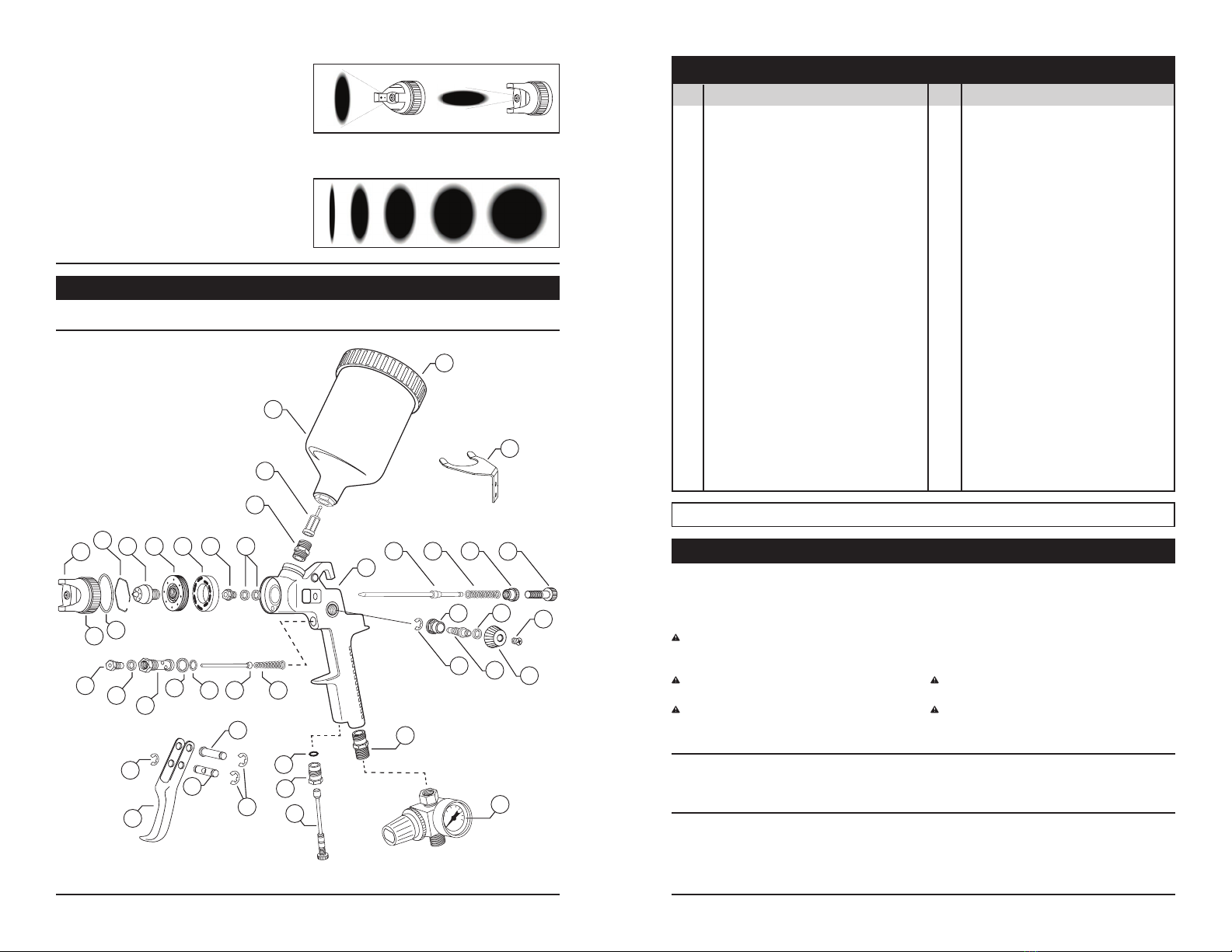
Step 2:
Air and Fluid Volume Controls - These
two controls are used in conjunction with
each other to accurately adjust air/uid
(Paint) ratio and will vary for different paints.
Changing one control uid volume affects
the other so alternating back and forth
between them to ne tune your adjustment
will yield optimum results.
Air Volume Control - Air volume is adjusted
by turning the air uid volume control knob.
Turning knob in reduces volume, turning knob
out control knob increases volume.
Inlet pressure is adjusted by turning the
pressure regulator Control Knob. Knob
must rst be pulled out to unlock. Turning
knob clockwise increases pressure, turning
knob counter-clockwise decreases pressure.
Once desired pressure is reached, push the
Air pressure:.....................15 - 45 P.S.I.
Spray pattern:...........................6 - 8 in.
Spray head & needle:................1.3 mm
Cup capacity:...............................700cc
1. Keep work area clean. Cluttered areas invite
injuries.
2. Observe work area conditions. Do not use
machines or power tools in damp or wet
locations. Don’t expose to rain. Keep work
area well lighted. Do not use electrically
powered tools in the presence of ammable
gases or liquids.
Always keep work area free from
obstructions and well ventilated.
3. Keep children away. Children must never be
allowed in the work area. Do not let them
handle machines, tools, hoses or extension
cords.
4. Store idle equipment. When not in use, tools
must be stored in a dry location to inhibit
rust. Always lock up tools and keep out of
reach of children and other untrained persons.
Switch off all unused electrical tools when
stored. Tools are dangerous in the hands of
untrained users.
5. WARNING: All persons in the work area
must always wear approved eye and ear
protection and approved breathing
apparatus when this spray gun is in
operation.
6. Work Safe. Do not wear loose clothing or
jewelry that could become caught by moving
parts, causing injury. Operate tool a safe
distance from yourself and others in the
work area. Keep proper footing and balance
at all times. Do not reach over or across
running machines, hoses, etc.
7.
Stay alert. Watch what you are doing, use common
sense. Be sure all personnel are clear of the
direction of the spray gun. Do not operate any
tool when you are tired.
8. Do not operate any tool if under the inuence
of alcohol or drugs. Read warning labels on
prescriptions to determine if your judgment
or reexes are impaired while taking drugs.
If there is any doubt, do not operate any tool.
9. Never aim spray gun at anyone. Do not spray
Avg. Air consumption (CFM):...........7-9
Fluid Inlet (NPS):.........................3/8 in.
Air Inlet (NPS):.............................1/4 in.
Hose size (ID):.............................3/8 in.
near sparks, open flame, lit cigarettes, pilot
lights, space heaters or any other potential
ignition source.
DO NOT SMOKE IN WORK AREA.
10. Follow air source manufacturers direc
tions for connection of regulators, lters,
and other accessories to air source. Do not
install quick couplers directly on tool as
they put unnecessary strain on the air inlet
threads possibly causing them to wear out
prematurely. Instead, install them on a short
length of air hose attached to the tool.
11. Follow manufacturers instructions and
safety information to ensure safe handling
and proper use of paints, lacquers, thinners,
base coats, etc. Do not use latex or other
heavy paints. They are not recommended
for this spray gun.
12. Always disconnect spray gun from air
source before disassembly.
13.WARNING: Solvents 1,1,1-Trichloroethane
and Methylene Chloride (Dichlorometh-
ane - sometimes called Methylchloride)
can chemically react with the Aluminum
used in most spray equipment creating an
explosion hazard. Read the label or data
sheet from the material you intend to spray.
NEVER use any material containing these
solvents. If unsure as to the composition of
your material, check with your supplier. Do
not use acids for cleaning.
14. Check for damaged parts. Before using
any tool, any part that appears damaged
should be carefully checked to determine
that it will operate properly and perform
its intended function. Check for alignment
and binding of moving parts; any broken
parts or mounting xtures; and any other
condition that may affect proper opera-
tion. Any part that is damaged should be
properly repaired or replaced by a qualied
technician.
15. Maintenance. For your safety, maintenance
should be performed regularly by a qualied
Step 1: Inlet Air Pressure Regulation
Assemble components of spray gun and
connect to clean air source as described
above. Clean air source is imperative to
ensure peak performance. The use of an
in-line air lter is highly recommended to
keep any contaminants from entering the
spray gun. Set inlet air pressure to between
40 and 45 P.S.I. to begin adjustments.
(This is a good operating inlet pressure suitable
for most applications, however, depending on
materials being sprayed and other external
factors such as temperature, humidity, etc.,
You may need to come back to this step and increase
or decrease pressure as needed after attempting
adjustments in step 2.)
Warning! Clean gun before and after
each use.
To protect the precision machined internal
parts and ttings in this gun from corrosion
during shipping, some oils or other corrosion
resistant agents may have been applied.
It is important to remove any such residue
before attempting to use the gun. To clean,
place a small amount of appropriate thinner
into paint cup and spray through gun while
pulling and releasing trigger repeatedly.
Wipe exterior of gun, nozzles and paint cup.
In some cases, if the gun becomes clogged,
disassemble completely and soak all parts
in thinner.
After soaking, use wire and cleaning brush to
clear small internal passages.
Check and clean paint cup lter. Replace if
worn. A clean air source is imperative to ensure
peak performance. The use of an in-line air
lter is highly recommended to keep any
contaminants from entering the spray gun.
Inspect all ttings and hardware to ensure
proper seating. Be sure air line ttings are
tight with no leaks. Replace any worn parts
as necessary. Check needle and nozzles for
nicks, scratches or burrs. Any such conditions
will seriously impair performance. Replace as
necessary.
CARE AND MAINTENANCE
OPERATION
technician using original PERFORMANCE
TOOLS® replacement parts. Failure to do
so can lead to accidents for the operator.
Use of any other parts will void the warranty.
Only use accessories intended for use with
this tool. Approved accessories are avail-
able from Performance Tool®. Use only
accessories that are recommended by the
manufacturer for your model. Accessories
that may be suitable for one tool may become
hazardous when used on another tool.
Instructions discussed in this instruction
manual cannot cover all possible conditions
and situations that may occur. It must be
understood by the operator that common
sense and caution are factors which cannot
be built into this product, but must be sup-
plied by the operator. Read and understand
all of the instructions provided in the instruc-
tion manual of this product, as well as, any
other tool (s) used with this product.
Continued on Pg.3
WARNING. READ, UNDERSTAND AND FOLLOW ALL INSTRUCTIONS AND WARNINGS
BEFORE OPERATING THIS PRODUCT. FAILURE TO DO SO MAY
RESULT IN FIRE, ELECTRICAL
SHOCK, PERSONAL INJURY AND/OR PROPERTY DAMAGE AND WILL VOID WARRANTY.
Fluid Volume
Control Knob
Fluid Volume
Lock Nut
Air Volume
Control Knob
Air
Nozzle
Spray Pattern
Control Knob
Regulated
Air-out to
Spray Gun
Unregulated
Air-Inlet
Pressure Regulator
Control Knob Locked
Pressure Regulator
Control Knob Unlocked

No. Description Qty.
1. Gun Body.................................1
2. Nozzle Cap...............................1
3. Washer .....................................1
4. Air Nozzle ................................. 1
5. Snap Ring ................................ 1
6. Fluid Nozzle..............................1
7. Brass Ring................................ 1
8. Nylon Gasket ...........................1
9. Packing Bushing ...................... 1
10. Washer .....................................2
11. Needle......................................1
12. Spring....................................... 1
13. Lock Nut...................................1
14. Fluid Volume Control Knob ...... 1
15. Paint Cup Bushing ...................1
16. Trigger ......................................1
17. Trigger Pivot Pin....................... 1
18. Needle Actuator Pin .................1
19. E-Clip .......................................4
20. Spray Regulator Nut ................1
No. Description Qty.
21. Spray Regulator Screw ............1
22. Teon Seal................................1
23. Spray Pattern Control Knob.....1
24. Screw .......................................1
25. Needle Valve Bushing .............. 1
26. Teon Ring ...............................1
27. Air Valve ...................................1
28. O-Ring......................................1
29. Washer .....................................1
30. Needle Valve ............................1
31. Spring....................................... 1
32. Air Inlet Bushing.......................1
33. Washer .....................................1
34. Air Volume Control Stem..........1
35. Air Valve Stem Bushing............1
36. Paint Cup Filter ........................1
37. Paint Cup Assembly.................1
38. Lid ............................................1
39. Air Regulator/Gauge Assembly 1
40. Wall Hanger..............................1
3 4
PARTS LIST
REPLACEMENT PARTS AVAILABLE:
WARNING - DISCONNECT SPRAY GUN FROM AIR SOURCE BEFORE MAKING ADJUSTMENTS
This device complies with Part 15 of the FCC Rules. Operation is subject to the following two
conditions: (1) this device may not cause harmful interference, and (2) this device must accept any
interference received, including interference that may cause undesired operation.
This instruction manual is intended for your benefit. Please read and follow the safety, installation,
maintenance and troubleshooting steps described within to ensure your safety and satisfaction. The
contents of this instruction manual are based upon the latest product information available at the time of
publication. The manufacturer reserves the right to make product changes at any time without notice.
SAFETY GUIDELINES / DEFINITIONS
WARNING: Read and understand this entire instruction manual before attempting to assemble, install, operate or maintain
this product. Failure to comply with the instructions may result in serious personal injury and/or property damage!
The following signal words are used to emphasize safety warnings that must be followed when using this product:
DANGER:
Indicates an imminently hazardous situation
that, if not avoided, WILL result in death or serious injury.
WARNING:
Indicates a potentially hazardous situation
that, if not avoided, COULD result in death or serious injury.
CAUTION:
Indicates a potentially hazardous situation
that, if not avoided, MAY result in minor or moderate injury.
NOTICE Indicates important information, which if not
followed, MAY cause damage to equipment.
Performance Tool repair kit: .......................................................... M710K
Step 3: Spray Pattern Controls Pattern
Shape - The shape of the spray can be
adjusted from a round pattern to a at
pattern by turning the pattern control knob.
Turning knob in, rounds the pattern. Turning
knob out, attens the pattern.
Pattern Orientation - A at or semi-round
spray pattern can be adjusted to any angle
from horizontal to vertical by turning the Air
Nozzle. Pattern is perpendicular to “ears”
on nozzle. That is, when the ears are horizontal
the spray pattern will be vertical and when
the ears are vertical the spray pattern will be
horizontal.
19
37
36
15
38
40
11 12 13 14
24
23
22
21
20
19
32
39
35
34
33
17
18
16
19
25 26
27
3
30 31
28 29
1
4
2
6
578910
Other PT Paint Sprayer manuals
Popular Paint Sprayer manuals by other brands

Berner
Berner BPT-PSG RP Instruction manual/safety instruction

Kobalt
Kobalt SGY-AIR84TZ user manual

Carlisle Fluid Technologies
Carlisle Fluid Technologies Binks Trophy 1465 Series manual

Schneider Airsystems
Schneider Airsystems FSP-FP-HTE2-1,3 Original operating manual

Brulin
Brulin BruTab 6S Use Directions

The Fountainhead Group
The Fountainhead Group Backpack Sprayer use and care manual