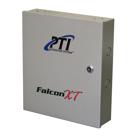
PTI security systems Falcon XT User manual

System Installation Manual
www.ptisecurity.com 800.523.9504
Revised March 2016

Thank you for purchasing the Falcon XT and StorLogix Access Control System. For
your complete satisfaction with this product, we recommend that you take the time to
thoroughly review this manual. It is designed to be followed from start to nish for the
installation of the Falcon XT Access Control System. If you have any difculties, we
strongly recommend that you review this manual prior to contacting Technical Support.
We also offer comprehensive training to help you become fully accustomed to the product.
Training can be customized to your site’s specic needs in classrooms at PTI Security
Systems Headquarters or on-site at your facility. Contact PTI Security Systems at (800)
523-9504 to arrange training for your site. Throughout the manual, there are cautions,
things to remember, hints, and suggested applications. Watch for these as they will help
make installation much smoother.
NOTE: This equipment has been tested and found to comply with the limits for a Class B digital device, pursuant to Part 15 of the
FCC Rules. These limits are designed to provide reasonable protection against harmful interference in a residential installation. This
equipment generates, uses, and can radiate radio frequency energy and, if not installed and used in accordance with the instructions,
may cause harmful interference to radio communications. However, there is no guarantee that interference will not occur in a particular
installation. If this equipment does cause harmful interference to radio or television reception, which can be determined by turning the
equipment off and on, the user is encouraged to try to correct the interference by one or more of the following measures:
• Reorient or relocate the receiving antenna.
• Increase the separation between the equipment and receiver.
• Connect the equipment into an outlet on a circuit different from that to which the receiver is connected.
• Consult the dealer or an experienced radio TV technician for help.
This Class B digital apparatus complies with Canadian ICES-003.
Cet appareil numérique de la classe B est conforme à la norme NMB-003 du Canada.
© 2012-2016 PTI Security Systems
All rights reserved.
No part of this publication may be reproduced, transmitted, transcribed, or translated
into any language in any form, by any means, without written permission of PTI Security
Systems.
Falcon XT™, StorLogix™, “Security Without Limits”™, “Security, Access : Control”™, LogixServer™,
LogixScript™, VideoViewer™, EventViewer™, Site Graphics™, “Easy to Implement, Simple to Use”™, are
trademarks of PTI Security Systems. All rights reserved.
Microsoft®Windows®, Adobe Reader®, Pentium®, McAfee Virus Scan®, Norton Antivirus®and all other
trademarks referenced are the property of their respective owners.
114A3866

CONTENTS
Chapter 1: Pre-Installation................................................................................................1
Overview ....................................................................................................................2
Specications.............................................................................................................3
Training ......................................................................................................................4
Pre-Installation Recommendations ............................................................................5
Equipment Location and Site Layout .........................................................................8
Falcon XT Location................................................................................................8
StorLogix Computer...............................................................................................8
Keypads and Proximity Readers ...........................................................................9
Door Alarm Multiplexers - Hardwired .....................................................................9
Door Alarm Multiplexers - Wireless........................................................................9
Door Alarm Switches .............................................................................................9
Power Supplies....................................................................................................10
Relay Boards .......................................................................................................10
Other Equipment..................................................................................................10
Tools Needed ...........................................................................................................12
Hardware Needed....................................................................................................13
Mounting Hardware Recommendations...................................................................13
Wire and Cable Needed...........................................................................................14
International Wire Cross-Reference.........................................................................16
Typical Wiring Scheme.............................................................................................17
Wire Splicing ............................................................................................................20
Surge Protection ......................................................................................................22
Chapter 2: Installation.....................................................................................................25
Unpacking the Falcon XT.........................................................................................26
Installing the Falcon XT ...........................................................................................27
Controller to Computer Connection .....................................................................28
For USB connections:..........................................................................................28
For RS232 connections: ......................................................................................28
For Ethernet connections:....................................................................................29
Controller to AI Devices Connection ........................................................................30
Output Relay Connections .......................................................................................32
Door Input Connections ...........................................................................................34
Wiegand Input Connections.....................................................................................35
Power Connections (North America)........................................................................36
Power Connections (International)...........................................................................38
Power Considerations..............................................................................................40
Adding Additional Power Supplies ...........................................................................42

iv
Chapter 3: Troubleshooting ............................................................................................41
Troubleshooting Concepts .......................................................................................42
Troubleshooting Gates.............................................................................................44
Appendix.........................................................................................................................45
System Requirements..............................................................................................46
Notices, Disclaimers, and Warnings ........................................................................49
Standard 2-year Equipment Warranty......................................................................51
Equipment Location .................................................................................................53
Site Closeout Checklist ............................................................................................54
Technical Support.....................................................................................................58
Technical Support/RMA Request .............................................................................59
Returning Equipment ..............................................................................................60
Site Service History..................................................................................................62
Dealer/Servicer Contact Information........................................................................66

ChapTEr 1: prE-INSTallaTION
Overview
Specications
Training
Pre-Installation Recommendations
Equipment Location and Site Layout
Tools Needed
Hardware Needed
Wire and Cable Needed
International Wire Cross-Reference
Typical Wiring Scheme
Wire Splicing
Surge Protection

2
Overview
The Falcon XT offers the access control industry the most
comprehensive hardware and software package. It is revolutionizing
the industry by integrating surveillance, access control, intrusion,
lighting, custom scripting, and elevator controls all in one package.
The Falcon XT provides the following features:
• 8 inputs on the main board that can be used for door alarms,
motion sensors, beams, or almost any other type of alarm switch
• 4 output relays on the main board that can be used to open
gates or doors, activate lights, control elevators, shunt alarms,
act as secure interior relays, or perform custom function
switching
• 2 Wiegand Protocol Device inputs on the main board that allow
the connection of proximity card devices, key fob devices,
biometric ngerprint devices, and many other types of Wiegand
protocol devices
• A built-in 12VDC 2A power supply with 4Ah battery backup
• Integration with a computer using RS232, USB, or Ethernet
TCP/IP
• Supports up to 127 Access Interface (AI) devices.
• Multiple Falcon XTs can be networked using LAN and WAN
congurations
• Can be connected to 900 MHz Wireless Access Devices
• Redundant Memory Backup

ChapTEr 1: prE-INSTallaTION
3
Specications
Power Supply:
Input Voltage: 24 VAC – 40 VA or 24 VDC – 2.5 A
Current Consumption: 250 mA Maximum
Output Voltage: 14 VDC – 2 A
Relay Outputs (resistive load):
Maximum Switching Voltage: 30 VAC/DC
Maximum Switching Current: AC: 10 A (NO) / 3 A (NC)
DC: 5 A (NO) / 3 A (NC)
Maximum Switching Capacity: 1250 VA 150 W (NO)
375 VA 90 W (NC)
Minimum Permissible Load: 10 mA at 5 VDC
Contact Resistance: 100 mΩ Maximum
Life Expectancy: (at maximum rated load)
Mechanical: 10,000,000 operations
Electrical: 200,000 operations minimum
Inputs:
Dry Contact Type ONLY. Do Not apply voltage to any of the inputs.
Dry Contact Specications:
Contact Resistance: 500 mΩ Maximum
Current Capacity: 100 mA at 5 VDC Minimum
Environmental:
Ambient Temperature: -40°C to +80°C (-40°F to 176°F)
Ambient Humidity: 0% to 100% (see note)
Note: The humidity inside the housing for any controller or AI Device cannot
exceed 85% and must be noncondensing.
See the Appendix for System Requirements for computers,
components, and peripherals used with the controller.

4
Pre-Installation Recommendations
Proper installation is the most important key to having a system
that functions and operates as it should. While it may seem to save
money in the short run by cutting corners on the installation, your
overall satisfaction with the system will be better if you spend the
time and money to do it correctly from the start. A poor installation
ultimately will be very frustrating, costing much more money as it can
lead to loss of revenue as well as many hours of technical support
and service personnel time to x issues with the install.
Choice of Installer
We strongly recommend that installation and setup of any PTI Security
Systems equipment be done by a certied, licensed, qualied,
and competent technician. We can recommend local dealers and
installers, but it is up to the customer to verify their qualications and
negotiate any pricing or contracts unless PTI Security Systems has
been specically contracted in writing to do so for the customer. With
any setup or installation, some troubleshooting and adjustment of the
conguration may be required. This will differ with every installation
and computer setup depending on many site-specic variables.
This troubleshooting and conguration may include purchasing
additional equipment. In no circumstances will PTI Security Systems
be responsible for any damages either incidental or consequential
based on these recommendations.
Code and Legal Considerations
Installation of equipment manufactured by PTI Security Systems must
be performed per our recommendations and guidelines except where
local, municipal, state, and provincial codes; the National Electrical
Code; and Construction codes take precedence. When code and
our guidelines do not cover a given situation, it is the installer’s
responsibility to contact PTI Security Systems for instruction and/
or follow established custom and best practices applicable to the
particular trade. Installers must know and abide by all existing laws
pertaining to their work. Meeting code is always your responsibility
and PTI Security Systems cannot be held liable if you do not
install to code.
Spend the time to nd
a reputable installer for
your site. Don’t just consider the
lowest price. Price is important,
but denitely not as important as
quality. A cheap, poor install will
always cost you more money than
a quality installation that costs a
little more initially.
We recommend that you take the
time to get several quotes from
different installers.
Check references and contact
the Better Business Bureau and
any local licensing bureaus. Look
for an installer that has been in
business in your area for years
and has a history of installing this
type of equipment.
Look for an installer who will
provide at least a 1 year warranty
on the installation and who
is willing to do a paid service
contract after that.

ChapTEr 1: prE-INSTallaTION
5
Never power auxiliary
devices such as
power door strikes, sirens, gate
operators, cameras, or any
other equipment from the same
power supply as AI devices are
connected to.
Never power auxiliary devices
such as power door strikes,
sirens, gate operators, cameras,
or any other equipment from the
controller. Only AI devices should
be powered from the controller.
These auxiliary devices should
be powered as per manufacturer
instructions with considerations
for amperage/current draw and
voltage requirements.
Powering auxiliary devices on
the same circuit as AI devices
or from the controller can cause
voltage drop in the system leading
to device lockup and intermittent
problems.
Power
Reliable equipment operation depends on a noise-free uninterrupted
source of power. The battery back-up feature is provided primarily
to preserve the integrity of the memory database and operation of
the controller. It does not guarantee operation of the gate motor or
door actuator for emergency situations in the event of a power loss
or equipment failure. It is the sole responsibility of the purchaser to
provide for and facilitate manual nonelectrical emergency means of
exit in the event of a power failure. Contact your local dealer/installer
for options and availability. Verify that there are enough 120V outlets
in the ofce (and/or maintenance rooms) where the equipment will be
located to support the equipment needs. Also, consider other ofce
equipment and electronics that require power such as copiers, fax
machines, computers, telephones, lights, water coolers, etc. Each
power supply, controller, computer, video monitor, etc. requires at
least one outlet. We recommend a minimum of two, 4-outlet stations
for the equipment; however your site may require more.
Auxiliary Security Devices
Power for door strikes, gate operators, sirens, cameras, and any
equipment other than the controller and AI devices must be provided
by separate power supplies. Never power a door strike or siren from
the same power supply to which an AI device is connected. This
must be considered when planning power needs for a site.
Wire
Refer to Wire Recommendations for recommendations on the proper
wire to be used with the controller. Be sure to plan on enough wire
plus an additional 10% – 15% for safety. Take into consideration the
linear distance, distance in rise for multiple oors, or the distance in
depth for burial when ordering wire. Be sure to pull an extra 10 feet of
wire at each end of a wire pull during installation. This allows enough
wire to meet the needs of the site without having to splice extra
wire. When installing AI devices, trim the excess, leaving a one-foot
service loop. Also, pull an extra 18 AWG 4-conductor wire throughout
the site and set aside several extra sets of 24 AWG 50-conductor
wires for future add-ons, maintenance, or repair of wiring. It is less
expensive and easier to do this up-front than to try and pull wire later.
Especially if additional construction is planned. PTI Security Systems
can supply the necessary wire for your needs. We recommend that
you use this wire as we have tested it over the years and know that,
if installed correctly, it works with our system.

6
Conduit
Consider purchasing the next size larger conduit than you need
to allow for future expansion and maintenance. Consider also
pulling extra wire-pull strings. This is especially important if future
construction phases or expansion are planned. Be sure to have pull
boxes at all conduit terminations. Use only electrical conduit with
sweep 90 degree bends. Never use sprinkler PVC, plumbing pipe, or
direct 90 degree elbow bends. All splices should be in junction boxes
above ground.
Advance Review
Review the manuals and documentation before installation. These
are available on our web site at www.ptisecurity.com and can also
be obtained by e-mail, fax, or U.S. mail by contacting Technical
Support. Order equipment with enough advance notice to have it
on-site prior to installation. When a shipment is received, promptly
check the equipment received against the packing list to verify
that all parts have been delivered. Also, verify that there isn’t any
shipping damage. If there is any shipping damage, retain all packing
materials and contact PTI Security Systems immediately (within 5
days of receipt). It is a good idea to plug everything in and verify that
you understand the set up prior to the full site installation. Contact
PTI Security Systems immediately if there are any issues.
It is a good idea to
order 10% - 15%
more multiplexer door channels
than you need and save a few
conductors in the door alarm
trunk line. Many sites layout their
units one way initially and later
come back and split larger units
into smaller ones to increase
prot on the square footage. This
increases the number of doors
and it can be very costly to go
back to pull new wire and install
new muxes in areas with already
rented units. The negligible cost of
preplanning saves a lot of money
in the long run.

ChapTEr 1: prE-INSTallaTION
7
Keep a map of the site
showing the location of
every AI device, power supply,
system component, wire direction,
and junction box. The installer
should keep a copy of this in their
customer records for the site and
the site should also maintain a
copy along with the manuals in
a location that is safe but easily
accessible for those who might
need to maintain, service, or
troubleshoot the equipment.
Equipment Location and Site Layout
Equipment and mounting locations should be laid out and planned
in advance of installation. Use a set of site plans to lay equipment
locations and to determine the amount of conduit and wire needed.
A copy of this can be sent to your PTI Security Systems Sales
Representative so they can review it with you to make sure that
you get the equipment that you need. Be sure to discuss the local
code particular to your municipality with your Sales Representative.
Plans should be kept in a safe location after the site is complete to
help with future additions and site maintenance.
Falcon XT Location
A secure room, closet, or cabinet should be set aside for the Falcon
XT. This room often will also contain DVRs, power supplies, relay
boards, wireless multiplexers, and alarm panels. This room should
have adequate ventilation with air conditioning and be secure, but
with access for maintenance.
StorLogix Computer
The StorLogix computer is generally located at the main desk but
must have some proximity to the controller depending on cable
length and type of connection. Refer to Connecting the Controller to
the Computer for more information.
Keypads and Proximity Readers
Keypads and proximity readers are generally mounted on gooseneck
stands or bollards, or on the wall near the gate, door, or elevator that
is being accessed. Be sure to consider trafc ow, ease of access,
Americans with Disabilities Act Standards (ADA), and local code
when planning the mounting location. Gooseneck stands, bollards,
and gate operators are generally mounted on a concrete pad. Refer
to manufacturer instructions for pad size and type.
The relay that trips a gate or door should be located in a secure
area and is called a secure interior relay. For example, a gate has
an entrance keypad and an exit keypad. The gate operator should
only be connected to the exit keypad relay. When a client uses the
entrance keypad, the Falcon XT is programmed to use the exit
keypad’s relay to open the gate. This prevents anyone from breaking
into the keypad or bollard and crossing wires to open the gate.
Never install an AI
device inside a unit
that will be rented or in any
other area that is not easily
accessible for future maintenance,
expansion, or troubleshooting.

8
Door Alarm Multiplexers - Hardwired
Door alarm multiplexers are generally mounted high on the side of a
building or high on a wall in a hallway that allows access by ladder
for maintenance if needed, but is out of reach of the general public.
Multiplexers should never be mounted inside of a unit that will be rented
or otherwise inaccessible. Multiplexer boxes are weather-resistant and
can be mounted in exterior locations, but not under a downspout.
Door Alarm Multiplexers - Wireless
Wireless door alarm multiplexers are generally mounted in the
ofce or security cabinet with the receiver mounted high on a wall.
Repeaters are generally located as needed throughout the property,
but must have access to 120VAC power.
Door Alarm Switches
Most hardwired door alarm switches and magnets are placed on
the inside latch side of the door. Wireless door alarm transmitters
are usually placed on the other side of the door. Switch and magnet
installation must never interfere with door movement.
Power Supplies
Power for AI devices is provided by the controller. Additional power
supplies for the AI devices may be placed throughout the site as
necessary for voltage drop and current draw considerations.
Additional power supplies must always be wired with an RB5 relay to
allow central reset capability. See Adding Additional Power Supplies
for more information. Power for other equipment such as cameras,
sirens, door strikes, and gates must be considered per manufacturer
recommendations.
Relay Boards
Relay boards are generally installed in interior locations or inside
junction boxes that are accessible for maintenance if needed. Relay
boards should never be mounted inside a unit that will be rented
or otherwise inaccessible. Relay boards for elevator controls will
generally be in or very near the elevator control room.
Other Equipment
DVRs, alarm panels, sirens, cameras, and most other equipment will
be located as to manufacturer recommendations.

ChapTEr 1: prE-INSTallaTION
9
Tools Needed
The following tools are necessary to complete a normal installation.
Depending on the construction of the site and other considerations,
other tools may be required.
A. Rotary Hammer Drill
B. Caulking Gun
C. Drywall Punch Saw
D. Assorted Screwdrivers
E. Precision Screwdrivers
F. ¼” Nut Driver
G. Multimeter
H. Wire Fish Tape
I. Bits for Hammer Drill
J. Bits for Drill/Driver
K. Drill Screw Bit
L. 3M E9-Y Crimper
M. Crimping Pliers
N. Wire Strippers
O. Wire Cutters
P. Assorted Pliers
Q. Flashlight
R. Sharp Markers
S. Tape Measure
T. Hole Saw
U. Rechargeable Drill/Driver
V. Claw Hammer
W. Razor Blade or Knife
X. Assorted Tin Snips
Y. Wireless Tester*
Z. Mux Punchdown Tool*
AA. Assorted Hex Keys*
BB. Rivet Gun
CC. Scissors or Shears
DD. Torpedo Level
EE. Assorted Box Wrenches
FF. Assorted Vice Grips
GG. Adjustable Wrenches
HH. Safety Glasses
II. Work Gloves
JJ. Conduit Bender
KK. 9V Battery w/ Test Clips
LL. Conduit Cutter/Reamer
MM. Hack Saw
* Note: Items shown with an asterisk are sold by PTI Security Systems.

10
Hardware Needed
The following hardware is necessary to complete a normal installation.
Depending on the construction of the site and other considerations,
other hardware may be required.
A. Red Head Concrete Wedge Anchors
B. Tapcon Concrete Anchors +
C. Hammer Set Concrete Anchors
D. Self Tapping Screws +
E. Sheet Metal and Wood Screws +
F. Drywall Screws +
G. Toggle Bolts +
H. Machine Washers +
I. Plastic Wall Anchors +
J. Heavy Duty Self Drilling Drywall Anchor+
K. Sheet Metal Rivets +
L. Screwhead Mounting Wire Ties +
M. Cable Clamps and Mounts +
N. Caddy Clips +
O. 18 AWG Spade Connectors
P. 3M U-Type Connectors (UR2, UY2, UG) *
Q. Wire Nuts +
R. Electrical Tape
S. PL Premium Construction Adhesive
T. Silicone Sealant – Heavy Duty Outdoor
U. Fire Barrier Sealant
V. Panduit Wire Raceway
W. Wire Pulling Lubricant
X. Conduit Compression Fittings/Mounts +
Y. Flexible Conduit
Z. Electrical Conduit with Sweep 90 Bends
+ Note: Assorted lengths, sizes, and types will be needed of these.
* Note: Items shown with an asterisk are sold by PTI Security Systems.
Mounting Hardware Recommendations
Surface Type for Mounting Recommended Mounting Hardware
Drywall between Studs Self Drilling Drywall Anchors or Toggle Bolts
Drywall on Studs Self Tapping Drywall Screws
Stucco Toggle Bolts
Wood Drywall Screws
Sheet Metal Self Tapping Sheet Metal Screws
Hollow Block Tapcon Concrete Anchors or Toggle Bolts
Brick or Solid Block Tapcon Concrete Anchors or Concrete Wedge Anchors
Masonry or Concrete Tapcon Concrete Anchors or Concrete Wedge Anchors
All anchors should be size #8 head with a length of 1½ inches or longer (based on wall depth)

ChapTEr 1: prE-INSTallaTION
11
Using the incorrect
wire for an application
can cause many problems with
voltage drop, RF interference,
and ground faults; resulting in lost
revenue and greatly increased
costs for service, reinstallation,
repair, and technical support
Always refer to local code prior to
ordering the wire for your site, as
these requirements may be more
stringent.
Wire and Cable Needed
The following are the recommended wire types for installing PTI
Security Systems manufactured products as well as many of the
other access control and security products that we sell to compliment
our system. Planning and installing the wiring of a site is a process
that requires a high degree of technical knowledge; we recommend
that this be done by a trained professional.
AI Device Power & Data Wire Recommendation
(from Controller to AI Devices)
PTI Part # Belden
Wire Code
Ω per 1000’
Resistance Description
wwir1804s * 9418 6.92
18 AWG, 4-conductor stranded copper
wire with overall shield and common
ground (PVC Insulation)
wwir1804spl 89418 6.92
18 AWG, 4-conductor stranded copper
wire with overall shield and common
ground (Plenum Insulation)
wwir1804sdb 9552 6.92
18 AWG, 4-conductor stranded copper
wire with overall shield and common
ground (Direct Burial)
* Denotes standard recommended wire.
Standard CAT5 cable can be used for RS-485 data communications with this system. Be
sure to correctly identify the twisted pair that will be used. A seperate 18AWG power line
will need to be run or dropped when using CAT5.
Never use wire smaller than 18 AWG for installing power to AI devices.
Never use any unshielded wire for installing power and data to AI devices.
Data wire length should never exceed 4000’ in a single linear distance.
Maximum length for power will vary signicantly because of voltage drop due to current
draw, number of devices, splices, and other factors.
Door Alarm Wire Recommendation (from Multiplexer to Door Switch)
PTI Part # Belden
Wire Code
Ω per 1000’
Resistance Description
wwir2450 * 9585 25.67 24 AWG, 50-conductor solid copper wire
(PVC Insulation)
wwir2450pl N/A 25.67 24 AWG, 50-conductor solid copper wire
(Plenum Insulation)
wwir2450db 165185110 25.67 24 AWG, 50-conductor solid copper wire
(Direct Burial)
* Denotes standard recommended wire.
Never use wire smaller than 24 AWG for installing door switches.
Never use stranded wire for installing door switches.
Applications that require shielded trunk line, use direct burial cable.
We strongly
recommend that you
purchase the wire for your system
from PTI Security Systems as we
have determined the most ideal
wire over years of experience and
testing.

12
Intercom Wire Recommendation (from LEF or NEM Base Station to intercoms)
PTI Part # Belden
Wire Code
Ω per 1000’
Resistance Description
wwir1810s * 5345FE 6.92
18 AWG, 10-conductor stranded copper
wire with overall shield and common
ground (PVC Insulation)
wwir1804s * 9418 6.92
18 AWG, 4-conductor stranded copper wire
with overall shield and common ground
(PVC Insulation)
wwir1802s 8760 6.92
18 AWG, 2-conductor stranded copper wire
with overall shield and common ground
(PVC Insulation)
wwir2210s 9946 17.5
22 AWG, 10-conductor stranded copper
wire with overall shield and common
ground (PVC Insulation)
* Denotes standard recommended wire.
Never use wire smaller than 22 AWG for installing LEF or NEM intercoms. We recommend
that 18 AWG be used in most installations for best results. Do not exceed 1600 feet in
linear distance when using 18 AWG or 600 feet in linear distance using 22 AWG.
Cameras/Video Wire Recommendations (From DVR to Camera)
PTI Part # Belden
Wire Code
Ω per 1000’
Resistance Description
wwirsiamese * 549945 10.15/6.92 RG59U / 18 AWG 2-conductor in same
cable (PVC Insulation)
wwirsiamesepl 649948 10.15/6.92 RG59U / 18 AWG 2-conductor in same
cable (Plenum Insulation)
wwirrg59u 8241 10.15
Coaxial Cable with 22 AWG core and
stranded copper common ground (PVC
Insulation)
wwirrg59upl 89259 10.15
Coaxial Cable with 22 AWG core and
stranded copper common ground (Plenum
Insulation)
wwirrg59udb 8212 10.15
Coaxial Cable with 22 AWG core and
stranded copper common ground (Direct
Burial)
wwir1802s ** 8760 6.92
18 AWG, 2-conductor stranded copper
wire with overall shield and common
ground (PVC Insulation)
wwir2210s *** 9946 17.5
22 AWG, 10-conductor stranded copper
wire with overall shield and common
ground (PVC Insulation)
wwir2450 *** 9585 25.67 24 AWG, 50-conductor solid copper wire
(PVC Insulation)
* Denotes standard recommended wire
** 1802S can be used for power by many types of cameras.
*** 2450 or 2210 can be used for interior video signal using Baluns (see Application Note).
Baluns are video signal
converters that allow
twisted pair cable to be used to
carry video signals up to 1200
feet. Two baluns are required
for each camera connection
(one at the camera end and
one at the DVR end). This is an
efcient way to run video signal
on sites with a lot of cameras.
Contact a PTI Security Systems
Sales Representative for more
information on Baluns.
When retrotting an
existing facility, we do
NOT recommend that you use the
existing wiring. New wire should
be pulled and all new connections
made. Old wiring is often the
source of many problems in a
system and the initial investment
to install new wire will make the
overall retrot experience much
better as there is less likely to be
problems in the new wiring if it is
installed correctly.

ChapTEr 1: prE-INSTallaTION
13
International Wire Cross-Reference
The chart below shows the nearest approximate wire equivalents for
several international wire gauge standards for use with PTI Security
Systems products. It is usually better to use a slightly thicker wire
than a thinner one (especially over longer distances). Always refer to
local electrical codes and regulations as these requirements may be
more stringent. Refer to the wire type requirements on the previous
pages for cross reference.
AWG
American Wire Gauge
SWG/Imperial
British Standard Gauge
Metric
Metric Wire Gauge
CSA
Cross-Sectional Area
16 18 or 17 14 2.50 mm2
18 19 or 18 12 2.00 mm2
20 21 9 or 8 1.50 mm2
22 22 7 1.25 mm2
24 24 6 1.00 mm2
Typical Wiring Scheme
The following pages show a typical site wiring scheme. These are
shown in order to give the installer an idea of equipment layout and wire
planning. Each site will be different and must be planned accordingly.
USB, RS232, or
Ethernet line
Workstation 1 with
StorLogix Client
Server with StorLogix
Server (Includes
LogixServer)
TCP/IP LAN
Falcon XT
Controller
Entry
Keypad
•EnterAccess Code
•Press the # Key
-Press
IntercomCall
Welcome
•Press the Key
*
l
e
t
n
I
m
o
c
r
l
a
C
*
7
4
8
0
5
12
9
#
6
3
Exit
Keypad
•EnterAccess Code
•Press the # Key
-Press
IntercomCall
Welcome
•Press the Key
*
l
e
t
n
I
m
o
c
r
l
a
C
*
7
4
8
0
5
12
9
#
6
3
Multiplexer
To Other Access
Interface Device(s)
Workstation 2 with
StorLogix Client
Workstation 3 with
StorLogix Client
To Other
Workstation(s) with
StorLogix Client
Cameras
DVR
RS485 Line
Graphics
Computer

14
TO OTHER
AI DEVICES
REFER TO GATE OPERATOR MANUFACTURER
INSTALLATION INSTRUCTIONS FOR PROPER
WIRING TO KEYPAD RELAY.
ENTRANCE KEYPAD
GATE OPERATOR
EXIT KEYPAD
CONNECT TO
EARTH GROUND
CONNECT TO
EARTH GROUND
(DC POWER
CONNECTION
SHOWN)
(DC POWER
CONNECTION
SHOWN)
CONTROLLER
REFER TO SIREN MANUFACTURER
INSTALLATION INSTRUCTIONS
FOR PROPER SIREN WIRING.
12VDC
POWER
SUPPLY
DEDICATED POWER
SUPPLY FOR SINGLE
SIREN ONLY
EARTH GND
BATTERY
TO
SOFTWARE
COMPUTER
-OR- -OR-
CIRCUIT BOARD

ChapTEr 1: prE-INSTallaTION
15
REFER TO DOOR STRIKE MANUFACTURER
INSTALLATION INSTRUCTIONS FOR
PROPER WIRING TO KEYPAD RELAY.
FROM OTHER
AI DEVICES
12VDC DOOR
STRIKE
12VDC
POWER
SUPPLY
BUILDING ENTRANCE
KEYPAD
DEDICATED POWER
SUPPLY FOR SINGLE
DOOR STRIKE ONLY
CONNECT TO
EARTH GROUND
(DC POWER
CONNECTION
SHOWN)
TO OTHER AI DEVICES
(REFER TO THE 'INSTALLING
THE AI DEVICES' CHAPTER
FOR SPECS ON AI DEVICES)
RELAY BOARD
MUX

16
Wire Splicing
Wire splices must be kept to a minimum. Every splice increases the
conductive resistance, reducing the effective distance of the electrical
power or signal. Also, every splice is a potential failure point for the
system due to the danger of corrosion in the wire, improper joint
connections, radio frequency interference, ground faults, and other
factors. Improper splices run the risk of intermittent system problems
that can be very difcult to troubleshoot. Try to plan and install the
site so that the only splices in the system occur in the terminal blocks
that connect to each AI device. If a splice is absolutely necessary,
it must be done in an above-ground, weatherproof, electrical-rated,
junction box. The proper procedure for making a wire splice is as
follows:
1. Inside the junction box, pull an extra foot of
wire for each side of the splice. This is called
a service loop and allows extra wire for future
service or replacement of the splice if it is
done incorrectly, becomes corroded, or is
otherwise damaged.
2. Trim back 1½ inches of the outside insulation
jacket on the cable. Do NOT strip the
insulation off the individual conductor wires
themselves. Place the two wires to be spliced
side by side and twist them together for about
½ inch, leaving about 1 inch of wire free to be
slid into a 3M U-Type connector. 3M U-Type
connectors can be purchased from PTI
Security Systems.
NOTE: Do not leave copper wire exposed. The outside sheathing is necessary
for the strength of the connection.
Never splice two
different colors, gauges,
or types of wire. It is extremely
important that wire color, gauge,
type, and purpose of each wire
remain consistent throughout a
site.
For example: If you are following
PTI Security Systems’ wiring
recommendations, the DC+ wire
should be red, 18 AWG stranded
copper wire throughout the site.
Never pull spliced
wire through conduit.
Splices should only be made in
wire that is already pulled into a
junction box.
Other manuals for Falcon XT
1
Table of contents
Other PTI security systems Security System manuals
Popular Security System manuals by other brands
X10
X10 PK9000 Set up and operating instructions
Data Aire
Data Aire MINI DATA ALARM PROCESSOR II Operation and maintenance manual

aquilar
aquilar AquiTron AT-RAP-230 Installation & operation instructions
FlowLine
FlowLine Strobe Alert LC09-1001 Series manual
Niko
Niko PSS 25 Assembly and operation instructions
Encore
Encore ENXDVR-4C user manual
