manuals.online logo
Brands
  1. Home
  2. •
  3. Brands
  4. •
  5. Pulsar
  6. •
  7. Switch
  8. •
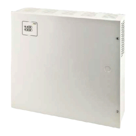
  9. Pulsar PSB1002435 User manual

Pulsar PSB1002435 User manual

1
PSB1002435
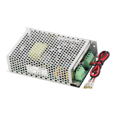
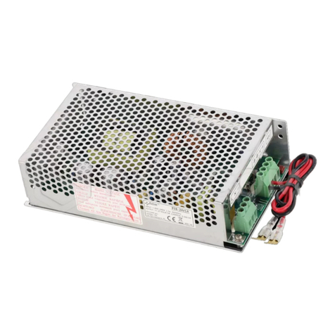
PSB 27,6V/3,5A enclosed switch
mode b
uffer power supply
Edition: 1 z from 10.11.2011
Supercedes edition: ……………….. EN
Features of the power supply:
•DC 27,6V/3,5A uninterruptible power supply
•wide AC input voltage range 176÷264V
•high efficiency 83%
•controlling of battery charging and maintaining
•protecting of battery against excessive
discharging (UVP)
•battery charging current 0,5A/1A,
changed by jumper
•battery output is full protected against short-
circuit and reverse connection
•LED optical signalisation
•protections:
•SCP short-circuit protection
•OVP overvoltage protection
•overvoltage protection (output AC)
•overload (OLP)
1. Technical description.
1.1.General description.
Buffer-type power supply units are intended for continuous power supply to devices that require stabilised voltage
of 24 V DC (+/-15%). The power supply provides a voltage of U=27,6 V DC with an output current of:
1. Output current of 3A + 0,5A battery charging.
2. Output current of 2,5A + 1A battery charging.
Total device current + battery: 3,5A max.
In case of power voltage decay, prompt switching to battery supply occurs. The power supply has the following
protections: short-circuit (SC ), overload (OL ) and overvoltage (OV ).
1.2.Technical parameters.
Supply voltage 176÷264V AC 50÷60Hz
Current consumption 0,90A@230VAC max.
Supply power 100W max.
Efficiency 83%
Output voltage 27,6V DC – buffer operation
19V÷27,6V DC – battery operation
Output current
3A + 0,5A
battery charging
2,5A + 1A battery charging
Output current t
AMB
<30°C 3A + 0,5A battery charging - refer to graph 1.
2,5 A + 1A battery charging - refer to graph 1.
Output current t
AMB
=40°C 2A + 0,5A battery charging - refer to graph 1.
1,5 A + 1A battery charging - refer to graph 1.
Voltage adjustment range 24÷28V DC
Ripple voltage 150mV p-p max.
Battery charging current 0,5A or 1A max
Short-circuit protection SCP electronic
Overload protection (battery) OLP polymer fuse (PTC)
Overvoltage protection OVP U>115% ÷ 150% of the output voltage, isolation of the
output voltage, atomatic recovery
Excessive discharge protection UVP U<19 V (± 5%) – disconnection of battery
Optical signalisation green LED- presence of AC voltage
Output of optical signalization LED AC- presence of AC voltage
LED DC- presence of DC voltage on power supply output
Operation conditions 2-nd enviromental class, temperature: -10
o
C÷40
o
C
relative humidity 20%...90%, without condensation

2
Dimensions (LxWxH) 199 x 97 x 42 [mm]
Net/gross weight 0,63kg / 0,68kg
Protection class PN-EN 60950-1:2007 I (first) - requires a protective conductor (PE)
Connectors power-supply: Φ0,63÷2,5 I/O PCB : Φ0,41÷1,63
battery output BAT: 6,3F-2,5/40cm,
output of optical signalization: plug 3-pin 5 mm
Electrical strength of insulation:
- between input (network) circuit and output circuits
of power-supply (I/P-O/P)
- between input circuit and PE protection circuit (I/P-
FG)
- between output circuit and PE protection circuit
(O/P-FG)
3000 V/AC min.
1500 V/AC min.
500 V/AC min.
Insulation resistance:
- between input circuit and output or protection
circuit
100 MΩ, 500V/DC
Storage temperature -20ºC...+60ºC
Vibrations and impulse waves during transport according to PN-83/T-42106
1.3. Output current vs temperature.
Graph 1.
Allowable output current from the power
supply depending on ambient temperature.
2. Installation.
2.1. Requirements.
The buffer power supply shall be mounted by the qualified installer having appropriate (required and necessary
for a given country) permissions and qualifications for connecting (operating) 230V/AC installations and low voltage
installations. The device shall be mounted in closed rooms, according to the environment class II, of the normal air
humidity (RH=90% max. without condensation) and the temperature within the range from -10°C to +40°C.
The power supply shall be mounted in a close casing (a cubicle, a terminal device) and in order to fulfill LVD and
EMC requirements the rules for power-supply, encasing and shielding shall be observed according to application.
Due to the power supply design, the PE wire has to be connected to the corresponding connector of the
supply unit. Operation without proper grounding of the power supply is not allowed!
Prepare the power supply loading balance before installation:
1. Output current of 3,0A + 0,5A battery charging.
2. Output current of 2,5A + 1,0A battery charging.
Total device current + battery: 3,5A. max.
2.2. Installation procedure.
1. Before beginning installation, ensure that the power in the 230V AC power supply circuit is disconnected.
2. Install the unit in the previously selected place.
3. Connect the 230VAC power leads. Connect the PE cable (yellow-green) to an appropriate terminal on the
power supply unit (marked with ).
The circuit of the shock protection shall be performed with a particular care, i.e. the yellow and green
protection wire of the power cable shall be connected from one side to the terminal marked by the
symbol of in the casing of the power-supply. Operation of the power-supply without the properly
made and fully operational circuit of the shock protection is
UNACCEPTABLE!
It can result in failure of devices and electric shock.
3
4. Connect load/loads to proper output connectors of the power supply (positive end is marked as +V,
negative as -V).
5. Connect battery to the unit according marks (colors).
6. After the completion of tests and trial activation, close the housing, cabinet etc.
2.3. Description of terminals.
Elements/connectors
[Fig.1] Description
L, N,
L
-
N
- input voltage connectors 230 V AC,
– protective conductor connector
-V Power supply output (0V)
+V Power supply output (+27,6V)
LED1 LED signals the presence of AC voltage
ADJ Potentiometer - output voltage adjust
I1/I2
Jumper -battery charging current configuration:
Ibat =0,5 A
Ibat =1,0 A
Legend: jumper installed, jumper removed
B+ Battery terminal- positive (+)
Fig 1. Description of terminals.
B- Battery terminal- negative (-)
Z1 Connector of optical signalization
2.4. Dimensions and fitting of the PSB1002435 power supply.
Fig. 2. Dimensions of power supply
3. Maintenance.
All maintenance procedures can be performed after the disconnection of the power supply from the electrical grid.
The power supply does not require any special maintenance procedures, but in the case of significant dust accumulation,
dusting using compressed air is recommended.
4
WEEE designation
The waste electric and electronic equipment worn out may not be disposed of together
with standard household waste. According to the WEEE directive, applicable in the EU,
the separate neutralization methods should be used for electric and electronic
equipment.
Pulsar K.Bogusz Sp.j.
Siedlec 150, 32-744 Łapczyca, Poland
Tel. (+48) 14-610-19-40, Fax. (+48) 14-610-19-50
e-mail:
[email protected]
,
[email protected]
http://
www.pulsar.pl
GENERAL WARRANTY CONDITIONS
1. Pulsar K. Bogusz Sp.j. (manufacturer) grants a two-year quality warranty for the equipment, starting from the date of purchase
placed on the purchase order.
2. Should such purchase order be missing when the claim is submitted, the three-year guarantee period is counted from the date
of the manufacturing of the device.
3. The warranty includes free-of-charge repairing or replacing with a functional equivalent (the selection is made by the
manufacturer) of the malfunctioning device, due to reasons attributable to the manufacturer, including manufacturing and material
defects, unless such defects have been reported beyond the warranty period (item 1 and 2).
4. The equipment subject to warranty is to be brought to the place where it was purchased, or directly to the main office of the
manufacturer.
5. The warranty applies to complete equipment, including the type of defect specified in writing, using a properly filled warranty
claim.
6. Should the claim be accepted, the manufacturer is obliged to render warranty repairs, as soon as possible, however not later
that within 14 days from the delivering of the equipment to the service centre of the manufacturer.
7. The repair period mentioned in item 6 may be prolonged, if there is no technical capability to carry out the repairs, and in the
case that the equipment has been accepted conditionally, due to the failing of the warranty terms by the claimant.
8. All the services rendered by force of the warranty are carried out at the service centre of the manufacturer, exclusively.
9. The warranty does not cover the defects of the equipment, resulting from:
- reasons beyond the manufacturer's control,
- mechanical damage,
- improper storage and transport,
- use that violates the operation manual or equipment application,
- random events, including lightning discharges, failures of power networks, fire, flooding, high temperatures and chemical agents,
- improper installation and configuration (at variance with the rules set forth in the manual),
10. Each confirmation of structural modifications or repairs, carried out beyond the service centre of the manufacturer, or any
modification of serial numbers or warranty labels, results in the loss of the rights resulting from the warranty.
11. The liability of the manufacturer towards the buyer is limited to the value of the equipment, determined according to the
wholesale prices suggested by the manufacturer on the day of purchase.
12. The manufacturer shall not be responsible for the defects that resulted from the damaging, malfunctioning or inability to
operate the equipment, particularly, if such defects are the result of failing to abide by the recommendations and requirements
contained in the manual, or the use of the equipment.

Other Pulsar Switch manuals

Pulsar SFG64 User manual

Pulsar

Pulsar SFG64 User manual

Pulsar S108-B User manual

Pulsar

Pulsar S108-B User manual

Pulsar SF124 User manual

Pulsar

Pulsar SF124 User manual

Pulsar S124WP User manual

Pulsar

Pulsar S124WP User manual

Pulsar ISF108 User manual

Pulsar

Pulsar ISF108 User manual

Pulsar S98 User manual

Pulsar

Pulsar S98 User manual

Pulsar S64-CRB User manual

Pulsar

Pulsar S64-CRB User manual

Pulsar S98-BR User manual

Pulsar

Pulsar S98-BR User manual

Pulsar S108-CRB User manual

Pulsar

Pulsar S108-CRB User manual

Pulsar S54-B17 User manual

Pulsar

Pulsar S54-B17 User manual

Pulsar RSUPS54 User manual

Pulsar

Pulsar RSUPS54 User manual

Pulsar S64-BR User manual

Pulsar

Pulsar S64-BR User manual

Pulsar PSB-12V15A User manual

Pulsar

Pulsar PSB-12V15A User manual

Pulsar PSB-251215 User manual

Pulsar

Pulsar PSB-251215 User manual

Pulsar SG108-C User manual

Pulsar

Pulsar SG108-C User manual

Pulsar SF116 User manual

Pulsar

Pulsar SF116 User manual

Pulsar S54-CRB User manual

Pulsar

Pulsar S54-CRB User manual

Pulsar SG108-BR User manual

Pulsar

Pulsar SG108-BR User manual

Pulsar SF116 User manual

Pulsar

Pulsar SF116 User manual

Pulsar SF108 User manual

Pulsar

Pulsar SF108 User manual

Pulsar ISFG64 User manual

Pulsar

Pulsar ISFG64 User manual

Pulsar S94-CR User manual

Pulsar

Pulsar S94-CR User manual

Pulsar S108-BR User manual

Pulsar

Pulsar S108-BR User manual

Pulsar SG64WP User manual

Pulsar

Pulsar SG64WP User manual

Popular Switch manuals by other brands

TP-Link TL-SX105 installation guide

TP-Link

TP-Link TL-SX105 installation guide

LEGRAND 0065403 quick start guide

LEGRAND

LEGRAND 0065403 quick start guide

schmersal AZ 415-33ZPDK operating instructions

schmersal

schmersal AZ 415-33ZPDK operating instructions

Juniper EX2200 Series Hardware guide

Juniper

Juniper EX2200 Series Hardware guide

UE ONE Series Installation & maintenance instructions

UE

UE ONE Series Installation & maintenance instructions

ZooZ ZEN71 800LR user manual

ZooZ

ZooZ ZEN71 800LR user manual

Zamel EXTA WZM-02 instruction manual

Zamel

Zamel EXTA WZM-02 instruction manual

Black Box ServSelect IP VM KV2116A Installer/user guide

Black Box

Black Box ServSelect IP VM KV2116A Installer/user guide

Fore Systems ES-2810 user guide

Fore Systems

Fore Systems ES-2810 user guide

NIVELCO MR Series user manual

NIVELCO

NIVELCO MR Series user manual

Lindy 32351 manual

Lindy

Lindy 32351 manual

Enabling Devices Cushion Grip Switch user guide

Enabling Devices

Enabling Devices Cushion Grip Switch user guide

Cypress CPRO-3D41GAME Operation manual

Cypress

Cypress CPRO-3D41GAME Operation manual

Enerwave ZW500DM-PLUS installation instructions

Enerwave

Enerwave ZW500DM-PLUS installation instructions

Cisco MDS 9000 Series Configuration guide

Cisco

Cisco MDS 9000 Series Configuration guide

Planet GSW-4804SF Quick installation guide

Planet

Planet GSW-4804SF Quick installation guide

Planet WGSW-28040 user manual

Planet

Planet WGSW-28040 user manual

Leviton decora smart DZ15S installation instructions

Leviton

Leviton decora smart DZ15S installation instructions

manuals.online logo
manuals.online logoBrands
  • About & Mission
  • Contact us
  • Privacy Policy
  • Terms and Conditions

Copyright 2025 Manuals.Online. All Rights Reserved.