Pyroterra Lighttoys FT2 User manual

Pyroterra Lighttoys
presents
FT2 CHIP
INSTALLATION GUIDE
v1.4
Note: installation of the FT2 chip must be performed
only by individuals with knowledge of electronic
circuits and soldering skills.

Introduction
FT2 chip brings the power of digital pixel LED strips into your custom
LED decorations, costumes and props. The FT2 chip offers full
compatibility with FT remotes, other Lighttoys props and the
LtComposer programming software. Thanks to its cutting-edge
features and flexible installation options, FT2 chip opens new
creative possibilities for the discerning artist.
Chip specification
dimensions: 58 x 16 x 6 mm, weight: 4.9 g
supported LED strips: 5V digital LED strips (APA102, WS2812,
WS2813 variants)
supply voltage: 3.3-5.0V, stabilized output voltage: 4.0V
max. output power: 40W / 10A (~180 LEDs at max. brightness)
number of LEDs: 10-300 (per each digital output)
operational temperature: -10°C to +90°C
USB-C fast charging: yes 1.5A
Modes of operation
The FT2 chip can be installed & operated in 2 different ways:
A) Battery powered using the voltage converter (recommended)
B) Bypassing the voltage converter (advanced)

A) Battery powered using the voltage
converter
This is the recommended use of the FT2 chip in most scenarios.
The FT2 chip includes a DC-DC boost voltage converter that manages
stable output voltage (~3.9V), even as the battery voltage drops
under high load and discharge, providing a stable and reliable
functionality of the attached LED strip(s).
Digital LED strip attachment
The FT2 chip is fully compatible with the 4-wire APA102 LED strip and
the 3-wire WS2812 LED strip (including all their variants). We
recommend the APA102 based on its superior performance.
The FT2 chip has 2 sets of digital outputs, one from each side of the
board. The digital output #2 is turned off by default, the digital
output #1 comes preconfigured as follows:
LED strip type: APA102 (4-wire interface)
LED count: 60 pixels
This configuration can be later changed in the LtComposer software.

4 wire digital LED strip
If you have decided to use the 4-wire LED strip type with separate
clock and data signals (e.g. APA102, APA107, SK9822), connect its
digital input pads to the FT2 chip as follows:
3 wire digital LED strip
If you have decided to use the 3-wire LED strip type with one data
signal (e.g. WS2812, SK6812), connect its digital input pads to the FT2
chip as follows:
3+1 wire digital LED strip
If you have decided to use the 3+1 wire LED strip type with extra
backup (redundant) data line (e.g. WS2813, SK6822), connect its
digital input pads to the FT2 chip as follows:

Battery connection
The FT2 chip is designed to be powered from a single 3.7V Li-ion
battery, or several Li-ion batteries connected in parallel (to increase
the total discharge current & capacity).
When opting for the parallel configuration, make sure the batteries
are sourced from the exact same manufacturer, type and batch.
Protection circuit on each battery is highly advised.
Caution: supplying voltage higher than 5V or reversing the polarity of
the battery will damage the FT2 chip!

When selecting a suitable battery for your LED project, you can use
the following approximate formulas for battery capacity & discharge
current:
Total capacity (mAh) = ~ no. of LEDs x 15
Discharge current (A) = ~ no. of LEDs x 0.05
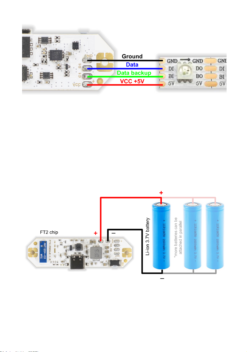
A low resistance of the power lines is critical. Always use thick
(>0.75mm2/20AWG) & very short (<20cm) cables between the FT2
chip and its battery. The voltage drop should be less than 0.1V at full
power. If you need to use any connectors, use only the high current
types like XT60, Deans or EC3.
Powering up
Now that you have connected the digital LED strip and the battery, it
is time to power up the FT2 chip for the first time!
First, connect an USB charger cable to the USB-C connector. If the
attached battery is not yet fully charged, the charging LED should
start pulsing in blue color, indicating a charging process.
Now, press the ON/OFF button for 1 second to power up the chip. If
you have the APA102 LED strip type connected, you should already
see the power up indication (light ramping up) on its LEDs.
If you have the WS2812 or WS2813 LED strip type connected, there
will be no light output yet, the FT2 chip must be configured in the
LtComposer software first.

FT2 chip configuration
Attach the FT2 chip with an USB cable to your computer, make sure it
is turned on and start the LtComposer software (version 3.5+). The
FT2 chip should be detected as connected in the status bar:
Click on the Devices menu at the top, then select the FT2 chip and
click on the Factory config button.
A new window will open, where you can give your FT2 chip its default
name, set the pixel length (resolution), LED strip type and which
digital outputs will be active.
Click Apply to device to save the new configuration into the FT2 chip
and turn it off / on. Your FT2 chip should be now ready to use!
Troubleshooting & FAQ
Problem: the chip seems dead when the ON/OFF button is pressed
and the charging LED is not shining when attached to the USB
charger.
1) Check your battery cables for no short-circuit or reversed polarity.
2) Check that the battery is not faulty, producing a stable voltage in
the range 3.3-4.2V.
Problem: the digital LED strip is not shining at all, or showing
random / white color.
1) Check the connection of DATA / CLOCK wires.
2) Check that the correct digital output (1 or 2) is used.

3) Make sure the LED strip type (APA102 vs. WS2812) matches the
configuration set in LtComposer.
4) Replace / cut the LED strip, the first LED can often be broken.
Problem: when I power on the chip and display some color on the
LED strip at full intensity, the LED strip blinks in red color and the
chip immediately turns off.
1) The battery is empty, attach a 5V USB charger to the FT2 chip
USB-C port and leave it charge to the full, until the blue charging LED
stops pulsing.
2) The battery is undersized and not supplying enough power when
under stress. Use a more powerful battery or several batteries
connected in parallel.
Problem: when I display white color at maximum brightness on the
LED strip, the color changes to dim yellow / orange after a while.
1) The thermal protection of the voltage converter got activated and
reduced the output voltage. Improve the cooling of the chip or
reduce the max brightness in the FT2 configuration window in
LtComposer.
FT2 chip mounting
The FT2 chip can be installed into your target device using the two
2mm mounting holes and M2 sized PCB standoffs (not included):

If you are using metal standoffs, make sure to put M2 nylon washers
from both sides of the chip hole, to prevent a short-circuit of the
neighbor pads.
The FT2 chip can get very hot, especially when used at the maximum
rated output. Never put the FT2 chip into a plastic shrink wrap or
airtight confined space. In some cases, ventilation holes might be
necessary.
Note: FT2 chip contains thermal protection - if the temperature
reaches 100°C, the chip will turn off to protect itself.
Using the external interface
In some projects, you might want to use your own ON/OFF button
and USB connector that are externally mounted and connected to the
chip with hookup wires. In such cases, use the auxiliary connection
pads around the holes:

Connect your external ON/OFF button switch between the BAT+ and
SW pads. Use the push button (tactile) type of switch, not a rocker
type of switch:
Connect a LED diode (forward voltage: 1.7-3.3V) between the LED+
and any GND pad to get an external battery charging indication.
When opting for an external USB-C connector, please make sure the
CC1 and CC2 pins are connected to the ground using two 5.1 KOhm
resistors, otherwise the fast charging capability of the FT2 chip won’t
work. See the connection diagram below:

Power distribution to the LED strips
To get an optimal performance from your FT2 chip application, it is
important to ensure steady voltage across your LED strips.
Digital LED strips rated for +5V voltage (like APA102 and WS2812) are
susceptible to serious voltage losses over longer strip lengths,
leading to poor color fidelity, or no functionality at all. A typical
situation with a longer digital LED strip is shown below:
This problem starts to show with LED digital strips as short as
100-150 pixels. To combat the inevitable voltage drop, run parallel
bypass power cables of sufficient thickness (>0.5mm2/22AWG) from
the VCC and GND pads of the FT2 chip and connect them to the
digital LED strip at several spots along its total run length:
If your project doesn’t allow bypassing along the strip run, try to lead
the power cables at least to the opposite end of the strip:

Radio signal quality
In order to enjoy trouble-free, long range radio communication with
the FT remote, make sure that the FT2 chip is not enclosed in a metal
enclosure and no metal objects are in close proximity to the antenna
area, as shown below:
It is advised that the antenna area is kept at least 5 millimeters from
any plastic enclosure, LED strip, cables, etc.

B) Bypassing the voltage converter
(advanced use case)
For larger LED projects you may find the power of the built-in voltage
converter (40W max) insufficient. In such case, you can completely
omit the DC-DC boost circuit by desoldering 2 components (using a
heat gun set at ~300°C) and bridging two capacitor pads with a solder
blob joint:
Be advised, that without the DC-DC boost converter the quality and
stability of the power supply voltage is now completely up to you.
Please keep in mind that this setup is still limited by the output
MOSFET transistor, whose absolute maximum drain current is ~20A.
C) Using an external 5V power supply
For static installations which run continuously or with large power
consumption, you may want to use a 5 Volt DC power supply instead
of Li-ion batteries. In that case the power supply sources power to
both the FT2 chip and the digital LED strip.
Caution: when using the external DC power supply, leave the VCC
output pins on the FT2 chip unconnected to prevent damage to the
FT2 chip.

A proper wiring scheme using an external DC power supply is shown
below:
Note: In this configuration the voltage converter is not used, so it
doesn’t matter if it is bypassed or not.
Warranty & Disclaimer
The FT2 chip is a highly reliable, yet consumable product, so Pyroterra
Lighttoys doesn’t offer standard warranty for it. Pyroterra Lighttoys
guarantees that the FT2 chip was rigorously tested and functional
when shipped to the customer.
Please understand that the installation of the FT2 chip is at your own
risk. You agree that Pyroterra Lighttoys do not take any responsibility
or liability for the possible damage caused by (mis)use of this product
in your specific application.

Team Pyroterra Lighttoys
wishes you many great moments
with the FT2 technology!
Table of contents
Other Pyroterra Lighttoys Lighting Equipment manuals
Popular Lighting Equipment manuals by other brands

Scanic
Scanic Mini Strobe II instruction manual

Cooper Lighting
Cooper Lighting FAIL-SAFE CFE-4 Series Specification sheet

Chauvet
Chauvet BEAMbar user manual

Gira
Gira 2361 00 operating instructions

Matco Tools
Matco Tools MWL64SMD operating instructions

BARRON
BARRON Exitronix 900E Series installation instructions