QC Industries Automation Series Installation and operating instructions
AS65 Conveyors
Installation & Maintenance Instructions
QC Industries, LLC
4057 Clough Woods Dr.
Batavia, OH 45103 USA
+1 (513) 753-6000
qcconveyors.com
Contents
Warnings 2
Tools 3
Installation 4
Maintenance 11
Recommended Spare Parts 18
Troubleshooting 19
Exploded Views 20
Warranty Information 29
Service Record 32

2AS65 Conveyors | Installation & Maintenance Instructions
Warnings
When used improperly, conveyor
rollers can pinch or maim
Lock out power before servicing
conveyor
Do not use with guards removed Read this manual before operat-
ing
DANGER WARNING WARNING WARNING
Climbing, sitting, walking or riding
on conveyor at any time will cause
severe injury or death
Exposed moving parts can cause
severe injury; DISCONNECT
POWER before removing guard
Equipment may start without
warning - can cause severe injury.
KEEP AWAY
Servicing moving or energized
equipment can cause severe
injury LOCK OUT POWER

AS65 Conveyors | Installation & Maintenance Instructions 3
Tools
uRequired Tools
Set of Metric Wrenches (3mm-
13mm)
Tape Measure 10" Adjustable Wrench Screw Gun and T-30 Torx Bit
Aluminum cutting hack saw or
equivalent
Set of Metric allen wrenches
(3mm, 4mm & ball head 5mm)
Bubble level
uOptional Tools
3/8" Torque wrench QC Industries bearing removal
tool (part# 1A0077A)
Electric Chop Saw
4AS65 Conveyors | Installation & Maintenance Instructions
Installation
uCheck Your Shipment
Before opening the shipment, visually inspect the outside of the crate/box for shipping damage. Carefully unpack the crate/box, inspecting for component damage which
may have occurred inside the packing materials. Contact the carrier and QC Industries regarding any damage that may have occurred during shipment. Check the contents
of your shipment against the supplied packing slip and inform QC Industries of any discrepancies.
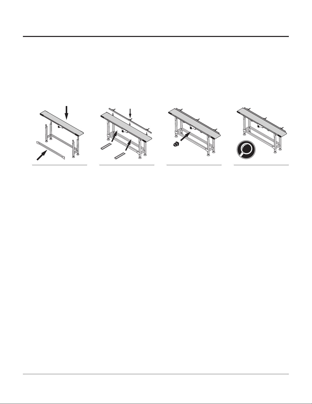
uGeneral Sequence of Installation
1Mount conveyor to stands or
compatible mounting brackets. 2Attach sides, guides or un-
derside idlers to conveyor and
adjust as needed.
3Install drive motor to mount-
ing package. (If not already
installed)
4Lag conveyor to floor / engage
caster locks and inspect
conveyor before use.
uAssistance
If you need assistance, please contact QC Industries customer service department Monday through Friday, 8am-5pm EST at (513) 753-6000. In addition, your local dis-
tributor has been trained at the factory and can provide support in many ways. You can also visit our website - qcconveyors.com - for additional information and technical
documents.
AS65 Conveyors | Installation & Maintenance Instructions 5
Stand Installation
Mounting Aluminum Stands to Conveyor
uMounting Aluminum Exact Width Stands
Stands should be placed as close to ends of conveyor as possible. Stands may be placed a maximum of 10’ apart for conveyors 6” wide or less with a load less than 20
lbs,; conveyors 8”-12” wide with a load less than 25 lbs.; conveyors 18”-24” wide. For all other conveyors, stands should be placed a maximum of 6’ apart.
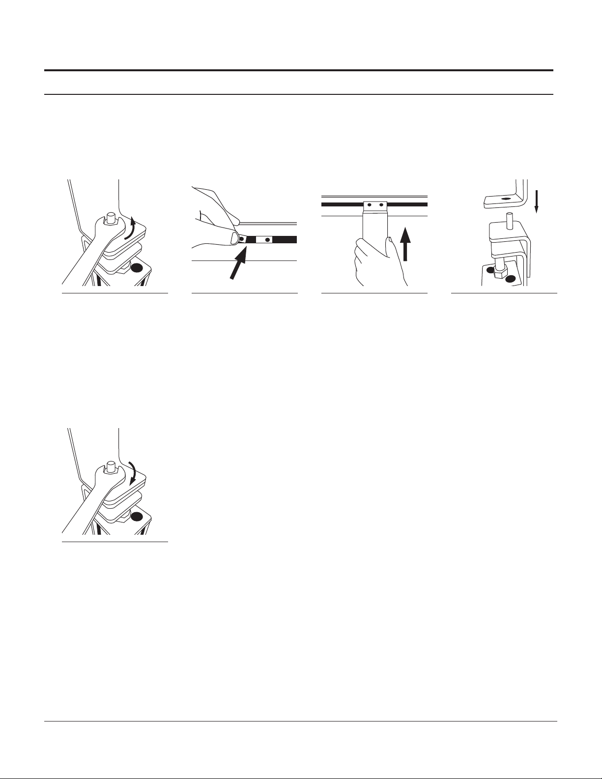
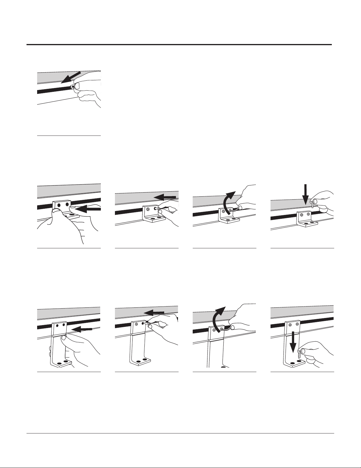
1Remove the nuts holding the
stand attachment brackets to
the top of the stand and remove the
brackets.
2Insert drop in nuts into t-slot
on conveyor frame. 3Attach stand attachment
brackets to conveyor using a
5mm allen wrench.
For Conveyors 6” wide or less:
flange should point outboard;
spacer must be installed between
stand attachment bracket and
conveyor frame.
For conveyors more than 6” wide:
flange should point inboard; no
spacer is necessary
4Place stand attachment
brackets atop stands.
5Replace nuts and tighten.
6AS65 Conveyors | Installation & Maintenance Instructions
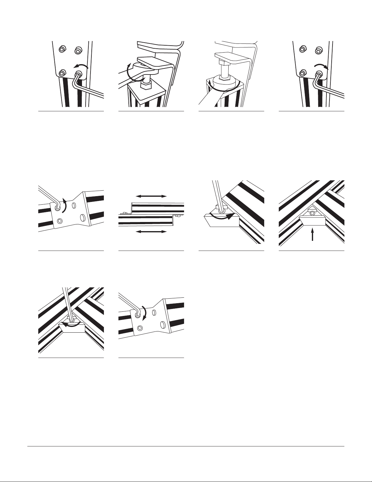
uStand Height Adjustment
1Loosen four screws in each
stand bracket using a 5mm
allen wrench.
2Adjust stand height by
turning bolt using a 3/4”
wrench. Turn clockwise to lower or
counter-clockwise to raise. Ensure
conveyor is level.
3Tighten jam nut against top
plate of stand. 4Tighten four screws in each
stand bracket using a 5mm
allen wrench.
uInstalling Cross Ties
For applications using a single cross tie, the cross tie should be installed between the cross bars of the stands. For applications using two cross ties, the cross ties should
be installed between the uprights of the stands.The installation process is the same for each.
4
x2
x
1Using a 5mm allen wrench,
loosen two socket head cap
screws in each cross tie adjustment
plate.
2Slide adjustable cross tie
pieces to fit between stands. 3Loosen triangular Quick Clamp
on each end of cross tie. 4Ensuring the socket head cap
screw is facing you, slide Quick
Clamp into tee slot at desired mount-
ing position.
4
x
5Using a 5mm allen wrench,
tighten Quick Clamp. 6Using a 5mm allen wrench,
tighten two socket head cap
screws in each cross tie adjustment
plate.

AS65 Conveyors | Installation & Maintenance Instructions 7
uMounting Angle Braces
2
x2
x2
x
1Insert two drop in nuts into
inner stand leg t-slots. 2Insert drop in nuts into
conveyor frame’s t-slot. 3Align angle brace over drop
in nuts in stand. 4Insert socket head cap screws
through angle brace and into
drop in nuts on stand (do not fully
tighten).
2
x
2
x
2
x
5Slide up and align angle
brace with drop in nuts in
frame.
6Insert socket head cap screws
through angle brace and into
nuts in conveyor frame.
7Tighten socket head cap
screws on frame. 8Tighten socket head cap
screws on stand.
9Check with bubble level to
ensure conveyor is level.
>Repeat for opposite side.
Injury is possible if the stands are not lagged to the oor, cross ties are not used, or angle braces are not present. Never place a conveyor in operation until all proper
mounts are installed and secured.
Warning: Moving conveyors with casters can create dynamic forces that could tip the conveyor. Use caution when moving a conveyor with casters.
8AS65 Conveyors | Installation & Maintenance Instructions
Mount Installation
Ensure mount placement on mounting surface allows clearance for drive package.
2
x
1Insert drop in nuts into t-slot.
>Proceed to correct mounting type.
uFlush Mount
2
x2
x2
x
1Line up mount to drop in nuts. 2Insert socket head cap
screws through mount and
into drop in nut.
3Tighten screws to secure
mount to frame. 4Insert screws (not provided)
into desired mounting surface
and tighten.
uRaised Mount
Mounts’ foot can be placed facing inward or outward depending on application.
1Line up mount to drop in nuts. 2Insert socket head cap
screws through mount and
into drop in nut.
3Tighten screws to secure
mount to frame. 4Insert screws (not provided)
into desired mounting surface
and tighten.
AS65 Conveyors | Installation & Maintenance Instructions 9
Side /Guide Installation
Guide brackets can not be placed over drive assembly mounting brackets.
uInstalling Fixed Side Rails
2
x
1Insert drop in nuts into t-slot
on frame. 2Align guide brackets with
drop in nuts. 3Insert socket head cap screw
through guide clamp and into
drop in nuts.
4insert two drop in nuts into
t-slot at tail end of frame.
2
x2
x
5Align clamping block to drop
in nuts. 6Insert screws through clamp-
ing block and into drop in
nuts.
7Loosen tracking block screws.
(Do not remove) 8Slide guide rail in between
clamps and frame until in
place.
2
x2
x
9Tighten screws in clamping
blocks. 10Tighten screws in guide
clamps. 11Retighten screws in track-
ing block.
If sides have seals, speed of conveyor should be no faster than 30 feet per minute.
Side seals are designed for use with MAA Standard Urethane Belts.

10 AS65 Conveyors | Installation & Maintenance Instructions
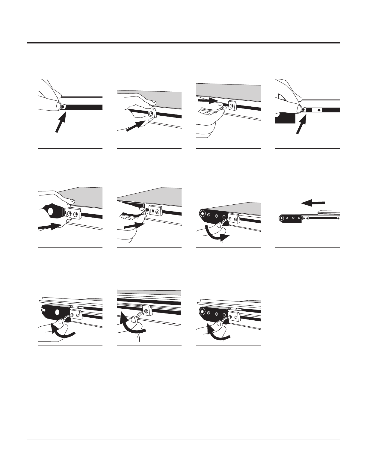
uInstalling Adjustable Guide Brackets
2
x
1Insert economy nuts into
t-slot of guiderail and slide
into position
2Loosely thread adjusting rod
into nuts. 3Place a cross block onto
each guiderail and set aside. 4Insert drop in nuts into t-slot
on frame.
2
x
2
x
5Align guide bracket, keeping
the larger hole up, with drop
in nuts and insert screws.
6Tighten socket head cap
screws. 7Insert a rod vertically through
the larger hole on top of
guide bracket.
8Secure rod from below with
socket head cap screw.
9Tighten cap screw. 10Slide guiderail assembly
over vertical rods on
frame.
11Adjust guides to desired
width and tighten rods. 12Tighten screw on cross
block to secure rod.
13Install guiderail and block
assembly over vertical
rods and adjust to desired height.
(Guide should NOT touch belt)
This manual suits for next models
1
Table of contents
Other QC Industries Accessories manuals


