Qomo QIT1375 User manual

Interactive Touch Screen
User Manual
Please properly keep the manual for further reference. This is the general user manual for all
interactive touch screens. Therefore, it may be different from the actual product.

Welcome:
Thanks for purchasing this product. Please read the instructions carefully before using this product.
This device complies with part 15 of the FCC Rules. Operation is subject to the following two conditions:
(1) This device may not cause harmful interference, and
(2) This device must accept any interference received, including interference that may cause undesired
operation.
This equipment has been tested and found to comply with the limits for a Class B digital device, pursuant
to part 15 of the FCC Rules. These limits are designed to provide reasonable protection against harmful
interference in a residential installation. This equipment generates, uses and can radiate radio frequency
energy and, if not installed and used in accordance with the instructions, may cause harmful interference
to radio communications. However, there is no guarantee that interference will not occur in a particular
installation. If this equipment does cause harmful interference to radio or television reception, which can
be determined by turning the equipment off and on, the user is encouraged to try to correct the
interference by one or more of the following measures:
●Reorient or relocate the receiving antenna.
●Increase the separation between the equipment and receiver.
●Connect the equipment into an outlet on a circuit different from that to which the receiver is connected.
●Consult the dealer or an experienced radio/ TV technician for help.
The symbol of the crossed out wheeled bin indicates this product should not be placed
in municipal waste. Instead, you need to dispose of the waste equipment by handing it
over to a designated collection point for the recycling of waste electrical and
electronic equipment.

Content
Safety Instruction.........................................................................................................................................1
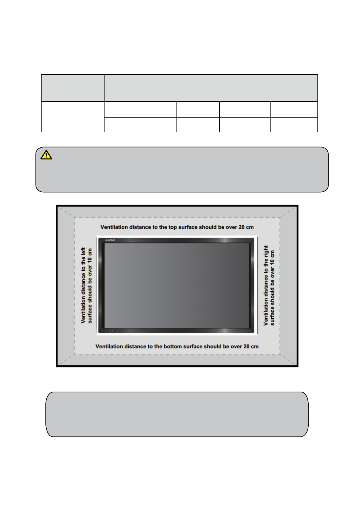
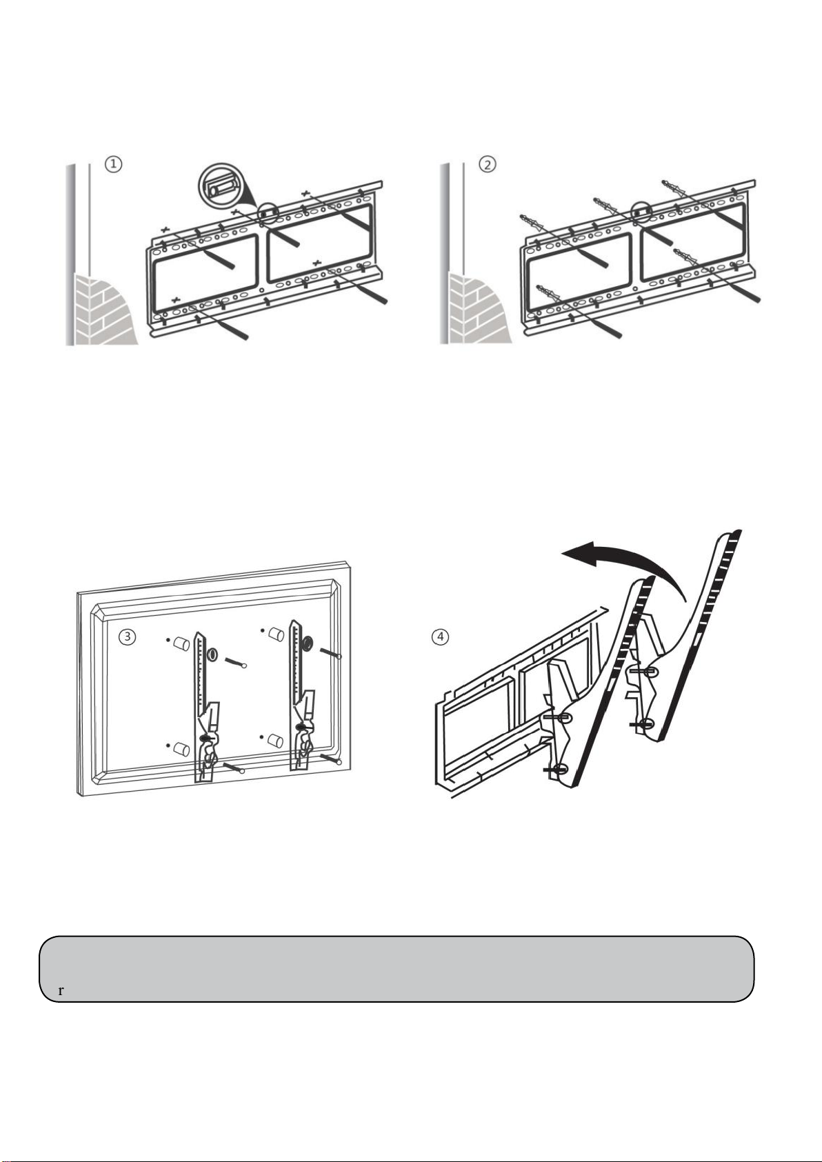
Installation....................................................................................................................................................3
Introduction..................................................................................................................................................6
Basic Operation............................................................................................................................................7
Power on ..................................................................................................................................................7
Power off..................................................................................................................................................7
OPS Installation .......................................................................................................................................8
Remote Control ............................................................................................................................................9
Functions of remote control.....................................................................................................................9
Instructions of remote control................................................................................................................10
Buttons & Ports..........................................................................................................................................11
Buttons & ports on the front panel.........................................................................................................11
Ports on the rear panel for 65” & 75” ....................................................................................................12
Ports on the rear panel for 86” ...............................................................................................................12
RS232 code list ......................................................................................................................................13
Operation Interface ...................................................................................................................................17
Android Home Page...............................................................................................................................17
Android Settings ....................................................................................................................................19
Built-in PC Interface..............................................................................................................................25
Other Source Settings ............................................................................................................................25
Bottom-up Toolbar.................................................................................................................................26
Annotation software - MagicBoard .......................................................................................................27
Included Accessories ..................................................................................................................................31
Troubleshooting..........................................................................................................................................32

1
Safety Instruction
For your safety, please read the following instruction before you use the product. Serious injury or
property loss may be caused by improper operations. Do not try to repair the product by your own.
WARNING
Disconnect the product from power supply immediately if major failures occur.
The major failures include the following:
Smoke, peculiar smell or abnormal sound is discharged from the product.
No image or sound is displayed, or the image error occurs.
Where the mains plug or an appliance coupler is used as the disconnect device,
such disconnect device shall remain readily operable.
In the preceding scenarios, do not continue to use the product, disconnect power supply
immediately and contact professional staff for troubleshooting.
Do not drop liquid, metal or combustible into the product.
If any liquid or metal is dropped into the product, power off the product and
disconnect power supply, then contact professional staff for solutions.
Pay attention to the children when they are close to the product.
Do not damage the power cable.
●Do not damage, change, wind, bend, heat or drag the power cable forcibly.
●Do not put weights (such as the product itself) on the power cable.
●Do not drag the cable forcibly when you pull out the power plug. If the power cable is
damaged, please contact the local distributor to repair or replace it.
Put the product on a stable surface.
An unstable surface includes and does not limit to an inclined plane, a shaky stand, desk
or platform, which might cause the turnover and damage.
Use the battery correctly.
Galvanic corrosion, electric leakage and even fire may be caused by improper battery
usage.
It is recommended to use the designated type of battery and install the battery by
correct electrodes (positive and negative electrodes).
Do not install and use new battery with the used one.
Take out the battery if the remote control is not used for a long period.
Do not expose the battery under overheated environments such as sunlight and firing.
Dump the used battery based on local regulations.
WARNING
Do not open the cover or change the product by your own.
High voltage components are installed in the product. When you open the cover, high
voltage, electric shock or other dangerous situations may occur. If inspection, adjustment
or maintenance is required, contact the local distributor for help.

2
Use the specified power supply.
● Do not use any types of power cables other than the one provided with the product to
prevent the product from being damaged.
● Use a three-wire socket and ensure that it is properly grounded.
● Pull out the power plug from the socket if the product is not used for a long period.
Before you move the product, disconnect all external connections and separate all
toppling preventing devices.
Move the product carefully to prevent it from being hit or squeezed, especially the screen,
which may cause injury if broken.
Clean the dust and metal on the power plug regularly.
●When you are cleaning, fire or electric shock may be caused if the product is powered
on.
●Keep in mind to pull out the power plug before cleaning it by using a dried cloth.
Do not put items on the top of the product.
●Do not put items, such as a container for liquid (a vase, flowerpot, cosmetics or liquid
medicine), on the top of the product.
●If any water or liquid is spilled on the product, short circuit may occur and cause fire
or electric shock.
●Do not tread on the product or hang any items on the product.
Do not install the product in an improper place.
●Do not install the product in humid places, such as the bathroom, the shower room,
the place near windows or outdoor environments where experience rain, snow or other
harsh weather. The product installation is also required to avoid a place around by hot
spring vapor. The preceding environments may cause faults or electric shock under
extreme conditions.
●Do not put exposed fire source, such as an ignited candle, on the product.
Pull out the power plug during thunderstorms.
● Do not touch the product when lighting to avoid electric shock.
● Install or place components which power supply voltage is high enough to cause
personal injury in places out of the reach of children.
WARNING
Do not cover or block up any vents on the product.
●The overheated components may cause fire, damage the product and shorten the
service life.
●Do not put the venting surface of the product facedown.
●Do not use a cloth such as table cloth to cover the product.
Do not touch the power cable with wet hands to avoid electric shock.
CAUTION

3
Do not install the product in high temperature environments.
●Do not install the product near heat source, such as the radiator, the heat reservoir, the
stove or other heating devices.
●Do not expose the product under sunlight, which may cause high temperature and
subsequent faults in the product.
For transport:
●Pack the product for mobility or maintenance by using the cartons and cushioning
material provided with the product.
●Vertically move the product during transport. The screen or other components are
easily broken if the product is moved by an improper way.
Keep away from the product when you use a radio.
The product design to prevent radio interference complies with the international EMI
standard. However, the interference still exists and causes noise in the radio.
●If noise occurs in the radio, try the following solutions.
●Adjust the direction of the radio antenna to avoid the interference from the product.
●Keep the radio away from the product.
Advice for watching:
●Use the product in an environment with comfortable light. It is harmful to your eyes to
watch in a too bright or too dark environment.
●Relax your eyes after a period of time for watching.
●When you are watching, the distance which is 3 to 7 times of the screen height should
be kept, and it is the best distance to protect eyes and prevent eyestrain.
●Adjust the volume to an appropriate level, especially at night.
Installation
Bearing
You can install the product in an unfixed or a wall-mounted way based on your needs. The wall-mounted
way can save a large amount of space.
If the product is installed in an unfixed way, use the designated hanger or holder. If you want to use a
self-made hanger or holder, ensure that the bearing capacity of it is at least four times of the weight of
the product, and the product is installed stably on it.
If the product is installed in a wall-mounted way, the bearing capacity of the surface for installation
must be at least four times of the weight of the product. If the surface for installation is the wall or the
ceiling of a building, the surface must be made of solid bricks, concrete or other materials with equal
intensity. If the product is installed on a surface made of loose material such as an old brick wall, wood
plank wall, solid brick wall, or a metal or non-metal structure surface, or a surface with a thick

4
decoration layer, take necessary consolidating measures to ensure that the product is stably installed.
Ventilation
Ventilation
requirements
Distance to the surface for installation (cm)
Nominal power
Greater than 100 W
Left and right sides
Top
Bottom
Back
10
20
20
10
If the product is installed inside a wall or a cabinet, in addition to the preceding requirements,
the ventilation area around the bottom, top and two sides must be at least 50% of the sealing
surface to ensure proper ventilation.
Note: 1. When the product is installed in a wall-mounted way, the screws need to be
installed deeper than 10 mm in the way.
2. Do not block ventilation vents.
Operation Interface

5
Installation diagram
Note: The horizontal and vertical distance of mounting holes on the back of screen must be within the
required distance of bracket.
Use a level to locate the holes in
horizontal line and mark with pencil
where the holes will be located. Then
drill holes in the wall.
Insert wall plugs into the mounting holes.
Push the self-tapping screws through the
bracket into the wall plugs and tighten the
screws.
Attach the mounting arms to the
back of screen with the screws.
Hang the screen and let it settle into the
bracket. Ensure that it is firmly in place.
Level
Operation Interface

6
Introduction
As our latest independently developed and produced human-machine interactive product, the Journey
13 series interactive touch screen is a multi-functional display for interactive teaching, digital
demonstration, multi-media presentation, touch operations and handwriting. They are well designed and
produced to meet the needs of education and corporate applications, and provide a user-friendly
experience, digital intelligent control as an ideal equipment for schools and companies. You can use
your fingers or opaque objects to write, edit and delete any things on the screen.
The product features are as follows:
•Specially designed for teaching and meeting systems.
•With high brightness and high contrast, the display is visible under strong sunlight or in outdoor
environments.
•Enter into Eco mode with one-touch button to reduce the power consumption.
•Adopt advanced infrared array scanning and sensing technology, HID driver-free, meaning the
product is activated soon after it is powered on.
•Multi-signal sources can be previewed in the window and be switched by touching the screen.
•Vector-based image-editing software with features like high compression and distortion free.
•Multiple pen tools, line styles and colors selections.
•Support real time on-screen editing.
•Shape recognition turns hand-drawn shapes into perfect versions.
•Save files in various formats, including PDF, JPEG, PNG, BMP and etc.
•Multi-touch screen enables several users use the screen together.
•User management enables you to add a new user, delete a user, switch a user and edit user
information etc.
•Support handwriting recognition including English, Chinese, numbers and special characters.

7
Basic Operation
Power on
Power the interactive touch screen with the 100V-240V 50Hz/60Hz AC power supply.
Connect the panel to the power supply. Switch on the rocker switch (on the left bottom of the rear
of the panel, next to the power port) to enter standby status. The power indicator turns red.
Press power button on the control panel or Power on the remote control to turn on the display and
built-in PC simultaneously. The power indicator turns green.
Power off
Press ECO on the control panel to temporarily turn off the display.
Press power button on the control panel or Power on the remote control to enter the standby status.
The power indicator turns red.
In the standby status, switch off the rocker switch to turn off the touch screen.
1. Disconnect the touch screen from power after the touch screen enters standby status.
Otherwise, the screen may be damaged. A sudden power failure may damage the touch
screen.
2. Frequent power on and off in a short time may cause faults.
Status of the power indicator is as follows:
Power Indicator
Status
No light
Power off
Red
Standby
Green
Power on

8
OPS Installation
The OPS does not support hot-plugging. Please insert the plug of the OPS after the
interactive panel is disconnected from the power.
Install the OPS by following the following steps:
Step 1: Insert the OPS into the special slot on the rear of the interactive panel.
Step 2: Tighten the screws.
Step 3: Confirm that the OPS is installed correctly.
Handle facing outward

9
Remote Control
Functions of remote control
1. Power on or standby
2. Mute
3. Change channels or enter numbers
4. Return
5. P. MODE: Picture mode
SMODE: Sound mode
6. Signal source selection
7. Show the current signal source
8. VOL+/ VOL-: Increase/decrease volume
9. CH+/ CH-: Change channel
10. Sleep mode
NICAM: Select the sound tracks
ASPECT: Selects picture aspect
EPG: Electronic program guide
11. Up/down/right/left direction buttons
OK: Confirm
12. Show or hide menu
13. Quit the current interface
14. Play/Pause
15. Rewind or replay certain scenes
16. Buttons for image & text editing
17. Buttons for channel editing

10
Instructions of remote control
The usage scope of the remote control includes the vertical distance within five meters in front of the
panel, and the area within an angle of 30 degrees from the vertical point to the left and right.
The effective receiving area is about 3 meters with 30° angle from vertical point to the left and right. And
the effective receiving area is about 5 meters from the front of device. Note that the remote control signal
receiver locates at the position of power indicator.

11
Buttons & Ports
Buttons & ports on the front panel
Decrease volume OSD button:
Increase volume OSD button:
Android USB port
Built-in PC USB port
HDMI port used to connect an
external display device
Power indicator:
Press power switch on the control
panel. The power indicator turns green.
Press power switch on the control
panel to enter the standby status. The
power indicator turns red.
Enter/Return to Android home page
Front ports:
Return to previous interface
Enter ECO mode to turn off the display
Enter/Exit the OSD menu
Enter/Exit signal source menu
Power switch: on or standby

12
Ports on the rear panel for 65” & 75”
Ports on bottom of mainboard
Ports on side of mainboard
Ports on the rear panel for 86”
Ports on side of mainboard
Ports on bottom of mainboard

13
RS232 code list
There are two RS232 code lists. Please refer to corresponding list according to your panel model.
RS232 Code List for 65” & 75”
6 bytes command Baud rate: 115200 Data bits: 8 Check bit: none
Start code 99, Customer code (Public Version: XX = 23), Function ID code, Device ID code(It is
generally 01, unless otherwise noted), Check code + Function ID code = FF, End code AA.
HOME
|99 XX 00 01 FF AA
Power Off
|99 XX 01 01 FE AA
Power On
|99 XX 80 01 7F AA
Mute
|99 XX 02 01 FD AA
Sound Mode
|99 XX 03 01 FC AA
Image Mode
|99 XX 04 01 FB AA
ATV
|99 XX 07 01 F8 AA
DTV
|99 XX 05 01 FA AA
Video
|99 XX 08 01 F7 AA
Component
|99 XX 0A 01 F5 AA
Computer 1
|99 XX 0B 01 F4 AA
Computer 2
|99 XX 0C 01 F3 AA
Computer 3
|99 XX 0D 01 F2 AA
Computer 4
|99 XX 06 01 F9 AA
HDMI1
|99 XX 0E 01 F1 AA
HDMI2
|99 XX 0F 01 F0 AA
Front Computer
|99 XX 10 01 EF AA
Built-in Computer
|99 XX 11 01 EE AA
DP
|99 XX 09 01 F6 AA

14
Menu
|99 XX 12 01 ED AA
Signal Source
|99 XX 13 01 EC AA
Exit
|99 XX 14 01 EB AA
Listen only audio
|99 XX 15 01 EA AA
Volume +
|99 XX 17 01 E8 AA
Volume -
|99 XX 18 01 E7 AA
Channel +
|99 XX 19 01 E6 AA
Channel -
|99 XX 1A 01 E5 AA
Screenshot
|99 XX 1B 01 E4 AA
Screen Display
|99 XX 1C 01 E3 AA
Display ratio
|99 XX 1E 01 E1 AA
Sleep Mode
|99 XX 1D 01 E2 AA
Auto Adjustment
|99 XX 1F 01 E0 AA
Up
|99 XX 22 01 DD AA
Down
|99 XX 23 01 DC AA
Left
|99 XX 24 01 DB AA
Right
|99 XX 25 01 DA AA
Confirm
|99 XX 26 01 D9 AA
Multi-media
|99 XX 27 01 D8 AA
Device Status Query
|99 XX 28 01 D7 AA
1. Status Query Feedback 8 byte data
Start code 99, Board card model, Power On, Current channel, Volume, Sound mode, Check code
(Current channel + Volume + Sound mode), End code AA

15
1. Boar card model 01
2. Power on: 01
3. Current channel:
Computer 1 = 0B, Computer 2 = 0C, Computer 3 = 0D, Computer 4 = 06, ATV = 07, DTV = 05,
Video = 08, Aberration = 0A, HDMI1 = 0E, HDMI2 = 0F, DP= 09, Front computer = 10, Built-in
computer = 11, Multi-media or Application state of third party = 0E
4. Volume: 0~100 (decimal) = 0~64 (hexadecimal), mute state = 65
5. Sound mode :Standard = 01, Music = 02, Movie = 03, Sports = 04,
User = 05, Immersive 1 = 06, Immersive 2 = 07
E.g.:99 01 01 0C 32 03 41 AA
Note: Power off state without any feedback.
RS232 Code List for 86”
RS232 Setting: Baudrate: 115200 bps; Parity check: no parity; Stop bit: one; Data bit: 8 bits;
RS232 Packet1
(Packet size : 8
bytes)
0
1
2
3
4
5
6
7
HEADER1
HEADER2
HEADER3
CMD1
CMD2
DATA1
DATA2
DATA3
0x55
0x54
0x53
0xXX
0xXX
0xXX
0xXX
0xXX
Command List
FUNCTION
HEADER1
HEADER2
HEADER3
CMD1
CMD2
DATA1
DATA2
DATA3
Start Panel remotely
0x55
0x54
0x53
0x50
0x4E
0x21
0x21
0x21
Shutdown panel
remotely
0x55
0x54
0x53
0x50
0x46
0x21
0x21
0x21
Get Signal Source
(bidirectional)
0x55
0x54
0x53
0x50
0x53
0x21
0x21
0x21
Set Signal Source
(DTV)
0x55
0x54
0x53
0x50
0x73
0x21
0x21
0x21
Set Signal Source
(ATV)
0x55
0x54
0x53
0x50
0x73
0x21
0x21
0x21
Set Signal Source
(Video 1)
0x55
0x54
0x53
0x50
0x73
0x30
0x30
0x21
Set Signal Source
(Video 2)
0x55
0x54
0x53
0x50
0x73
0x30
0x31
0x21
Set Signal Source
(Component)
0x55
0x54
0x53
0x50
0x73
0x30
0x32
0x21
Set Signal Source
(HDMI 1)
0x55
0x54
0x53
0x50
0x73
0x30
0x33
0x21
Set Signal Source
(HDMI 2)
0x55
0x54
0x53
0x50
0x73
0x30
0x34
0x21
Set Signal Source
(PC1)
0x55
0x54
0x53
0x50
0x73
0x30
0x35
0x21
Set Signal Source
(PC2)
0x55
0x54
0x53
0x50
0x73
0x30
0x36
0x21
Set Signal Source
(S terminal)
0x55
0x54
0x53
0x50
0x73
0x30
0x37
0x21
Set Signal Source
(Built-in HDMI)
0x55
0x54
0x53
0x50
0x73
0x30
0x38
0x21
Set Signal Source
(External HDMI)
0x55
0x54
0x53
0x50
0x73
0x30
0x39
0x21
Get Display Mode
(Bidirectional)
0x55
0x54
0x53
0x50
0x44
0x31
0x30
0x21
Set Display Mode
(16:9)
0x55
0x54
0x53
0x50
0x64
0x31
0x31
0x21
Set Display Mode
(4:3)
0x55
0x54
0x53
0x50
0x64
0x21
0x21
0x21
Set Display Mode
(Figure Mode)
0x55
0x54
0x53
0x50
0x64
0x30
0x21
0x21

16
Set Display Mode
(Full View Mode)
0x55
0x54
0x53
0x50
0x64
0x31
0x21
0x21
Set Display
Mode(Subtitle Mode)
0x55
0x54
0x53
0x50
0x64
0x32
0x21
0x21
Set Display
Mode(Movie Mode)
0x55
0x54
0x53
0x50
0x64
0x33
0x21
0x21
Get Display Mode
(bidirectional)
0x55
0x54
0x53
0x50
0x50
0x34
0x21
0x21
Set Image
Mode(Standard)
0x55
0x54
0x53
0x50
0x70
0x35
0x21
0x21
Set Image
Mode(Bright)
0x55
0x54
0x53
0x50
0x70
0x21
0x21
0x21
Set Image Mode(Soft)
0x55
0x54
0x53
0x50
0x70
0x30
0x21
0x21
Set Image
Mode(Customized)
0x55
0x54
0x53
0x50
0x70
0x31
0x21
0x21
Get Sound Mode
(bidirectional)
0x55
0x54
0x53
0x50
0x41
0x32
0x21
0x21
Set Sound Mode
(Standard)
0x55
0x54
0x53
0x50
0x61
0x33
0x21
0x21
Set Sound Mode
(Music)
0x55
0x54
0x53
0x50
0x61
0x21
0x21
0x21
Set Sound Mode
(News)
0x55
0x54
0x53
0x50
0x61
0x30
0x21
0x21
Set Sound Mode
(Movie)
0x55
0x54
0x53
0x50
0x61
0x31
0x21
0x21
Set Sound Mode
(Customized)
0x55
0x54
0x53
0x50
0x61
0x32
0x21
0x21
Get Volume
(bidirectional)
0x55
0x54
0x53
0x50
0x56
0x33
0x21
0x21
Set Volume(000-100)
0x55
0x54
0x53
0x50
0x76
0x34
0x21
0x30~0x39
Get Channel
(bidirectional)
0x55
0x54
0x53
0x50
0x43
0x21
0x21
0x21
Set Channel(000-999)
0x55
0x54
0x53
0x50
0x63
0x30~0x31
0x30~0x3
9
0x30~0x39
Screen brighten
0x55
0x54
0x53
0x50
0x42
0x21
0x21
0x21
Screen darken
0x55
0x54
0x53
0x50
0x62
0x30~0x39
0x30~0x3
9
0x21
Mute
0x55
0x54
0x53
0x50
0x4D
0x21
0x21
0x21
Channel+
0x55
0x54
0x53
0x50
0x3E
0x21
0x21
0x21
Channel-
0x55
0x54
0x53
0x50
0x3C
0x21
0x21
0x21
Volume+
0x55
0x54
0x53
0x50
0x2B
0x21
0x21
0x21
Volume-
0x55
0x54
0x53
0x50
0x2D
0x21
0x21
0x21
Menu
0x55
0x54
0x53
0x50
0x6D
0x21
0x21
0x21
Signal Source
0x55
0x54
0x53
0x50
0x58
0x21
0x21
0x21
Up(keyboard)
0x55
0x54
0x53
0x50
0x55
0x21
0x21
0x21
Down(keyboard)
0x55
0x54
0x53
0x50
0x44
0x21
0x21
0x21
Left (keyboard)
0x55
0x54
0x53
0x50
0x4C
0x21
0x21
0x21
Right(keyboard)
0x55
0x54
0x53
0x50
0x52
0x21
0x21
0x21
Ok(Keyboard)
0x55
0x54
0x53
0x50
0x4F
0x21
0x21
0x21
Back Button
0x55
0x54
0x53
0x50
0x45
0x21
0x21
0x21
Home button
0x55
0x54
0x53
0x50
0x48
0x21
0x21
0x21

17
Operation Interface
Android Home Page
Android home page provides preview function that displays three parts. Click on the toolbar or
Press HOME button to enter the home page.
1. Click the signal source in part ① and its thumbnail will be shown in part ②. Then click part ② to
enter its corresponding signal source.
2. Part ③ includes four icons Settings, Chrome Browser, Applications and Explorer. Click the icon to
enter its corresponding interface.
Settings: Click the icon to enter the Android setting interface.
1
2
3
This manual suits for next models
1
Table of contents
Other Qomo Touch Panel manuals