QSC K.2 series User manual

Product Models: K8.2, K10.2, K12.2
Document #: TD-001517-01
Initial Release: March 2018
Revised Release:
Revision: A
Service Manual
QSC, LLC
Costa Mesa, California, USA
www.qsc.com
K.2 Series

2QSC, LLC

3
TD-001517-01
K.2 Series Service Manual
Table of Contents
1. Introduction..................................................................................................................................................................................5
1.1 Restriction of Hazardous Substances Directive (RoHS) ...................................................................................................................................................... 5
1.2 Revision history......................................................................................................................................................................................................................... 5
1.3 Service manual contents.......................................................................................................................................................................................................... 5
1.4 Service bulletins ........................................................................................................................................................................................................................ 5
1.5 Serial Numbers.......................................................................................................................................................................................................................... 6
1.6 Required equipment for service ............................................................................................................................................................................................. 6
2. Product specification and images ................................................................................................................................................7
3. Firmware & software....................................................................................................................................................................8
3.1 Firmware revision history ....................................................................................................................................................................................................... 8
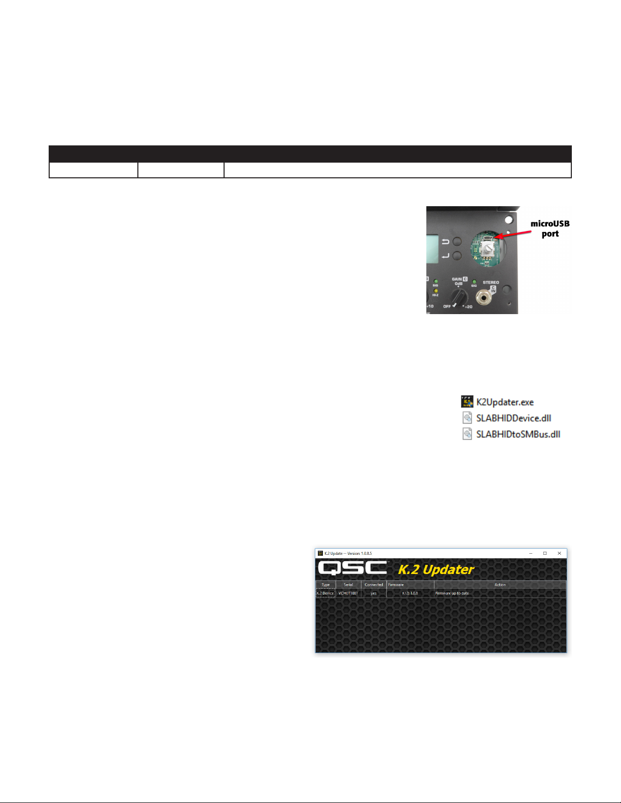
3.2 Firmware update instructions................................................................................................................................................................................................. 8
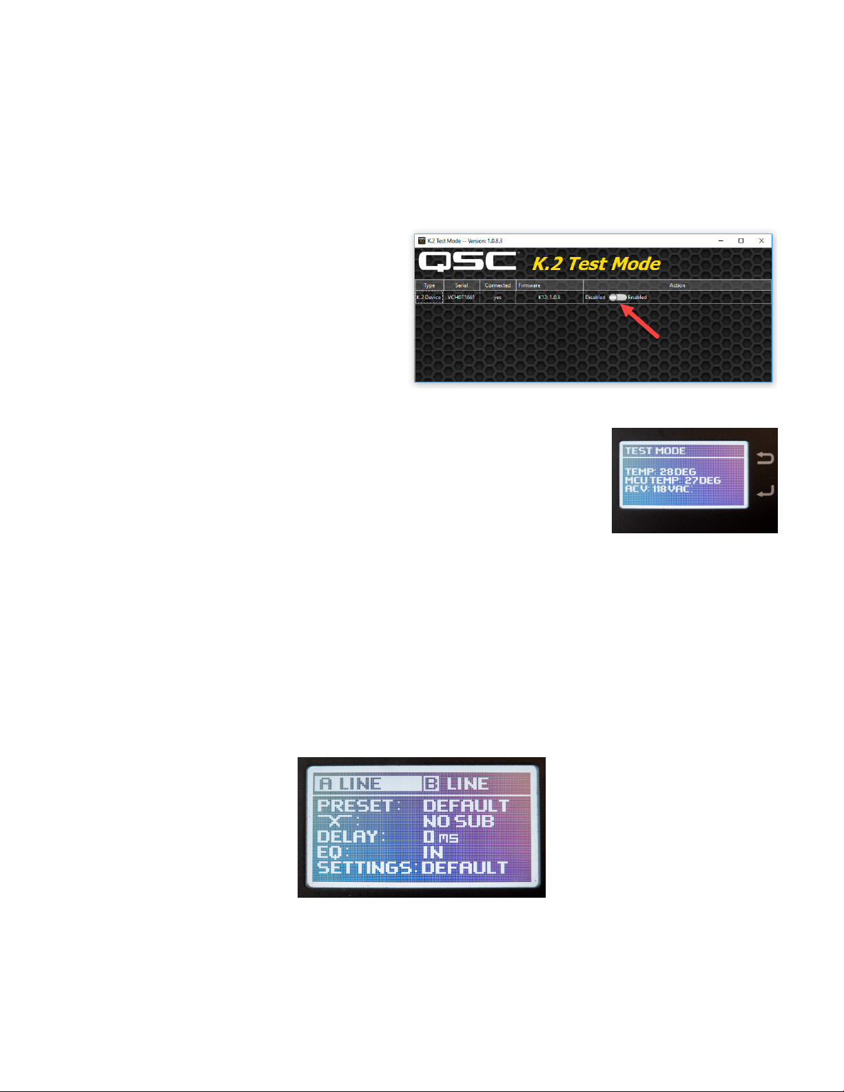
3.3 Test Mode application.............................................................................................................................................................................................................. 9
4. Operational description ............................................................................................................................................................. 11
4.1 Series description.....................................................................................................................................................................................................................11
4.2 Model descriptions..................................................................................................................................................................................................................11
4.3 Amplifier module.....................................................................................................................................................................................................................12
5. Loudspeaker disassembly & repair instructions ....................................................................................................................... 17
5.1 Amplifier module .....................................................................................................................................................................................................................17
5.2 Front grille ................................................................................................................................................................................................................................19
5.3 Front baffle...............................................................................................................................................................................................................................19
5.4 High frequency transducer.................................................................................................................................................................................................... 20
5.5 Low frequency transducer .....................................................................................................................................................................................................21
5.6 Handles, feet, and pole mount..............................................................................................................................................................................................21
6. Amplifier module disassembly & repair instructions ...............................................................................................................23
6.1 Back cover................................................................................................................................................................................................................................ 23
6.2 AMP/PSU board...................................................................................................................................................................................................................... 24
6.3 Input/DSP board..................................................................................................................................................................................................................... 27
6.4 LCD board................................................................................................................................................................................................................................ 28
6.5 EMI shield and AC line filter board...................................................................................................................................................................................... 28
6.6 Fan ............................................................................................................................................................................................................................................ 30
6.7 Amplifier module reference...................................................................................................................................................................................................31
7. Testing.........................................................................................................................................................................................32
7.1 Requirements........................................................................................................................................................................................................................... 32
7.2 Amplifier module testing........................................................................................................................................................................................................ 33
7.3 Loudspeaker testing................................................................................................................................................................................................................ 36
8. Troubleshooting tips...................................................................................................................................................................38
8.1 General tips.............................................................................................................................................................................................................................. 38
8.2 Testing the AC mains fuse and line filter components...................................................................................................................................................... 39
8.3 Bypassing the AC line filter ................................................................................................................................................................................................... 40
8.4 Power supply MOSFETs and repair.......................................................................................................................................................................................41
8.5 Amplifier MOSFETs................................................................................................................................................................................................................. 42
8.6 LF and HF amplifier LEDs...................................................................................................................................................................................................... 43
8.7 +12VLOW voltage rail failures............................................................................................................................................................................................... 43
8.8 Testing the input/DSP and LCD boards ............................................................................................................................................................................... 44
8.9 LCD ribbon............................................................................................................................................................................................................................... 45
8.10 Input section failure.............................................................................................................................................................................................................. 46
8.11 Fan issues and overheating................................................................................................................................................................................................. 46
8.12 Front LED................................................................................................................................................................................................................................ 47
8.13 Internal wiring harness......................................................................................................................................................................................................... 47
8.14 Transducer issues.................................................................................................................................................................................................................. 48
9. Schematics, exploded-view drawings, and BOM ......................................................................................................................49

4QSC, LLC
QSC, LLC
Technical Services Group
1675 MacArthur Blvd.
Costa Mesa CA 92626 USA
K.2 Series Service Manual
Copyright © 2018 by QSC, LLC. All Rights Reserved.
QSC and the QSC logo are trademarks of QSC, LLC in the U.S. Patent and Trademark Office and other countries. Patents
may apply or be pending.
Windows® is a registered trademark of Microsoft Corp.
Audio Precision® is a registered trademark of Audio Precision, Inc.
All other trademarks are property of their respective owners.
+1 (714) 957-7150
1-800 QSC AUDIO (USA only)
+1 (714) 754-6173 (fax)
www.qsc.com (main web site)
www.qsc.com/login (Service Partner Portal login)
www.qscparts.com (parts and accessories sales)

5
TD-001517-01
K.2 Series Service Manual
1. Introduction
1.1 Restriction of Hazardous Substances Directive (RoHS)
QSC K.2 Series powered loudspeakers are manufactured to conform to the European Union’s RoHS Directive, which reduc-
es the amount of hazardous substances allowed in products for sale within its member nations. In electronic equipment
such as audio processors, this applies primarily to certain toxic heavy metals, such as lead, which may be present in elec-
tronic components, solder, and other parts.
RoHS-compliant materials
When servicing RoHS-compliant electronic products, it is important for the service technician to use only RoHS-compliant
components and solder (lead-free). All replacement parts provided by QSC for RoHS-compliant products are certified as
RoHS compliant.
RoHS-compliant tools
Soldering irons and desoldering apparatus used on RoHS-compliant products must also not be contaminated by hazardous
substances, such as lead. Therefore, you cannot use the same soldering and desoldering tools for RoHS-compliant products
and solder as you do for non-compliant products and solder. You must either use separate soldering irons, desoldering tools
and braid, etc., or at the very least designate separate tips and braids and use only the appropriate ones. If you contami-
nate a tip or braid, even inadvertently, by using it on a non-compliant product or solder, you should no longer use it with
RoHS-compliant products or solder.
1.2 Revision history
No revision history yet. First revision released March 2018.
1.3 Service manual contents
Starting late 2017, QSC changed the key contents inside the Service Manual. Because hardware or software may under-
go several changes during the life of this product, schematic diagrams, PCB images, and full BOM are not available in this
service manual. This new structure will reduce the overall page count and number of revisions, making the service manual
easier to navigate.
Please download these supplemental documents from the Service Partner Portal at www.qsc.com/login (registration and
login are required) or contact QSC for them. The Service Partner Portal is always up-to-date with the latest information and
service documents.
1.4 Service bulletins
At the publish date of this service manual, two service bulletins concerning the K.2 Series have been issued. Check the
QSC Service Partner Portal or contact QSC Technical Services Group (TSG) for the latest information on applicable service
documents.
These service bulletins apply to K.2 series loudspeakers that should be noted:
• K2-001: No power. Applies to K8.2, K10.2, and K12.2 with serial date code VAHxxxxxx - VHHxxxxxx / GAHxxxxxx - GH-
Hxxxxxx. A very small percentage of K.2 powered loudspeakers built before September 2017 may not power up, either
when first turning on the speaker or after some use. The speaker could fail quietly or make a popping sound. After the
failure occurs, the amplifier module, which is located on the back of the speaker, is completely non-functional.
• K2-002: No audio coming out of standby / chirping sounds. Applies to K8.2, K10.2, and K12.2 with serial date code
VAHxxxxxx - VIHxxxxxx / GAHxxxxxx - GIHxxxxxx. A very low percentage of K.2 powered loudspeakers could experience
symptoms of no audio while coming out of standby, no audio after being turned on, or random chirping/buzzing sounds.
The issue is more susceptible to high amplifier module temperatures and AC input voltages in the range of 125▲V -
140▲V or 250▲V to 280▲V.

6QSC, LLC
1.5 Serial Numbers
Serial numbers on QSC K.2 Series powered loudspeakers are nine digits long. The second
digit represents the month of manufacture, and the third digit represents the year; use
the decoder chart on the right to find the manufacture date. (The first digit is an individual
factory code, and the fourth through ninth digits are the sequential identifying number for
each individual unit.) The K.2 series is manufactured in 2 different factories “V” and “G”.
For example, a serial number of VDHxxxxxx would indicate that the product was built at
factory “V” in 04/17, or April 2017.
The unit’s serial number can be found on a label near the power inlet.
Important Note: The serial number is also stored in the flash memory on the input/DSP board. The K.2 Updater utility (a
Windows application) can be used to view the serial number. However, if the input/DSP or amplifier module was replaced,
the serial number in flash memory will not match the serial number on the label shipped with the product. Due to this fact,
it’s recommended to only use the physical serial number label in reference to the product’s warranty. If in doubt, please
contact QSC for further assistance.
1.6 Required equipment for service
Hardware and Software
• Personal computer (PC) running Windows® 7 or newer operating system with available USB2.0 or newer port
• K.2 Updater utility (not always required)
• USB Type A to microUSB cable
Tools required
• Various hand tools for electronic repair, including Phillips (#1, #2, extra long #2), flat (#2) and Hex (#4, 7mm, 9/32”)
screwdrivers, putty/butter knife, needle-nose pliers, etc.
• 2.5x or higher magnifier with lamp
• ROHS-compliant (lead-free) soldering iron, desoldering equipment, and solder
Service bench setup
• Custom K.2 series test adapter (for amplifier module bench testing)
• Non-inductive load resistors, configurable as 16Ω(min. 225 watts capacity), as 2Ω(min. 1000 watts capacity).
• XLR male and female cables
• Digital multimeter (DMM) with RMS AC voltage and current
• Oscilloscope (two or more traces, mixed signal, 250 MHz or higher) with digital frequency display
• Balanced signal tone generator, capable of 20 Hz to 20 kHz sine-wave and pink/white noise
• Grounded anti-ESD mat, wrist or ankle strap
GDH0T6879
K12.2 ASSEMBLED IN CHINA
VDH0U8796
K10.2 ASSEMBLED IN CHINA
Xm y xxxxxx
Month Year
G = 2016
H = 2017
I = 2018
J = 2019
K = 2020
L = 2021
M = 2022
N = 2023
O = 2024
A = Jan
B = Feb
C = Mar
D = Apr
E = May
F = Jun
G = Jul
H = Aug
I = Sep
J = Oct
K = Nov
L = Dec

7
TD-001517-01
K.2 Series Service Manual
2. Product specification and images
1
Peak SPL is measured on-axis at 1 m, with dynamic pink noise.
* With product registration. Visit qsc.com for full details.
Specifications subject to change without notice.
K8.2 K10.2 K12.2
Configuration: Multi-purpose, 2-way powered loudspeaker
LF Transducer: 8" (203 mm), cone 10" (254 mm), cone 12" (305 mm), cone
HF Transducer: 1.4" (35.6 mm) titanium diaphragm compression driver
Frequency Response (-6 dB): 59 Hz - 20 kHz 56 Hz - 20 kHz 50 Hz - 20 kHz
Frequency Range (-10 dB): 55 Hz - 20 kHz 50 Hz - 20 kHz 45 Hz - 20 kHz
Nominal Coverage Angle: 105° Axisymetric 90° Axisymetric 75° Axisymetric
Maximum Rated SPL1: 128 dB Peak 130 dB Peak 132 dB Peak
Amplifier: Class D
Peak: 1800 W (LF), 225 W (HF)
Cooling: Low-noise, variable speed fan
Controls: Power
3 x Level
Rotary encoder
2 x selection buttons
Indicators: Monochrome LCD Display 1.75" x 1" (45 mm x 25.4 mm)
2 x Power LED (front and rear)
3 x Input Signal LED
Input A MIC selected LED
Input B HI-Z selected LED
Limiter active LED
Connectors: 2 x locking XLR/F ¼" combo (Mic/Line Input and Hi-Z/Line Input
1 x 3.5 mm TRS (Stereo Input)
2 x XLR/M (Loop-thru Output)
1 x XLR/M (Mix Output)
1 x locking IEC power connector
AC Power Input: Universal power supply 100 – 240 VAC, 50 – 60 Hz
AC Power Consumption 1/8th Power: 100 VAC, 2.1 A • 120 VAC, 1.9 A • 240 VAC, 1.1 A
Enclosure Details
Enclosure Enclosure: Impact Resistant ABS
Attachment Points: 2 x M10 threaded inserts plus integrated Pull-Back
Color: Black (RAL 9011)
Grille: 18 Gauge powered coated steel, internal cloth lining
Dimensions (H x W x D): 17.7 x 11 x 10.6 in 20.4 x 12.6 x 11.8 in 23.7 x 14 x 13.8 in
449 x 280 x 269 mm 519 x 320 x 300 mm 602 x 356 x 350 mm
Net Weight: 12.2 kg (27 lbs) 14.5 kg (32 lbs) 17.7 kg (39 lbs)
Shipping Weight: 14.4 kg (31.8 lbs) 17.6 kg (38.8 lbs) 21.7 kg (47.8 lbs)
Regulatory: CE, WEEE, UL, China RoHS, RoHS II, FCC Class B
Optional Accessories: K8 Tote, K8 Outdoor Cover K10 Tote, K10 Outdoor Cover K12 Tote, K12 Outdoor Cover
M10 Kit-C, K.2 LOC (Lock-Out Cover) M10 Kit-C, K.2 LOC (Lock-Out Cover) M10 Kit-C, K.2 LOC (Lock-Out Cover)
K8.2 Yoke K10.2 Yoke K12.2 Yoke
K.2 Series Specifications

8QSC, LLC
3. Firmware & software
3.1 Firmware revision history
Current revision at the publication of this service manual (December 2017) is: v1.0.8.5
Firmware revision Release date Notes
1.0.8.5 Pilot • Initial (Pilot) K.2 firmware release
3.2 Firmware update instructions
Requirements
• Windows PC only (native MAC OS not supported)
• USB Type A to microUSB cable
• AC power cord
Scenes
Saved user scenes (input selector setting, preset selection, crossover, delay, EQ, LED, and contrast) are stored in a different
flash memory location. These scenes should remain saved and load fine after a successful firmware update.
Updating firmware using the K.2 Updater application
1. Download the latest K.2 Updater application (in .zip format) from the QSC website.
2. Extract the contents of the zip file into a new folder on your computer.
3. View the contents of the new folder. Three files (K2Updater.exe, SLABHIDDEVICE.dll, and
SLABHIDtoSMBus.dll) should exist in the folder.
4. Connect the AC power cord to the power inlet on the K.2 amplifier module.
5. Remove the rotary encoder knob (to the right of the LCD screen).
6. Connect the USB Type A to microUSB cable. The Type A end connects to your computer’s USB port and the microUSB
end connects to the port above the rotary encoder part on the K.2.
7. Turn the amplifier module on by flipping the power switch.
8. Open K2Updater.exe by double-clicking on the file/icon. The K.2 Updater application provides information about the
K.2 device in the table.
9. If an update is needed, a button to update the firmware
will appear under the “Actions” column. If no update is
needed, “Firmware up to date” will appear instead.
10. Click the Update button to proceed with the firmware
update.
Caution: Do not disconnect the USB cable or remove
power from the amplifier module during an update!
11. After the update is complete, power cycle the amplifier
module and verify the firmware version matches the K.2
Updater version.
Note: If you receive the message “Please update application. Firmware more recent”, then the K.2 Updater application is
an older version than the firmware version detected in the K.2 amplifier module. Because individual firmware files are
stored and encoded in the K.2 Updater application, you must download a newer version of the K.2 Updater applica-
tion to peform a firmware update. If in doubt, always download the most recent K.2 Updater from the QSC website.
Figure 3.2.1 - K.2 Updater application in Windows OS.

9
TD-001517-01
K.2 Series Service Manual
3.3 Test Mode application
In some cases it may be useful to place the amplifier module into “Test Mode” for bench testing or troubleshooting. To
enable Test Mode, use the K.2 Test Mode application on a Windows OS.
Enabling Test Mode removes DSP limiting, voicing, and EQ. This allows us to test the amplifier module to full power specifi-
cations. Please keep in mind the following when using Test Mode:
• DSP limiting is disabled, which allows the maximum output voltage and power to both channels.
• DSP voicing and EQ (including the 2▲kHz crossover between channels) is disabled. All frequencies can pass through both
LF and HF output channels, providing a mostly flat response output.
• Test Mode should only be used when the amplifier module is disconnected from the K.2 speaker enclosure (effectively
disconnecting the LF and HF transducers from the system). If Test Mode is enabled when the drivers are connected to the
amplifier module and an active input signal is present, there is a risk of damaging the drivers!
Requirements
The hardware and software requirements for the Test Mode application are similar to the K.2 Updater application.
• Windows PC only (native MAC OS not supported)
• USB Type A to microUSB cable
• AC power cord
Test Mode functions by page
Page / Function Description
TEST MODE
TEMP External temperature reading from temperature sensor (location U8 on the AMP/PSU board, bottom side nearest the heatsink).
MCU TEMP Internal temperature reading in the Cortex microcontroller die (location U2 on the input/DSP board).
ACV AC voltage reading from AC voltage monitor circuit (location U9 on AMP/PSU board).
STAND BY
AUTO (Default). Start-up timer, AC dead zone, and DC dead zone will places amps in standby. (Not the same as normal Standby mode.)
AMPS ON Amplifiers always on. Ignore any condition that can put the amplifiers in standby mode.
FAN MODE
OFF Fan all the way off - 0%
LOW Fan at low speed - 50%
HIGH (Default) Fan at high speed - 100%
TEMP TEST
OFF (Default) Temperature test off.
START Run temperature test. During the test the DSP applies a high level pink noise to the amp channels while the temperature is
measured for 45 seconds. If temperature significantly increases, returns a “Pass”. If temperature does not increase, returns a “Fail”.
Primarily used to determine if the temperature sensor U8 is working, but can also be useful to check output.
BURN IN
OFF (Default) Burn in test off.
ON Burn in test on. Commands the DSP to apply a high level pink noise to both amp channels (no timeout).
POWER TEST
OFF (Default) Power test off.
ON Power test on. Adds an LF RMS limiter through the DSP signal path and connects the limit LED to that limiter. The mode allows for
long term power testing.
CROSSOVER TEST Should be renamed to “Cross Talk Test”.
BOTH (Default) Both channels on.
HF / LF OFF High frequency channel ON. Low frequency channel OFF.
LF / HF OFF Low frequency channel ON. High frequency channel OFF.
POWER SCREEN
+15V, -15V, 3.3V, 5.0V Measures power rails. If the ±15V rails drop below ±12.3V in RUN mode, this could cause the +12VLOW voltage rails to drop to
8-9V, which causes major issues in the amplifier MOSFET gate drivers. In Standby mode, this voltage naturally drops to 8-9V because
the PSU is in “Passive (RC) Clamp” mode. The 3.3V and 5.0V rails should be steady and not swing by more than 100mV.
Proceed with caution while in Test Mode

10 QSC, LLC
Enabling Test Mode using the K.2 Test Mode application
1. Download the latest K.2 Test Mode application (in .zip format) from the QSC website.
2. Extract the contents of the zip file into a new folder on your computer.
3. View the contents of the new folder. Three files (K2TestMode.exe, SLABHIDDEVICE.dll, and SLABHIDtoSMBus.dll)
should exist in the folder.
4. Connect the AC power cord to the power inlet on the K.2 amplifier module.
5. Remove the rotary encoder knob (to the right of the LCD screen).
6. Connect the USB Type A to microUSB cable. The
Type A end connects to your computer’s USB port
and the microUSB end connects to the port above
the rotary encoder part on the K.2.
7. Flip the power switch on the amplifier module to
turn it on.
8. Open K2TestMode.exe by double-clicking on the
file/icon. The K.2 Test Mode application provides
information about the K.2 device in the table.
9. To enable Test mode, click on the slider button to
move it from Disabled to Enable.
10. Power cycle the amplifier module by turning the
power switch off, waiting at least 2 seconds, and turning the switch back on.
11. If Test Mode was successfully enabled, the LCD screen will show the Test Mode home
screen as shown in Figure 3.3.2 and the amplifier module’s fan running in high speed.
Caution!: Once Test Mode is enabled, do not apply any signal until the amplifier mod-
ule has been disconnected from the speaker loads. Failure to do so could result in
over-driven LF or HF transducers because DSP limiting is disabled. Only use resistive
test loads while in Test Mode.
Disabling Test Mode using the K.2 Test Mode application
Always disable Test Mode before returning the amplifier back to service. Follow the instructions below.
1. Repeat steps 4 through 8 in the section above.
2. To disable Test mode, click on the slider button to move it from Enable to Disabled.
3. Power cycle the amplifier module by turning the power switch off, waiting at least 2 seconds, and turning the switch
back on.
4. If Test Mode was successfully disabled, the LCD screen will show the default K.2 home screen. See Figure 3.3.3.
Figure 3.3.1 - Enabling or disabling Test Mode.
Figure 3.3.2 - Test Mode home
page on LCD.
Figure 3.3.3 - Default home page. Always
disable Test Mode after returning to service.

11
TD-001517-01
K.2 Series Service Manual
4. Operational description
4.1 Series description
The QSC K.2 Series represents the best-in-class loudspeaker for today’s demanding audio professionals. The perfect com-
bination of elegant design, superior audio performance, high functionality, simple and intuitive operation, and genuine QSC
reliability, K.2 delivers extraordinary results for users in both portable and installed applications.
The 2000 Watt power module delivers ample burst and continuous power for the loudspeaker’s premium drivers. It has
been designed with very low-noise fan cooling, enabling the enclosures to be used in settings where background noise
must be kept to a minimum. Carefully tailored, subtle and sophisticated dynamics processing is used to protect the drivers
from damage and the performance from distortion.
Each model is housed in a rugged ABS enclosure with a professional yet unobtrusive appearance that is at home in any
application. Each model can be utilized in either main PA or floor monitor applications, while ergonomic handles and a
heavy-duty steel grille with fabric lining further enhance overall appearance and functionality. The dual pole cups allow a
zero or 7.5 degree downward tilt when deployed on a pole. This allows for more even coverage across the listening area
and less problems due to rear wall reflections.
4.2 Model descriptions
The K.2 series has three loudspeaker models: K8.2, K10.2, and
K12.2. The enclosures are constructed of ABS plastic and painted
over with QSC black (RAL color # 9011). The front grille is 16
gauge steel and finished with black powder coat to best match the
enclosure color. Behind the grille is the main baffle of the speaker.
The baffle design incorporates a wave guide that determines the
coverage angle of the loudspeaker. Attached to the baffle are the
two transducers — the low and high frequency. Each model has
a different size low frequency woofer. The woofer diameter on
the K8.2 is 8”, K10.2 is 10” and K12.2 is 12”. The bass response
of each model is increased as woofer diameter size increases. All
models share the same 1.4” titanium high frequency compression
driver.
The transducers are powered by a brand new two-channel class D
amplifier module, which is fastened to the rear of the enclosure.
Unlike the original K series enclosures, the K.2 series enclosures
are sealed off in the rear, leaving only a small hole for the Molex
connector to fit through. When the amplifier module is fastened to the enclosure, an air-tight seal is created around the
Molex connector. The amplifier module is bi-amped. The low frequency channel outputs frequencies below 2▲kHz to the
low frequency transducer, while the high frequency channel outputs frequencies above 2▲kHz to the high frequency trans-
ducer.
All K.2 models are effective as mains or monitors. They can be placed sideways in the monitor wedge position. All models
share the same handles and hardware. The dual position pole-cup piece is the same on each model. The speakers can be
placed on a speaker stand at a 0 or 7.5 angle down-tilt position. Several mounting points are available for vertical suspen-
sion with QSC’s M10 Kit-C. If horizontal suspension is preferred, a yoke mount kit must be used.

12 QSC, LLC
4.3 Amplifier module
Overview
K.2 Series amplifier modules have high power capability and tons of fea-
tures packed into a custom module that fits into the back of K.2 enclosures.
The same hardware is shared between all models, with the only difference
being the DSP firmware and exterior labels noting the model. If compar-
ing the bill of material between the K8.2, K10.2 and K12.2, the electronic
components would be exactly the same. K.2 Series amplifier modules are
specifically designed for K.2 enclosures and transducers. They should not
be used in any other QSC powered loudspeaker.
The amplifier module is comprised of four separate PCB assemblies: the
AC line filter board, AMP/PSU board, input/DSP board, and LCD board.
The AMP/PSU board is a universal switch-mode power supply, working in
regions with 120V or 230V AC mains. The AMP/PSU board also contains
two class D output stages in a bi-amp configuration. The input/DSP board is
comprised of mostly analog/digital audio signal processing, physical input/
output connections, and peripheral control (LCD display, buttons, LEDs, po-
tentiometers) for the amplifier module. And finally, the LCD board contains
a liquid crystal display, rotary encoder, buttons, and debouncer circuitry.
Detailed information on the circuits in these boards is described in the next
sections.
Startup sequence
The startup sequence for K.2 series is similar to the original K series. The PWM controller at U15 charges itself up when
AC voltage is present above a certain threshold, approximately 85 Vac. Once U15 has charged up, the switch mode power
supply (SMPS) is switched on. During these first seconds, the class D amplifier circuits are disabled by default.
Once auxiliary voltages (±15V, ± 5V, and +12VLOW) rise on the secondary side of the transformer, the microcontroller
(MCU) and DSP will begin to boot. All audio outputs are muted in the DSP until the voltages at the AC monitor (circuit at
U9) and a couple other internal voltages (+15V, -15V, +5VA_A, and +3.3VD) are measured by the DSP and MCU through
ADC inputs. The voltages must be within bounds to continue. If the measured AC voltage is between 100 – 140 Vac, the
AC voltage doubler circuit is enabled. The heatsink temperature must also be within an operable range. The DSP and MCU
communicate over an SPI bus and both ultimately decide what to do next. If everything checks fine, the DSP and MCU will
allow audio output and enable the amplifiers (normal operation).
AC line filter board
The line filter board has an AC input and filtered AC output. The brown wire (AC line) comes from the power switch and
blue wire (AC neutral) come straight from the power inlet. When the power switch is turned on, the line filter circuit is ener-
gized. The filtered AC output goes to a wiring harness that connects to the AMP/PSU board.
A simple line filter attenuates electrical noise cou-
pled to the AC mains. It’s comprised of a fuse and
a pair of common-mode inductors with a cross-
line capacitor on each side. Between them, a pair
of differential-mode capacitors (C42 and C43)
connect to earth/ground. Resistor R42 discharges
the capacitors when the amplifier is disconnected
from AC mains. The fuse at location F41 on the
line filter board is not the standard glass tube type.
If the fuse blows, a new fuse cannot be easily
inserted back in. Soldering is required to replace
the fuse.
Figure 4.3.1 - Amplifier module
4MH
10 OHMS
NTC
0.0033UF
250VAC
250V
6.3A
0.0033UF
20 PCNT
20 PCNT
0.1UF
390K
5 PCNT
250VAC
4MH
250VAC
20 PCNT
1/4W
0.68UF
20 PCNT
250V
20 PCNT
0.68UF
250V
R41
F41
MTG41
J41
W41
C41
L41
C43
C42
C44
L42
C45 R42
W42
NEUT2
LINE2LINE1
NEUT3
LINE3
NEUT4NEUT1
LINE4
4
3
2
1
B1 B2
A2A1
C1
B1 B2
A2A1
2
1
Figure 4.3.2 - AC line filter circuit

13
TD-001517-01
K.2 Series Service Manual
Power supply
The amplifier module’s switch mode power supply is a regulated, fixed frequency, active clamp flyback. It is similar to a typ-
ical flyback converter except that when the main switch is off another switch turns on and recovers the transformer energy
into a resonant tank. A typical flyback power supply has good cross-regulation and can operate over a wide input voltage
range, but the power dissipation of a passive clamp limits the power level a flyback can reasonably output; adding the active
clamp allows a flyback converter to scale to much higher power levels. The power supply accepts universal AC voltages, the
incoming mains voltage is bridge rectified to DC and stored in a bank of 2 primary capacitors in series. This rectified voltage
varies directly with mains voltage.
The main and clamp FETs, operating at approximately188 kHz, couple energy to the secondary diodes through the trans-
former. The regulated ±77V secondary voltage is stored in a pair of secondary capacitors, one per rail. Regulation is taken
across the entire +144V secondary voltage, relying on proper circuit operation to keep the rails balanced. Adjusting the duty
cycle of the PWM signal driving the power supply FETs keeps the power supply’s output voltage constant regardless of
changes to input voltage or load.
Auxiliary voltages of ±15V, ± 5V, and +12VLOW are created with separate transformer windings from the main secondary
rails, but all windings are tied together at ground. Under load, the amplifiers will pull energy from the main rails and the
power supply will increase the duty cycle to compensate and keep the main rails at ±77V; this means the housekeeping
voltages increase under load. The auxiliary voltages are used to power numerous circuits across the amplifier module, like
the op-amps, DSP, microcontroller, and amplifier drivers.
22AWG AUX
100X40AWG LITZ PRI
DNI DNI
EE42 3C90
100X40AWG LITZ SEC
DNI
CURRENT SENSE
321MW EACH
DNIDNI
(RC) CLAMP MODE
56K FOR PASSIVE
1 PCNT
2W
5 PCNT
100.0PF
5 PCNT
500.0 VDC
330
2W
330
1 PCNT
1 PCNT
1/8W
10K
5 PCNT
1/10W
10.0K
56.2K
1 PCNT
1W
0.68UF
5 PCNT
250V
220PF
100
20 PCNT
1W
1 PCNT
1 PCNT
1UF
MMBTA56
2.00K
1 PCNT
25V
10 PCNT
1/10W
1 PCNT
1000UF
20 PCNT
10 PCNT
10 PCNT
500V
200V
10 PCNT
500V
0.022UF
500V
0.022UF
0.022UF
500V
200V
KBU1005
10 PCNT
1N4148
100K
10K
1W
5 PCNT
10K
5 PCNT
5 PCNT
10K
1W
1/8W
10 PCNT
1W
5 PCNT
RB751S40T1
10
10K
100K
1/8W
0.0022UF
10
RB751S40T1
1/16W
STP11NM60FD
100K
1000UF
10K
1W
1 PCNT
1W
25V
1W 0.022UF
1/10W
1 PCNT
500V
20 PCNT
5 PCNT
1 PCNT
1/8W
1 PCNT
100K
1 PCNT
1 PCNT
10.0K
1/8W
1 PCNT
1/16W
RB751S40T1
10 PCNT
0.022UF
1W
10 PCNT
1UF
22.6
100
250VAC
100.0PF
1W
100
STP45N65M5
250VAC
100.0PF
5 PCNT
500.0 VDC
1 PCNT
100.0PF
5 PCNT
500.0 VDC 500.0 VDC
1 PCNT
100
1W
C122
C121
C126
C127
R129
R105
R147
R146
R165
C31
C55
R121
R7
R45
R52
R123
R150
R161
R162
T2
T2
C116
Q13
D40
Q18
R164
D35
D27
R166
C52
C124
Q14
R67 C128
T3
D51
T1
C137
T3
R152R144
R172
R145
C132
C114
C112
BR1
C130
R157
R188
R189
C113
LINE_UV
AUX_OUT
QM_DR
PRI_LO
XF-MID
PSU-VSW
PRI_HI
PRI_MID
VIN
11
10
93
2
1
3
1
4
3
6
4
B2
B1
-
AC2 AC1
+
SEC 5
SEC 1
PRI 1
PRI 2
Figure 4.3.3 - Active flyback converter circuit used in the K.2 series SMPS
Figure 4.3.4 - SMPS circuit, PCB
AUX OUTS
DNI
VAC MONITOR = 657UA
+3.3VD CURRENT = 10.21MA + 270UA = 10.48MA
IN 50C AMBIENT, JUNCTION IS 95C
ON 10MM SQ PAD, THETAJA = ~55C/W
NOMINAL +15V RAIL IS AT +13.5V
TOTAL = 95.15MA (809MW)
+5VA CURRENT = 95.15MA
DNI
2X IRS2092 = 11MA * 2 = 22MA
NOMINAL -15V RAIL IS AT -13.5V
THETAJA = 180C/W
JUNCTION AT 25C=33
2X LO LEDS = 500UA * 2 = 1MA
HF DEADTIME = 948UA
TOTAL = 91MA
+12VLOW CURRENT:
HF + LF = 89MA (MEASURED)
-5VA CURRENT = 22MA
L79L05 = 6.25MA
MC33078 = 5.5MA
TOTAL = 22MA (187MW)
WITH ZERO COPPER
-5VA CURRENT:
+15V CURRENT:
DNI
-15V CURRENT:
TOTAL = 107.45MA
L78M05 = 6.8MA
MC33078 = 5.5MA
TOTAL = 33.75MA
100.0VDC
1.0UF
10PCT
100.0VDC
1.0UF
10PCT
IRLML2502
1000UF
0.1UF
22UF
25V
ES1D
25V
1000UF
20 PCNT
10UF
20 PCNT
6.3V
0.1UF
5 PCNT
243
1 PCNT
10 PCNT
200V
5A
243
1/10W
120PF
5 PCNT
200V
5A
1/10W
L78M05
MBR230
25V
10 PCNT
0.1UF
10 PCNT
25V
1N4148
10 PCNT
SMD110PL
10UF
LM79L05AC
20 PCNT
6.3V
25V
1 PCNT
22UF
NA
NA
0
25V
10 PCNT
24V
24V
20 PCNT
25V
1000UF
20 PCNT
ES1D
25V
0.1UF
25V
25V
0.1UF
10 PCNT20 PCNT
1000UF
25V
SMD110PL
1 PCNT
2.00K
1/10W
2.00K
1 PCNT
1/10W
2.00K
1 PCNT
10K
1/16W
SMD110PL
1 PCNT
1N4148
MBR230
10 PCNT
SMD110PL
1/10W
1 PCNT
2.00K
SMD110PL
1/10W
120PF
R99
R73 D15
TP1
TP2
TP12
TP11
C95
R71
R56
C83
C82
D12
C4 C6
D1
U4
R156
D62
C94
D61
C92
C91
C86C56
C19
D29
Q16
U7
C15
R70
C72
C74
C125 D37D20
D36
D31
R68
C49
R69
C50
D32
F2
F1
T2
+12VLOW
1
7
6
3
2
5
31
2
8
7
6
VSS
A1
-5VA
GND
VIN4
VIN3
VIN2
VIN1
VOUT
A1
+15V
+15V
OUT
+5VA
OUT
GND
IN
-15V
SEC 3
SEC 2
Figure 4.3.5 - Auxiliary voltages on the secondary

14 QSC, LLC
Class D amplifier
There are two class D half-bridge amplifiers in the module. One amplifier is designed for low frequency while the other is
designed for high frequency. The power MOSFETs in the LF and HF sections are different devices, so pay close attention
when replacing them. Each of the amplifiers are a type of class D amplifier called ‘self-oscillating’, as opposed to a class D
amplifier that requires a clock to switch. To avoid interference, the amplifiers oscillate at different frequencies. The LF
amplifier oscillates at 372 kHz and the HF amplifier oscillates at 412 kHz. The class D driver used in this design has a
built-in PWM modulator, which allows the driver to accept an inverted analog input (as opposed to a PWM input) directly.
The modulated switching voltage must be filtered to recover the audio signal before being connected to a transducer. The
filter uses a toroid inductor and film capacitor for each channel. In the LF and HF amplifiers, different pairs of inductance/
capacitance are utilized since the output frequency and power is drastically different between the two channels. Although
not required with the type of self-oscillating amplifier used in the amplifier module, small Zobel filters are present on each
channel to aid in stability and help reduce cross-channel interference during over-current (OC) conditions.
A 6-pin molex connector, sticking through the back of the module into the loudspeaker cabinet, brings both amplifier
outputs to the transducers via a detachable wire harness. Another pair of wires goes to the front LED which is mounted in
the loudspeaker cabinet.
DNI
73MW NOM
15MW NOM
DNI
DNI
100.0VDC
1.0UF
10PCT
100.0VDC
1.0UF
10PCT
100.0VDC
1.0UF
10PCT
100.0VDC
1.0UF
10PCT
1.0W
IRFB4227PBF
1/10W
10
1 PCNT
20 PCNT
47UF
100V
1UH
47UF
1UH
20 PCNT
100V
50V
5 PCNT 10
1.21K
1 PCNT
1/16W
1/16W 1 PCNT
5.62K
RB751S40T1
1/16W
1/16W
1 PCNT
698
5 PCNT
500.0 VDC
2K
9.09K
20 PCNT
1/16W
1/16W
98-1073PBF
NA
0
NA 10 PCNT
1 PCNT
50V
5 PCNT
1000PF
50V
5 PCNT
6.3V
1 PCNT
5.62K
2200PF
50V
10 PCNT
1/16W
1 PCNT
698
27PF
1 PCNT
21K
1/16W
10UF
16V 1/16W
1 PCNT
100.0PF
1/10W
1 PCNT
2.00K
3.57K
1 PCNT
1/16W
1 PCNT
1/8W
100K
10.0K
1 PCNT
1/8W
5 PCNT
50V
1000PF 1000PF
5 PCNT
100.0PF
500.0 VDC
1.00K
1 PCNT
1/8W
2.87
1/10W
1 PCNT
ES1D
ES1D 2.87
1 PCNT
1/10W
16V
0.1UF
10 PCNT 20 PCNT
10UF
3.57K
1 PCNT
20 PCNT
10UF
6.3V
1 PCNT
1/16W
10
16V
0.1UF
10 PCNT
10K
1 PCNT
1/16W
25V
22UF
5.62K
1/16W
1 PCNT
5.62K
1 PCNT
1/16W
10 PCNT
25V
22UF
1/16W
10K
1 PCNT
BAS21WS-V
GREEN
1/16W
10K
1 PCNT
1 PCNT
2.87
1/10W
2.87
1 PCNT
1/10W
1/10W
63.4K
1 PCNT
1
1 PCNT
1/10W
100.0PF
5 PCNT
500.0 VDC
36UH
250V
10 PCNT
1.0UF
200V
10 PCNT
0.1UF
1 PCNT
1/10W
10
ES3G
1/16W
10K
1 PCNT
1/10W
63.4K
1 PCNT 100V
0.68UF
5 PCNT
ES3G
5 PCNT
100V
0.68UF
1.0W
49.9
1 PCT
100.0VDC
0.22UF
5PCT
49.9
1 PCT
1/8W
1 PCNT
10.0K
100.0PF
500.0 VDC
5 PCNT
IRFB4227PBF
25V
10 PCNT
22UF
TP24
TP14 TP15
SN3
R97
C120
R98
R59
R58
C96
R108
R92
L5
C79
L6
C81
R93
C75
D10
D2
C25
R13
R20
R17
R16
C22
R15
R11
C7
R8
R10
R9
D3
R19
R18 R23
C10C8
VR1
C9
C27
R14
C26
U1
C23
C5
R62 C3
R65 C93
C33
C24 R36
R35
R37
R55
C43
C58
C57
R113
LD1
R64
C45
R63
D17
C42
D18
L2
C35
R60
Q2
R61
C36
Q3
R54
D13
R57
C37
R53
C34
LF_VSS
LF_VDD
LF_COMP
+12VLOW
LF_SD
LF_SYNC
LF_IN
LF_OUT+
LF_VB
LF_HO
LF_LO
LF_CSD
LF_IN-
LF_-5VA
LF_+5VA
LF_VSW
6
13
7
12
15
1
11
3 14
2
98
16
5
4
10
OUT
IN
+5VA
A1
VDD
A1
VSS
-5VA
A1
A1
CW
W
CCW
A1
CSH
VB
HO
VS
VCC
LO
COM
DTCSLO
VREF
VSS
CSD
COMP
IN-
GND
VAA
A1
A1
A1
A1 A1
IN
IN
IN
Figure 4.3.6 - Class D amplifier circuit
Figure 4.3.7 - Top and bottom sides of the AMP/PSU board, showing the locations of the major Class D components

15
TD-001517-01
K.2 Series Service Manual
Input/DSP board
The input section consists of three separate inputs (MIC/LINE, LINE/INST, and AUX STEREO) which are summed together
before entering an audio codec that transmits the digitized audio to the DSP. The integrated DSP is configured to process
the incoming audio signal and finely tune it (low/high pass filtering, EQ, limiting, compression, and more) before outputting
the signal(s) to the amplifier stages. Due to this tuning, the K8.2, K10.2, and K12.2 amplifier modules cannot be inter-
changed between each other unless their DSP firmwares are changed. There is also a microprocessor on the input/DSP
board which manages the LCD display, LEDs, buttons, and rotary encoder.
LCD board
The LCD board contains a monochrome display, microUSB connec-
tor, USB/I2C controller, rotary encoder, two navigational buttons, and
debouncer circuitry. The USB controller allows for communication over
the I2C bus between a computer and the microcontroller on the input/
DSP board. The rotary encoder and buttons are read by the microcon-
troller, so a debouncer circuit is implemented to reduce error. Physical
contacts can connect and disconnect multiple times during a button
push or release, so a debouncer circuit cleans up the inputs to the
microcontroller.
The LCD board is powered by the 3.3V rail, which originates on the
input/DSP board and comes into the LCD board at connector J1:pin4.
The 5V bus on the microUSB connector does not provide any power
to other circuits in the amplifier module, and is only monitored by the
USB/I2C controller.
DSP_RST_L
FAN_GND
AMP_SD_L
LEDS_ON
LINE_INST_SEL_N
MIC_LINE_SEL
2.5VREF MIX_OUT_P
MIX_OUT_N
MIX_OUT2_P
MIX_OUT2_N
LINE_INST_SEL_P
LEDS_ON_C
CS_L_DSP
TEMP_SENS
LCD_BACKLIGHT
SDA_I2C
SCL_I2C
TESTLCD_RST_L
CS_L_LCD
MOSI
SCLK
FAN_CTRL BTN2
BTN1
ENC_B
ENC_A
LCD_A0
SDA_I2C
CODEC_RST_L
SCL_I2C
CODEC_RST_L
SCLK
MOSI
AMP_SD_L
DOUBLER_RELAY
ACV_MON
FAN_CTRL
LIMIT_LED
MCLK
BICLK
LRCLK
SDTO
MOSI
SCLK
MISO
LEDS_ON_C
TEST FAN_GND
LF_CH_GND
HF_CH_GND
FRONT_LED
ACV_MONDOUBLER_RELAY
LF_CH_P
HF_CH_P
CODEC_CS_L
SDTI
DSP_RST_L
LINE_INST_SEL_P
CS_L_DSP
SWD_RST
SWD_DIO
SWD_CLK
CODEC_CS_L
MIC_LINE_SEL
LINE_INST_SEL_N
LCD_RST_L
LCD_A0
CS_L_LCD
FRONT_LED
REAR_LED
MOSI
SCLK
LEDS_ON
ACV_MON
MISO
MICROCONTROLLER
SDA_I2C
SCL_I2C
ENC_B
BTN1
MISO
ACV_MON
CODEC_RST_L
LEDS_ON
DSP_RST_L
SCLK
ENC_A
MOSI
REAR_LED
FRONT_LED
CS_L_LCD
LCD_A0
LCD_RST_L
LINE_INST_SEL_N
LINE_INST_SEL_P
MIC_LINE_SEL
CODEC_CS_L
LCD_BACKLIGHT
SWD_CLK
SWD_DIO
SWD_RST
CS_L_DSP
TEST
BTN2
DISPLAY_AND_GPIO
SDA_I2C
SCL_I2C
TEST
LCD_BACKLIGHT
LCD_RST_L
CS_L_LCD
MOSI
SCLK
FAN_CTRL BTN2
BTN1
ENC_B
ENC_A
LCD_A0
SWD_CLK
SWD_DIO
SWD_RST
TO_AND_FROM_AMP
FAN_GND
TEMP_SENS
HF_CH_P
LF_CH_P
DOUBLER_RELAY ACV_MON
FRONT_LED
HF_CH_GND
LF_CH_GND
AMP_SD_L
CODEC
MIX_OUT_P
MIX_OUT_N
MIX_OUT2_P
MIX_OUT2_N
LF_CH_P
HF_CH_P
CODEC_RST_L
CODEC_CS_L
LRCLK
BICLK
MCLK
SDTO
SDTI
MOSI
SCLK
HF_CH_GND
LF_CH_GND
DSP
FAN_GND
DSP_RST_L
TEST
LEDS_ON_C
TEMP_SENS
MISO
SDTI
SCLK
MOSI
SDTO
LRCLK
BICLK
MCLK
LIMIT_LEDCS_L_DSP
FAN_CTRL
ACV_MON
DOUBLER_RELAY
AMP_SD_L
INPUTS
AMP_SD_L
LEDS_ON
LINE_INST_SEL_N
MIC_LINE_SEL
2.5VREF MIX_OUT_P
MIX_OUT_N
MIX_OUT2_P
MIX_OUT2_N
LINE_INST_SEL_P
LEDS_ON_C
Figure 4.3.8 - Block diagram of the input/DSP board, showing the MCU, DSP, and Codec signals
Figure 4.3.9 - LCD board

16 QSC, LLC
Protection schemes
The K.2 amplifier module has several protection schemes. The major ones are noted below:
Temperature
A small SMD temperature sensor at location U8 (on the bottom of the AMP/PSU board near diode D33) closely measures
the heatsink temperature. The DSP is constantly reading the voltage output of the temperature sensor and pro-actively
makes several adjustments.
The fan is one of the adjustments that reacts to temperature fluctuations. The fan turns on when the temperature sensor
measures 49 °C. There is a voltage kick start of 1 second to get the fan spinning. The fan will then remain at idle until the
module temperature reaches 55 °C. At 55 °C, the voltage to the fan will in-
crease linearly until 70 °C, at which the fan will be at max speed. The fan turns
off at 44° C and lower.
The class D amplifiers will shutdown when the temperature has exceeded 80
°C. When the DSP measures approximately 1.30 V on TEMP_SENSE, the DSP
will pull SD_L to 0V, which drives AMP_SD_L low as well. Both LF and HF gate
drivers at pin4 (CSD) are placed in shutdown, cutting all audio output. The
amplifiers will turn back on after the fan cools the heatsink and temperature
recovers to a safe level.
Higher temperatures also engage the DSP limiters, which attenuates the DSP
output into the codec. This attenuation starts occurring at 70 °C and becomes
more aggressive until the signal is fully cut at 80 °C. The attenuation is audible
since the LF and HF amplifiers are receiving a lower signal from the DSP.
AC voltage monitoring
There are two circuits that monitor the AC voltage in different ways. The first circuit is an AC detector that monitors the AC
line at the bridge rectifier. The measured voltage from the detector indirectly has an effect on power supply regulation and
bias, affecting the voltage at LINEUV in the active clamp flyback controller (U15 pin 15).
The second circuit is an AC voltage monitor. The output of the monitor (U9 pin7) is read by both the DSP and microcontrol-
ler. The DSP uses the AC voltage reading in two ways:
• to drive the DOUBLER_RELAY signal high, energizing relay K2 and turning on the voltage doubler at the bridge rectifier
• to place the amplifiers into shutdown mode if AC voltage is too low (below 90 Vac), too high (above 280 Vac), or in an
AC dead zone (140 - 180 Vac).
The microcontroller uses the AC voltage reading to display the AC voltage on the status pages on the LCD screen (if Test
Mode is activated) and in various diagnostics in firmware.
DSP limiting
Limiting is all internal to the DSP, with the primary purpose of not over-driving either the LF or HF amplifier channels. If the
audio input signal exceeds the predetermined tresholds, the DSP actively attenuates the signal down to the upper limit
of what the amplifier channels can handle. There are several different limiting scenarios that are proprietary to QSC which
cannot be further discussed here.
Shutdown sequence
During normal operation, the AC voltage is constantly being measured by the DSP. When the measured AC voltage drops,
whether it be from turning off the power switch or AC service being cut, the DSP mutes audio and shuts down the amplifi-
ers so that a controlled shutdown ensues as internal voltages decay. The SMPS will shut down when the voltage at PRI_HI
reaches is below a preset threshold. The circuit was designed so this shouldn’t happen during operation.
As a side note, changes in internal voltages can cause audio to stop, but this can only happen in an abnormal situation and
should indicate a hardware fault. Over-temperature or under-temperature can cause muting but not shutdown. Hardware
fault or product operation outside of design limits may be the cause of shutdown in an abnormal case.
Figure 4.3.10 - Temperature sensor U8

17
TD-001517-01
K.2 Series Service Manual
5. Loudspeaker disassembly & repair
instructions
To reduce the number of pages in this service manual, all K.2 Series loudspeakers have been combined into one section.
The K10.2 powered loudspeaker is referenced for generic disassembly and repair procedures. The K8.2 and K12.2 models
are assembled nearly identical to the K10.2.
Slight differences between the K.2 models:
• The K12.2’s high frequency transducer is not secured to the front of the baffle with screws. Instead, it’s all mounted
behind the waveguide on the threaded studs with 4 nuts and 4 washers.
• There is no side handle on K8.2 models.
• K8.2 has a single port on the baffle, while K10.2 and K12.2 models have dual ports.
• The bottom rear foot is a custom shape and not interchangeable between models.
• The pole cup mounting plate is different and not interchangeable between models.
Torque specifications
Torque settings are not included in this service manual because they vary between models.
• All torque values can be found in the Exploded-View drawings.
• Each component that requires proper torque has a square box with a reference number
(next to the item number). A legend of all torque values is referenced on the first page.
5.1 Amplifier module
For in-depth removal and installation instructions on components inside the amplifier module, please see “6. Amplifier mod-
ule disassembly & repair instructions” on page 23.
Removal
1. Disconnect any power and audio cords from the rear of the speaker.
2. Place the speaker upright, preferably near the edge of a table.
3. Remove 2 machine screws that secure the rubber feet to the amplifier module. These screws must be removed to
access other screws beneath the rubber feet. See Figure 5.1.1.
4. Remove 6 plastite screws that secure the amplifier module to the speaker cabinet. Only remove the screws noted in Figure
5.1.2. There are other screws on the faceplate of the amplifier module that do not need to be removed at this stage.
Figure 5.3.1 - Torque values in
exploded-view drawings
Figure 5.1.1 - Underneath the rubber
feet are additional screws.
Figure 5.1.2 - Amplifier module with 6 plastite screws.

18 QSC, LLC
5. Using a flat head screwdriver or similar tool, gently pry the top-right corner tab of the amplifier module until its loose
from the speaker cabinet. See the Figure 5.1.3 for best method to loosening the amplifier module.
6. Gently pull away the amplifier module from the cabinet and angle the module upwards for access to the wiring harness
connector.
Warning: Forcefully pulling the amplifier module out of the cabinet could damage the wiring harness connector on the
rear side. The wiring harness must be disconnected before removing the amplifier module.
7. Disconnect the wiring harness from the rear of the amplifier module. Place pressure on the tab of the connector to fully
disconnect the wiring harness.
Important Tip: To access the connector, route your hand from the bottom of the enclosure and up towards the far back
corner of the amplifier module. Placing the speaker upright on the edge of a table will make it easier for your hand
and arm to access the connector. See Figure 5.1.4 and Figure 5.1.5 as a visual aide.
8. Fully remove the amplifier module from the enclosure.
Installation
1. Prepare to insert the amplifier module into the speaker cabinet.
2. With one hand holding the wiring harness and the other hand holding the amplifier module, place the module inside
the cabinet and connect the wiring harness to the rear connector on the amplifier module.
Important Tip: This procedure is much easier to perform when the speaker is upright, near the edge of a table. Before
connecting, verify that the locking tab on the wiring harness connector is oriented in the same position as the amplifier
jack. They should both point down.
3. Verify the connector is “locked” in place by gently pulling the wiring harness away from the jack and making sure it does
not easily disconnect.
4. Gently insert the amplifier module completely into the cabinet.
5. Fasten 6 plastite screws that secure the amplifier module to the speaker cabinet. See Figure 5.1.2.
6. Fasten 2 machine screws, including the rubber feet, into the amplifier module. See Figure 5.1.1
7. Amplifier module installation is now complete.
Figure 5.1.3 - Prying amplifier module
away from enclosure.
Figure 5.1.4 - Accessing the wiring
harness
Figure 5.1.5 - Connector removal from
amplifier jack.

19
TD-001517-01
K.2 Series Service Manual
5.2 Front grille
Removal
1. Remove the 7 screws that attach the front grille to the baffle as
shown in Figure 5.2.1.
2. Using a putty or butter knife, pry the grille outward and remove
it. If the grille is stuck, gently pry along the sides in multiple loca-
tions until the grille becomes loose enough to remove.
Installation
1. Verify that the gasket along the sides of the grille is still in place.
If you are replacing the grille with a new one, install new gasket
to reduce vibrations between the grille and baffle.
2. Fit the side edges of the grille in the space between the baffle
and enclosure. Press down gently. Be careful not to bend the
grille. If the grille does not fit in the space, the baffle may need
to be realigned.
3. Fasten the 7 screws that secure the grille to the baffle.
5.3 Front baffle
Removal
1. To access the front baffle, the front grille must be removed.
Follow the Removal instructions in “5.2 Front grille”.
2. Remove all screws that secure the baffle to the enclosure. See
Figure 5.3.1.
Note: An extra long #4 hex head bit (like p/n WERA 840/4 IMP)
is required to access the 2 screws in the middle of the baffle.
3. Partially lift the baffle assembly away from the main enclosure to
separate them.
4. Disconnect the molex connector from the rear of the amplifier
module (inside the cabinet).
5. You may now fully remove the baffle assembly from the main
enclosure.
Installation
It’s recommend that the LF and HF transducers are installed before
reinstalling the baffle to the main enclosure assembly.
1. Verify that the positive and negative terminals on the LF and HF transducers are connected securely to the wiring har-
ness.
2. Verify that the gasket is properly installed around the edge of the baffle.
3. Reinstall all acoustic insulation in both the main enclosure assembly and baffle assembly.
4. Gently place the baffle assembly into the main enclosure. If possible, connect the molex connector to the amplifier
module.
Note: Connecting the wiring harness to the amplifier module at this stage can be difficult. Perform that step after the
baffle has been installed by removing the module, connecting the harness, and reinstalling the module.
5. Verify that the small gap between the sides of the main enclosure and the baffle are even. Both sides of the front grille
must fit inside these gaps.
6. Fasten the screws that secure the baffle to the enclosure, starting with the corner screws. See Figure 5.3.1.
Figure 5.2.1 - Front grille assembly
Figure 5.3.1 - Baffle assembly and enclosure

20 QSC, LLC
5.4 High frequency transducer
The K8.2 and K10.2’s HF transducer is secured to the baffle by four mounting
holes inside the waveguide. Covering the screws are 4 oval labels that allow
the high frequency sound waves to propagate out correctly. The K12.2’s HF
transducer is secured on the baffle as well, but behind the waveguide.
K8.2 and K10.2 high frequency transducer removal
The front baffle must be fully removed to gain access to the HF transducer.
1. Disconnect the yellow and yellow/black wires from the HF transducer’s
terminals.
2. Remove the 4 oval labels from the waveguide. Save for re-installation.
3. Remove the 4 screws, 4 washers, and 4 lock-washers that secure the HF
transducer to the baffle. See Figure 5.4.1.
4. The HF transducer can now be removed from the baffle.
K12.2 high frequency transducer removal
It’s required to remove the baffle from the main enclosure for HF transducer
removal.
1. Disconnect the yellow (+) and yellow/black (-) wires from the HF trans-
ducer’s terminals. The faston connectors have a locking tab on them that must
be pressed to release the connector from the speaker tab.
2. Remove the 4 screws, 4 lock washers, and 4 normal washers that secure
the HF transducer to the baffle. See Figure 5.4.2.
3. The HF transducer can now be removed from the baffle.
Diaphragm replacement
Instead of replacing the entire HF transducer, the transducer can be repaired
by replacing the diaphragm. Replacing the diaphragm can be much cheap-
er than replacing the entire HF transducer. Follow the instructions below to
replace the diaphragm.
1. Remove the 4 screws that secure the cover to the frame of the transduc-
er.
2. Lift the cover away from the transducer assembly.
3. Remove the diaphragm as shown in Figure 5.4.3.
4. Clean out the gap that the voice coil sits in. Wipe the edges of the gap
with isopropyl alcohol and spray the gap with compressed air to remove
all contaminants inside.
5. Install the new diaphragm with the correct orientation.
6. Place the cover back on the transducer assembly.
7. Fasten the 4 screws to secure the cover on the transducer assembly.
Transducer installation
Simply follow the removal instructions in reverse.
Figure 5.4.1 - K8.2 and K10.2 HF transducer
Figure 5.4.2 - K12.2 HF transducer only
Figure 5.4.3 - Diaphragm removal with HF
transducer still fastened to baffle
Other manuals for K.2 series
4
This manual suits for next models
3
Table of contents
Other QSC Speakers manuals

QSC
QSC MD-FP122/64r, MD-FP122/94r, MD-FP122/124r, MD-FP152/94r, MD-FP152/64r,... User manual

QSC
QSC K.2 series Use and care manual

QSC
QSC AC-S6T User manual

QSC
QSC SB-15121 User manual

QSC
QSC AcousticDesign AD-C6T-LP User manual

QSC
QSC Acoustic Design AD-S10T User manual

QSC
QSC AcousticDesign AD-S52T User manual

QSC
QSC MHV-1090 User manual

QSC
QSC HPR122i User manual

QSC
QSC MD-LP118 User manual