QSP SC-4000 User manual

Quality Stainless Products 11515 Adie Road, Maryland Heights, MO 63043 www.QSPONLINE.com
SC-4000
OPERATING INSTRUCTIONS
This product complies to the ASME standard for Portable Automotive Service Equipment

SC-4000 : Operating Instructions
2 Quality Stainless Products
INSTALLATION INSTRUCTIONS
1. Position the strut compressor in an adequately sized & well-lit area.
2. Level the unit & anchor to the floor according to local building codes using the provided holes.
3. Connect strut compressor to shop air with a maximum pressure of 150psi.
4. Install spring hooks onto the arms of the strut compressor.
5. Store accessories or any unused hooks in the tool tray on top of the unit.
!! CAUTION !!
Before using this device, safety cage must be lowered!
Wear gloves & eye protection while operating unit!
MOUNTING
HOLES (4)
TOOL TRAY

www.QSPONLINE.com 3
SAFETY INSTRUCTIONS
Ensure that SC-4000 is level and secured to
floor.
Wear gloves & eye protection.
Before using the device, cycle the piston to
equalize air pressure & avoid an abrupt thrust.
Be watchful of pinch points on SC-4000 & strut
assembly; keep extremities out of these areas
to avoid injury.
Prior to starting the compression of any spring,
it is imperative to make sure the spring is
securely placed between the opposing arms.
If a spring begins to deflect or “bow” while
under compression, STOP,
relieve the
pressure & reset the clamps closer together.
Do not place fingers or hands in, on, around,
or near moving components while strut
compressor is attached to air supply.
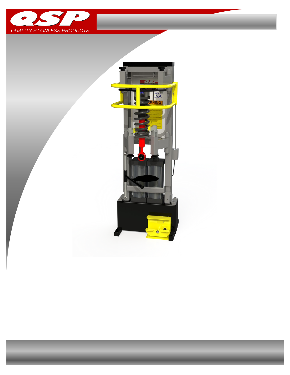
The SC-4000
features a safety valve that
prevents operation if the safety cag
e is not
lowered.
Never allow untrained or unauthorized
personnel to operate strut compressor.
Fully train all employees on
the proper use
and care of your strut compressor.
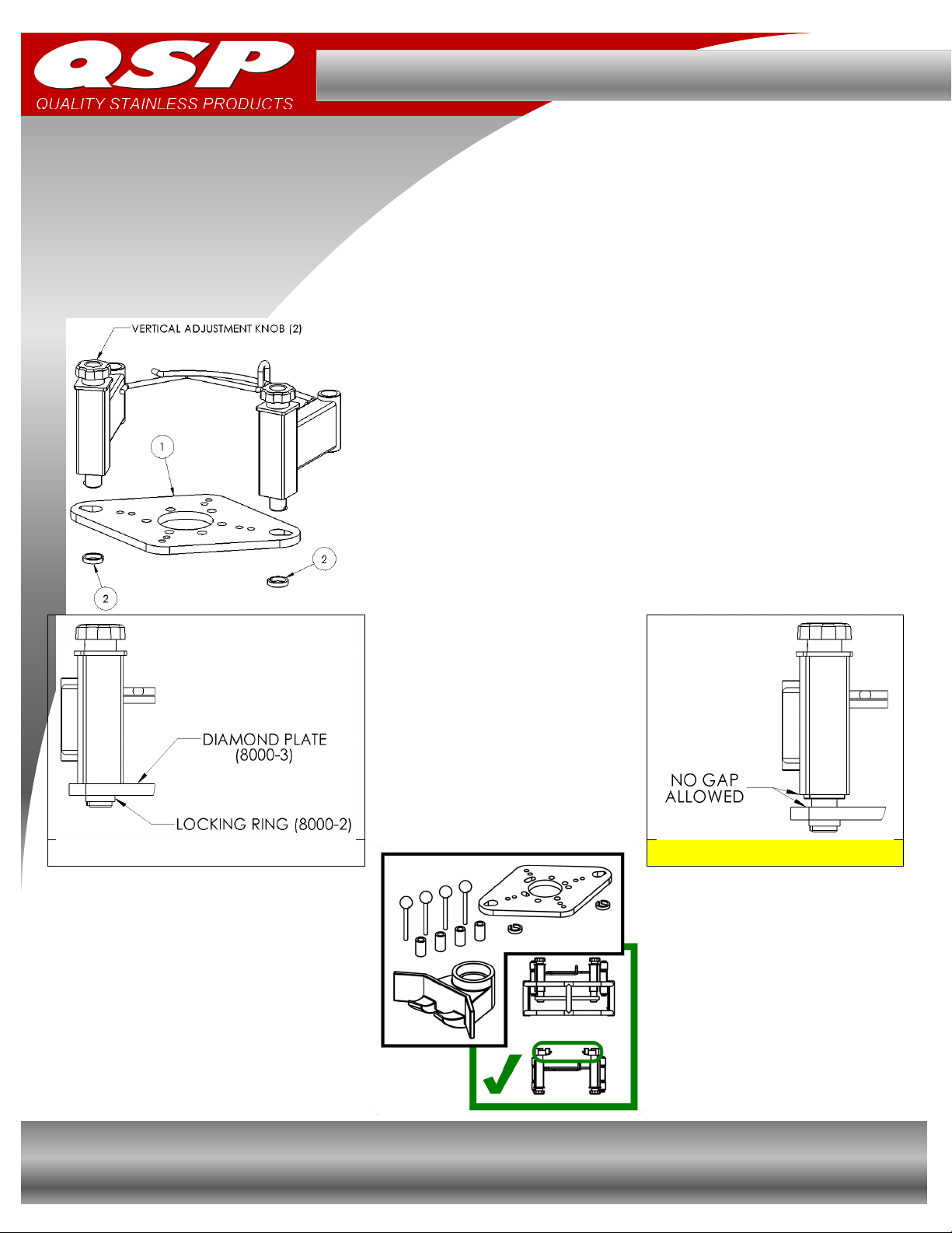
*If using a Diamond Plate kit, skip to page 9. *
One single finger hook and one double finger
hook should be used at the top of the unit and
also at the bottom.
MAINTENANCE INSTRUCTIONS
To avoid personal injury and damage to strut compressor, permit only qualified personnel to perform
maintenance on strut compressor(s). If you are not completely familiar with general automotive equipment
maintenance procedures, stop and contact manufacturer for instructions.
DAILY:
Inspect & repair or replace all loose bolts & damaged or broken components.
Inspect strut compressor clamp hooks for excessive wear or damage & replace as needed.
Inspect air system for leaks and basic function.
Inspect retention arms, knobs, foot pedals, and safety cage for damage and wear, replace as needed.
MONTHLY:
Inspect support tray & spring retention arm assemblies for damage, wear & tear, and dirt and debris in
mechanism. Clean, lubricate, repair & replace components as needed.
Lubricate cylinder rods with marine grade grease above seals, cycle unit twice to incorporate grease.
Clean strut compressor & inspect for rust.
EVERY 2YEARS:
Check all labels on strut compressor for legibility & make sure no labels are missing. Replace as
needed.

SC-4000 : Operating Instructions
4 Quality Stainless Products
OPERATING INSTRUCTIONS
Before operating your strut compressor, it is necessary to fully read and understand this instruction packet, &
the safety instructions. It is also recommended to dry run the strut compressor before compressing a spring to
become familiar with its operation and to help equalize air pressure in the system.
While avoiding any pinch points, follow instructions below to compress a spring:
***If using a Diamond Plate kit, skip to page 9***
1. Ensure supply air is connected.
2. Press the foot control pedal to actuate device
& equalize air pressure.
3. Lift safety cage & insert strut assembly into the
device. Put the low coil of the spring onto the
lower left clamp hook.
4.
Adjust lower right arm according to the
diameter of the spring & turn the adjustment
knob until
the hook has engaged the coil and
the strut assembly is straight up & down.
5.
Adjust the upper hooks so that they capture
the spring coils at the highest point. This
allows for maximum compression.
6.
Rotate handle of support plate
counterclockwise
ensuring that it can move
freely. Lift the support plate and rotate it
directly beneath the strut assembly and rotate
handle clockwise to lock support plate in
place.
7. Lower safety cage.
8. While holding the uppe
r arms of the unit in
place to support the strut assembly, press the
foot control pedal & SLOWLY
compress the
spring until solid contact is made on all hooks.
9. REMOVE HANDS from working area inside
the safety cage.
10. While standing beside the unit, remove any
fasteners from the strut/shock in the assembly.
This will allow the strut/shock to rest on the
support plate.
11.
While supporting the strut/shock, unlock the
support plate and move it to the side.
12. Remove old strut/shock and replace with new
unit & replace fasteners.
13.
Press the foot control pedal to decompress
spring and verify that all of the strut assembly
components are in the correct orientation and
position.
14. Lift the safety cage, disengage spring hooks,
and remove strut assembly.
!! WARNING !!
DO NOT disable or override the built in safety
measures. Serious injury, property damage,
or death may result.

www.QSPONLINE.com 5
OPERATING INSTRUCTIONS (continued…)
***If using a Diamond Plate kit, skip to page 9***
The strut compressor ships with 2 single claw hooks & 2 double claw hooks that can be used in any position.
When using all 4 hooks, the single claw hooks should be positioned according to the diagram below:
!! WARNING !!
INCORRECT claw positioning may result in equipment breakage,
property damage, and / or injury.
Proper placement of claw hooks is imperative to keep a spring or strut assembly in the
proper position while compressing. Claws should be in opposite positions top and
bottom. Single claw hooks should never be used together on the top or bottom of the
unit.
Please scan the QR barcode for further instruction & videos on how to setup your
equipment:

SC-4000 : Operating Instructions
6 Quality Stainless Products
Correct hook engagement on spring coil.
Incorrect engagement.
!! CAUTION !!
DO NOT position any body part directly above or below spring
assembly to be compressed!
Wear gloves and eye protection while operating unit!
TROUBLESHOOTING
SYMPTOM PROBLEM FIX
Arms do not move when foot
pedal is pressed.
1. Leak in air cylinder
Replace cylinder
2. Water in cylinder
Drain & repair cylinder, replace if needed
3. Restricted or kinked air line
Locate & correct restriction
Cylinder starts, but stalls
4. Leak in air line
Locate & repair leak
while in motion.
5. Insufficient air supply
Correct supply (150psi max, 20-30cfm)
Arms move but stop before
compressing spring.
1. Safety cage not in position
Ensure cage is all the way down
2. Foot valve failure
Inspect foot valve & repair/replace if needed
3. Insufficient air pressure
4. Improper setup
Increase pressure, DO NOT exceed 150psi
Straighten strut assembly
Ensure clamps are place as far apart as
possible
Arms drift instead of holding
position.
1. Air-line leakage
Find and repair line leak
2. Cylinder leakage
Perform service on cylinder
Repair/replace seals
Not able to engage clamps
on spring
1. Spring doesn’t have enough
coils
2. Spring length is too short
Remove upper clamps and replace with
Diamond plate adapter (PN: DP-4000)

www.QSPONLINE.com 7
REPLACEMENT PART DIAGRAM & PART NUMBER GUIDE
#
PART NUMBER
DESCRIPTION
QTY
#
PART NUMBER
DESCRIPTION
QTY
1
8000-7
TWO FINGER CLAMP
2
10
F-1/4 X 1/4NPT L
1/4 TUBE X 1/4 NPT ELBOW
1
2
8000-13
SINGLE FINGER CLAMP
2
11
T-.156X16 K-NYL TUBE
5/32 OD NYLON TUBE – BLK
3FT
3
DB-8000-070
ADJUSTING KNOB
4
12
T-.250 PU BLACK TUBE
1/4 PLASTIC AIR LINE – BLK
3FT
4
DB-7000-359
FOOT VALVE ASSEMBLY
1
13
5779K32
5/32 UNION TEE
3
5
1030
QUICK DISCON. 1/4 NPT
1
14
8000-3
DIAMOND PLATE
1
6
108-60
CHECK VALVE 1/4 NPT
1
15
8000-2
LOCKING RING
2
7
1345
1/4 NPT – 3/4-16 THD
1
16
8000-30
DIAMOND PLATE STUD SPACER
4
8
1347
BRASS T – 3X 1/4 NPT
1
17
8000-23
PLACEMENT PIN WITH KNOB
4
9
5779K147
5/32 PUSH X 1/4 NPT ELBOW
5

SC-4000 : Operating Instructions
8 Quality Stainless Products
PNEUMATIC SCHEMATIC
STRUT ASSEMBLY LIMITATIONS
The following parameters outline the most common spring dimensions that the strut compressor will accept.
CYLINDER STROKE (spring compression)………………………………………………….……9 7/8”
FINGER STROKE (clamp adjustment with knob)………………………………………….……..2 5/8”
MAXIMUM DISTANCE BETWEEN UPPER & LOWER CLAMPS……………………….……12 1/2"
MAXIMUM SPRING DIAMETER……………………………………………………………..…Ø11 1/2"
MINIMUM SPRING DIAMETER…………………………………………………………….……Ø3 1/2"
MAXIMUM COIL DIAMETER (spring wire)……………………………………………………...Ø1 1/2"
MINIMUM DISTANCE BETWEEN SPRING COILS………………………………………………..7/8”

www.QSPONLINE.com 9
INSTALLATION & USE OF DIAMOND PLATE KIT
The optional diamond plate kit (PN: DP-4000) is used on heavy duty springs, or where the assembly is not able
to be properly installed into the unit using the upper and lower claw hooks.
WHILE HOLDING THE DIAMOND PLATE (ITEM #1)
IN PLACE, ALIGN OPENING IN ITEM #2 WITH
BOSS ON THE SHAFT OF THE VERTICAL
ADJUSTMENT ARM. LIFT ITEM #2 INTO PLACE
BELOW THE DIAMOND PLATE THEN ROTATE
180° SO THAT THE OPENING NO LONGER
ALIGNS WITH BOSS.
AFTER INSTALLING
BOTH LOCKING RINGS,
ENSURE THAT THE
DIAMOND PLATE IS
DRAWN TIGHTLY TO
THE VERTICAL
ADJUSTMENT ARMS
WITH NO GAPS
CORRECT
INCORRECT
Continued on next page...

SC-4000 : Operating Instructions
10 Quality Stainless Products
INSTALLATION & USE OF DIAMOND PLATE KIT (continued…)
The optional diamond plate kit (PN: DP-4000) is used on heavy duty springs, or where the assembly is not able
to be properly installed into the unit using the upper and lower claw hooks.
Double check that the diamond plate is drawn
tight to the upper arms using the vertical
adjustment knobs.
Install a double claw hook on each of the lower
two arms.
Position the strut assembly onto the lower arms
using the vertical adjustment knobs to orient the
strut assembly in a vertical position.
If the strut assembly has studs that do not align
with a pattern in the diamond plate, install the
diamond plate stud spacers over the studs on the
strut assembly.
Slowly raise the strut into position with the
compressor and once the top end (or stud
spacers) contacts the diamond plate, verify that
both lower double claw hooks are contacting the
spring.
Install (4) custom placement pins to secure the
top end of the assembly & prevent it from moving
under compression.
Compress the strut assembly.
Position the strut support weldment (third hand)
under the assembly to hold it in place.
Remove the fastener from the top of the unit and
lower the strut compressor relieving the spring.
Reverse steps to reassemble.

www.QSPONLINE.com 11
WARRANTY INFORMATION
Your SC-4000 Strut Compressor has been thoroughly tested and is guaranteed for a period of 18 months from
the date of delivery. Under the terms of this guarantee, all components which are proven to be defective within
the warranty period will be repaired or replaced free of charge. Our technical service assistance is the sole
authority in determining whether or not defects come under the coverage of the guarantee. The guarantee
excludes all responsibility on the part of Quality Stainless Products (QSP) for direct or indirect loss or damage
to persons or things deriving from incorrect operation or servicing of this product. This guarantee is limited to
defects in materials, workmanship and assembly, and excludes all components subject to normal wear.
Furthermore, the guarantee excludes return shipping of defective part(s) to QSP. QSP will however ship the
replacement part by standard ground service at no charge.
QSP will not assume liability for damages caused by improper use of the strut compressor, including using the
device for something other than its intended use.
Parts Department 888-473-5378
TYPE: Strut Compressor
MODEL: SC-4000
Serial Number:
______________________________________
Please retain this document for reference when calling Technical Assistance.
NOTES:

SC-4000 : Operating Instructions
12 Quality Stainless Products
11515 Adie Road
Maryland Heights, MO 63043
888-473-5378
HTTP://WWW.QSPONLINE.COM
Table of contents
Other QSP Service Equipment manuals