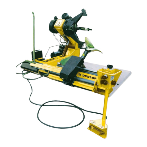
QSP LM-350 User manual

Phone (888) 473-5378
Local Phone (314) 699-9613
11515 Adie Rd. Maryland Heights, MO 63043
Fax: (314) 699-9617
Website: www.qsponline.com
_____________________________________________________________________________
LM-350 Warranty
The LM-350 has been thoroughly tested and is guaranteed for a period of 12 months from the date of
delivery. Under the terms of this guarantee all components which are proven defective within the
warranty period will be repaired or replaced free of charge. Our technical assistance service is the
sole authority in determining whether or not defects come under the coverage of the guarantee. The
guarantee excludes all responsibility on the part of the Quality Stainless Products for direct or
indirect loss or damage to persons or things deriving from incorrect operation or servicing of the
product. The guarantee is limited to defects in materials, workmanship and assembly, and excludes
all components subject to normal wear. Furthermore, the guarantee excludes return shipping of
defective part to QSP. We will however ship the replacement part by standard ground service at no
charge.
Parts Department 888-473-5378
TYPE: Tire and Wheel lift
MODEL: LM-350
_________________________________________________________________________________
OPERATION INSTRUCTIONS
Removing the Tire and Wheel Assembly from a vehicle using The LM-350
1. Attach air to LM-350
2. Position LM-350 under tire and wheel on the vehicle and raise roller carriage by operating
the raise/lower control. (Valve is variable speed. The more you move the toggle control in the
upward or downward direction the faster the carriage will move)
3. Once the rollers have made contact with the bottom of the tire, slowly release the toggle
valve.
4. Pull the top of the tire toward you and disengage wheel from the vehicle.
5. With the tire on the rollers back the lift away from the vehicle and lower.
6. Remove the tire and wheel assembly from the LM-350
Installing the Tire and Wheel Assembly on a vehicle using the LM-350
1. Position the tire and wheel assembly on the LM-350 rollers
2. Raise the tire to close to spindle height.
3. Rotate the tire and wheel to align lug studs to the wheel.
4. Slowly raise or lower to exact position and push the top of the tire and wheel assembly
forward to engage the stud and lug nut holes.
5. Install lug nuts and lower tire and wheel lift.

61 3
8
"
1559.7mm
21 3
4
"
552.8mm
40"
1016mm
38 3
16
"
970.2mm
37 11
16
"
957.6mm
LIFTING CAPACITY: 350LBS
LM-350 INSTALLATION &
ASSEMBLY INSTRUCTION
THE INFORMATION CONTAINED IN THIS
DRAWING IS THE SOLE PROPERTY OF
QSP. ANY REPRODUCTION IN PART OR AS
A WHOLE WITHOUT THE WRITTEN
PERMISSION OF QSP IS PROHIBITED.
PROPRIETARY AND CONFIDENTIAL
2

ITEM NO.
PART NUMBER
DESCRIPTION
1
LM-200-172
CONTROL BOX COVER
1
2
LM-200-415
ROLLER SUPPORT
1
3
LM-200-901
AIR VALVE
1
4
LM-200-930
CASTER 5" DIA WHEEL
2
5
LM-200-931
CASTER 3" DIA WHEEL
2
6
LM-200-R-152
ROLLER
1
7
LM-350-10
LM-350 DECAL KIT
1
8
LM-350-100
HD Cylinder 100 B- 500 S
1
9
LM-350-112
COLUMN WELDED ASSY
1
10
LM-350-117
TROLLEY WELDMENT
1
11
LM-350-119
SPACER
3
12
LM-350-120
SUPPORT PLATE
1
13
LM-350-122
FORK WELDMENT
1
14
LM-350-131
ROLLER
4
15
LM-350-136
PULLEY WELDMENT LM-350
1
16
LM-350-137
ROLLER
2
17
LM-350-140
ROLLER PIN
1
18
LM-350-141
CABLE RETAINER
2
19
LM-350-142
PULLEY PIN
2
20
LM-350-144
COVER LH
1
21
LM-350-145
COVER LH
1
22
LM-350-146
COVER REAR
1
23
LM-350-147
TOOL TRAY
1
24
LM-350-148
ROLLER-TROLLEY
6
25
LM-350-149
CHANNEL ASSY
1
26
LM-350-714
CASTER SUPPORT RH
1
27
LM-350-715
CASTER SUPPORT LH
1
28
LM-500-301
PULLEY 5" OD X 1/2" W
1
29
LM-500-705
LM-500 CABLE ASSEMBLY
1
30 1030
QUICK DISCONNECT 1/4 NPT
1
31
108-60
CHECK VALVE 1/4 NPT
1
32 1345
1/4 NPT-3/4-16 THD
1
33 1347
AIR LINE TEE 1/4 NPT
1
34
137-71
YELLOW COIL HOSE 4 1/2 COIL
1
35
8000-8
GRIP
2
36
F-1/2NPT X 3/8T L
1/2 NPT X 3/8 TUBE ELBOW
2
37
F-1/4 X 1/4NPT L
.25 TUBE X .25NPT ELBOW
1
38
F-1/4NPTX3/8T FCL
FLOW CONTROL ELL 3/8 NPT
2
39
H-LM-350 HW
LM-350 HARDWARE KIT
1
40
T-1/4 PU TUBE-FLEX
1/4 BLACK POLYURETHANE AIR LINE
0.75
41
T-3/8 PU BLACK TUBE
3/8 PLACK POLYURETHANE TUBE
6
LM-350 INSTALLATION &
ASSEMBLY INSTRUCTION
THE INFORMATION CONTAINED IN THIS
DRAWING IS THE SOLE PROPERTY OF
QSP. ANY REPRODUCTION IN PART OR AS
A WHOLE WITHOUT THE WRITTEN
PERMISSION OF QSP IS PROHIBITED.
PROPRIETARY AND CONFIDENTIAL
3

C
D
232215
21 35 9
8
35
20
1012
25
26
4
27
4
5
5
213
16
6
16
DETAIL C
SCALE 1 : 12
30
32
31
33
37
338
1
38
DETAIL D
SCALE 1 : 9
18
CABLE ASSEMBLY
LM-200-927
NOT DEPICTED
ON PRINT
LM-350 INSTALLATION &
ASSEMBLY INSTRUCTION
THE INFORMATION CONTAINED IN THIS
DRAWING IS THE SOLE PROPERTY OF
QSP. ANY REPRODUCTION IN PART OR AS
A WHOLE WITHOUT THE WRITTEN
PERMISSION OF QSP IS PROHIBITED.
PROPRIETARY AND CONFIDENTIAL
4

ATTACH THE MAST TO THE
1.
MAST SUPPORT USING HARDWARE NOTED.
3/8"-16 X 1-1/4" LG
BOLT, WASHER, NYLOCK
NUT. 4 PLACES.
M10 SOCKET
HD CAP SCREWS
2 PLACES
LEFT HAND
CASTER SUPPORT
SHOWN
MAST SUPPORT
AIR CYLINDER
ATTACH CASTER SUPPORTS RH & LH
1.
TO MAST SUPPORT USING HARDWARE NOTED.
CASTER SUPPORT
LH SHOWN.
3/8"-16 X 1-1/4" LG BOLTS
WASHER, AND NYLOCK NUTS.
MAST SUPPORT
STEP #2 MAST INSTALLATION
STEP #1 CASTER INSTALLATION.
LM-350 INSTALLATION &
ASSEMBLY INSTRUCTION
THE INFORMATION CONTAINED IN THIS
DRAWING IS THE SOLE PROPERTY OF
QSP. ANY REPRODUCTION IN PART OR AS
A WHOLE WITHOUT THE WRITTEN
PERMISSION OF QSP IS PROHIBITED.
PROPRIETARY AND CONFIDENTIAL
5

ROLLER
ROLLER SUPPORT
3/8-16 X 7/8" LG
BOLT, WASHER
LOCK WASHER
2 PLACES
WHEEL FORK
ASSEMBLY
3/8-16 X 3/4" LG
BOLT, WASHER
LOCK WASHER
2 PLACES
REAR COVER
RH COVER
TOOL TRAY
1/4-20 X 5/8" LG
BOLT, WASHER
4 PLACES
CONTROL BOX
STEP #4 TOOL TRAY INSTALLATION.
STEP #3 FORK INSTALLATION.
ATTACH WHEEL FORK ASSEMBLY
WITH HARDWARE NOTED. IMPROPER
LOCATION OF HARDWARE CAN CAUSE
INTERFERENCE OF BOLT WITH MAST.
LM-350 INSTALLATION &
ASSEMBLY INSTRUCTION
THE INFORMATION CONTAINED IN THIS
DRAWING IS THE SOLE PROPERTY OF
QSP. ANY REPRODUCTION IN PART OR AS
A WHOLE WITHOUT THE WRITTEN
PERMISSION OF QSP IS PROHIBITED.
PROPRIETARY AND CONFIDENTIAL
6

AIR CONTROL BOX
AIR VALVE TOGGLE
CONTROL
SHOP AIR
CONNECTION
REAR COVER
COIL HOSE FOR
PNEUMATIC TOOL
(NOT SHOWN)
FLOW CONTROL
VALVE
2 PLACES
STEP #5 AIR LINE CONNECTION
NOTE:
THE FLOW CONTROL VALVES GOVERN THE RATE AT WHICH
THE WHEEL FORK RAISES AND LOWERS. THESE CONTROLS
ARE PRESET AT THE FACTORY, BUT CAN BE ADJUSTED BY THE END
USER IF THE DESIRED SPEED NEEDS TO BE INCREASED OR DECREASED.
SUGGESTED MAINTENANCE:
THE LM-350 LIFT OPERATES BEST WITH SHOP AIR THAT IS CLEAN AND DRY.
1.
PERIODICALLY CHECK THE TIGHTNESS OF ALL FASTENERS.
2.
PERIODICALLY CHECK THE CONDITION OF LIFTING CABLE. IF ANY FRAYED STRANDS
3.
ARE NOTICED REPLACE CABLE.
LM-350 INSTALLATION &
ASSEMBLY INSTRUCTION
THE INFORMATION CONTAINED IN THIS
DRAWING IS THE SOLE PROPERTY OF
QSP. ANY REPRODUCTION IN PART OR AS
A WHOLE WITHOUT THE WRITTEN
PERMISSION OF QSP IS PROHIBITED.
PROPRIETARY AND CONFIDENTIAL
7
Table of contents
Other QSP Tyre Changer manuals
Popular Tyre Changer manuals by other brands

Ranger Products
Ranger Products R23 Installation and operation manual

Ranger Products
Ranger Products R715 Installation and operation manual

HPA-Faip
HPA-Faip M 824 LL Operator's manual

Fasep
Fasep TOP AUTOMATIC 4.0 Operating and maintenance manual

SICE
SICE S 58 LL instruction manual

Katool
Katool KT-810 Installation, Operation and Maintenance User’s Manual