Quantum Rehab Synergy Assembly instructions

SynergyTRU-Balance
PowerTilt
BASICOPERATIONINSTRUCTIONS
SynergySeat
TM

Synergy Seat www.pridemobility.com
2 Basic Operation Instructions
WARNING! A Quantum Rehab Provider or a qualified
technician must perform the initial setup of this product
and must perform all of the instructions in this manual.
The symbols below are used throughout this owner’s manual and on the
power chair to identify warnings and important information. It is very
important for you to read them and understand them completely.
WARNING! Indicates a potentially hazardous condition/
situation. Failure to follow designated procedures can
cause either personal injury, component damage, or
malfunction. On the product, this icon is represented as a
black symbol on a yellow triangle with a black border.
MANDATORY! These actions should be performed as
specified. Failure to perform mandatory actions can cause
personal injury and/or equipment damage. On the product,
this icon is represented as a white symbol on a blue dot
with a white border.
PROHIBITED! These actions are prohibited. These actions
should not be performed at any time or in any
circumstances. Performing a prohibited action can cause
personal injury and/or equipment damage. On the product,
this icon is represented as a black symbol with a red circle
and a red slash.
NOTE: These instructions are compiled from the latest specifications and
product information available at the time of publication. We reserve the
right to make changes as they become necessary. Any changes to our
products may cause slight variations between the illustrations and
explanations in this manual and the product you have purchased. The
latest/current version of this manual is available on our website.
NOTE: This product is compliant with WEEE, RoHS, and REACH
directives and requirements.
NOTE: This product meets IPX4 classification (IEC 60529).
NOTE: The product and its components are not made with natural rubber
latex. Consult with the manufacturer regarding any after-market
accessories.
SAFETY GUIDELINES
Copyright © 2014
Pride Mobility Products
INFMANU2015/Rev N/October 2014

www.pridemobility.com Synergy Seat
Basic Operation Instructions 3
LABEL INFORMATION...................................................................4
INTRODUCTION..............................................................................5
THE SYNERGY SEAT.....................................................................6
PRECAUTIONARY GUIDELINES...................................................8
SEAT REMOVAL/INSTALLATION...............................................11
TOGGLE OPERATION..................................................................15
ARMREST OPTIONS....................................................................21
Cantilever..................................................................................22
Flip-Up......................................................................................24
Heavy Duty Drop-In..................................................................26
Single Post Quick Height Adjustable Drop-In...........................28
Two Post Height Adjustable Flip-Up.........................................31
CONTROLLER POSITION............................................................32
POWER SEAT ELEVATOR OPTION............................................34
MANUAL RECLINE OPTION........................................................35
SYNERGY MANUAL TILT OPTION..............................................36
CARE AND MAINTENANCE.........................................................37
WARRANTY..................................................................................38
TABLE OF CONTENTS

4 Basic Operation Instructions
Synergy Seat www.pridemobility.com
Indicates that this product conforms to the ANSI/RESNA
WC/Vol. 4, Section 19/ISO 7176-19 standards for transport
of an occupied power chair in a motor vehicle. If this label
is not found on this power chair or on the seating system,
this indicates that this product is not approved for use as a
seat in a motor vehicle. In this case, the power chair
occupant must transfer into one of the motor vehicle seats
equipped with approved safety belt.
Indicates power chair securement points.
Consult your Quantum Rehab Provider
before making any changes to your
seating system configuration.
PRODUCT SAFETY SYMBOLS
The symbols below are used on the seating system to identify warnings,
mandatory actions, and prohibited actions. It is very important for you to
read and understand them completely.
LABEL INFORMATION
Read and follow the information in the owner’s manual.
Avoid exposure to rain, snow, ice, salt, or standing water
whenever possible. Maintain and store in a clean and dry
condition.
EMI/RFI—This product has been tested and passed at an
immunity level of 20 V/m.
Use correct tie-down points for controller harness to
prevent the harness from getting caught in the drive tires
or pinched in the seat frame.
Maximum seating weight.
Crush/pinch point.

www.pridemobility.com Synergy Seat
Basic Operation Instructions 5
INTRODUCTION
WELCOME to Quantum Rehab, a division of Pride Mobility Products
(Pride). The product you have purchased combines state-of-the-art compo-
nents with safety, comfort, and styling in mind. We are confident that the
design features will provide you with the conveniences you expect during
your daily activities. Understanding how to safely operate and care for this
product should bring you years of trouble free operations and service.
Read and follow all instructions, warnings, and notes in this manual before
attempting to operate your product for the first time. You must also read all
instructions, warnings, and notes contained in any supplemental instruc-
tional booklets for the controller, front riggings, and/or seating system that
accompanied your mobility product before initial operation. Your safety
depends upon you, as well as your provider, caretaker, or healthcare profes-
sional in using good judgement.
This manual is to be used in addition to the power base owner’s manual that
came with your power chair. If there is any information in this manual which
you do not understand, or if you require additional assistance for setup or
operation, please contact your Quantum Rehab Provider. Failure to follow
the instructions, warnings, and notes in this manual and those located
on your Pride product can result in personal injury and/or product
damage and will void Pride’s product warranty.
PURCHASER’S AGREEMENT
By accepting delivery of this product, you promise that you will not change,
alter, or modify this product or remove or render unusable or unsafe any
guards, shields, or other safety features of this product; fail, refuse, or
neglect to install any retrofit kits from time to time provided by Pride to
enhance or preserve the safe use of this product.
NOTE: If you ever lose or misplace your copy of this manual, contact us
and we will be glad to send you a new one immediately.

6 Basic Operation Instructions
Synergy Seat www.pridemobility.com
THE SYNERGY SEAT
The Synergy Seat is a unique seating system designed specifically for the
Pride Power Chair. It is fully adjustable to meet the individual needs of the
user, and it is mounted to a Pride power base to provide maximum
maneuverability.
Reusable hook and loop fasteners are included in your owner’s package for
use in attaching the seat cushion to the seat base. These fasteners are not
intended for use on cushions with anti-skid material, as they may damage
the seat cushion.
Figure 1 provides information on the Synergy Seat components. Use this
diagram to familiarize yourself with the function and location of each
component before using the Synergy Seat.

Basic Operation Instructions 7
www.pridemobility.com Synergy Seat
Figure 1. Synergy Seat and Options
MANUAL RECLINE
BACK (OPTIONAL)
With this option, the
seatback can be adjusted
to recline to an angle
between 90 and 180
4-WAY TOGGLE CONTROLS (OPTIONAL)
Allow the user to control the seat elevator and
articulating leg rest actuators (if so equipped).
4-way
Button
Toggle
4-way
Toggle
Quad
Push-Button
Control
ATTENDANT
CONTROL MODULE
(OPTIONAL)
Allows an attendant to
control the actuators. Any
action made through
the Attendant Control
Module overrides the
toggle actions made by
the user.
ARMRESTS
Available in five
basic styles:
Heavy Duty Drop-in
Flip-up
(standard)
Cantilever
Single Post Quick
Height Adjustable
Drop-in
(available in adult
and pediatric sizes)
Two Post Height
Adjustable Flip-up
POWER ARTICULATING
LEG RESTS (ALR)
Maintain correct
knee-to-heel measurements
when user's legs are raised
or lowered.
SWING-AWAY POWER
ARTICULATING
LEG RESTS (ALR)
Maintain correct
knee-to-heel measurements
when user's legs are raised
or lowered.
POWER ARTICULATING
FOOT PLATFORM (AFP)
Maintains correct
knee-to-heel measurements
when user's legs are raised
or lowered.
HIGH PIVOT POWER
ELEVATING
LEG RESTS (ELR)
Mimic the motion of the
knee during leg elevation.
LEG RESTS (OPTIONAL)
MANUAL TILT
(OPTIONAL)
With this option, the
seatback can be adjusted
to tilt to an angle between
0 and 45

8 Basic Operation Instructions
Synergy Seat www.pridemobility.com
PRECAUTIONARY GUIDELINES
Before using the Synergy Seat, please read the following. These guidelines
are provided for your benefit and will aid you in the safe operation of the
seating system.
Turn off the power before you are seated in the Synergy Seat.
Always have assistance when you are being seated in the Synergy Seat.
Follow all of the procedures and heed the warnings as explained in your
power chair owner’s manual.
WARNING! The center of gravity of your seating system
was factory set to a position that meets the needs of the
demographic majority of users. Your Quantum Rehab
Provider has evaluated your seating system and made any
necessary adjustments to suit your specific requirements.
Do not change your seating configuration without first
contacting Pride Mobility Products or your Quantum Rehab
Provider.
WARNING! Should the fittings on your Synergy Seating
System become loose, report the problem immediately to
your Quantum Rehab Provider.
WARNING! Your Synergy Seating System is not approved
for use as a seat in any vehicle. Use the seats and occupant
restraints provided by the manufacturer of the vehicle.
WARNING! Extreme temperatures can affect the
temperature of your seating system components and may
cause skin irritation. Use caution when your power chair
has been used or stored in an extremely hot or cold
environment.
MANDATORY! Do not exceed the weight capacity listed in
your power chair manual or 300 lbs. (136 kg), whichever is
less. If equipped with a Synergy Seat HD, do not exceed the
weight capacity of the power chair or 650 lbs. (295 kg),
whichever is less.
WARNING! Possible pinch point hazard! Ensure all
ventilator wires and tubes are routed properly to avoid
component damage during seat adjustment and power
chair operation. Follow the wire routing instructions
provided by the manufacturer of the ventilator.
NOTE: The addition of an optional vent tray to your Synergy Seat may
change the overall weight, size, and/or center of gravity of your power
chair. Do not make any changes to your seating configuration without
contacting your Quantum Rehab Provider.

Basic Operation Instructions 9
www.pridemobility.com Synergy Seat
Motor Vehicle Transport
The Synergy Seat is not approved for use as a seat in a motor vehicle unless
the power base is equipped with a manufacturer-approved transit securement
system and the seat is labeled to show conformity to the standards of ANSI/
RESNA WC/Vol. 4, Section 19/ISO 7176-19. Pride recommends that the
power chair user transfer into the vehicle seat and use the vehicle-installed
restraint system if and whenever feasible. The power chair should then be
stored and secured in the vehicle. In addition, all removable power chair
parts, including the armrests, seat, front riggings, controller, and shrouds,
should be removed and properly secured during motor vehicle transport.
WARNING! The Synergy Seating System is not approved for
use as a seat in any vehicle unless it has been tested and
approved for occupied use according to ANSI/RESNA WC/
Vol. 4, Section 19/ISO 7176-19 standards. Use the seats
and occupant restraints provided by the manufacturer of
the vehicle. If your power chair is equipped with a
manufacturer-installed transit securement system, please
refer to the supplemental safety information provided with
your power chair.
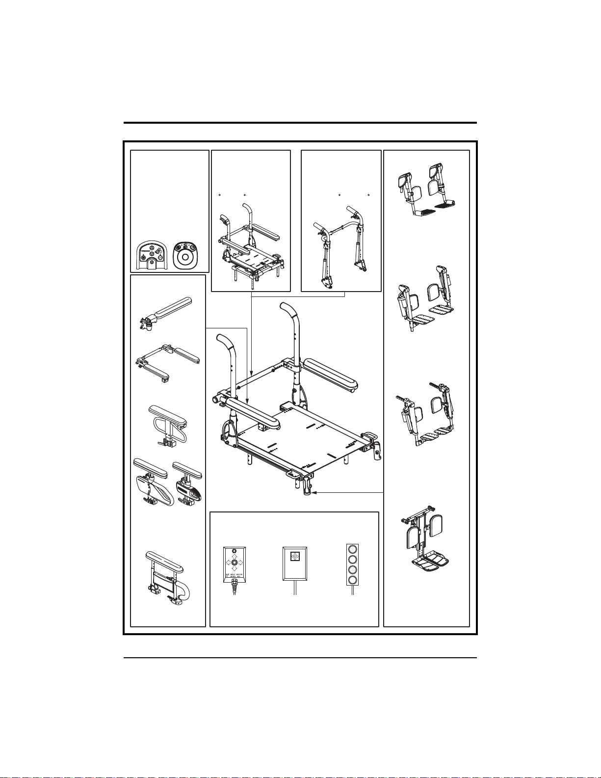
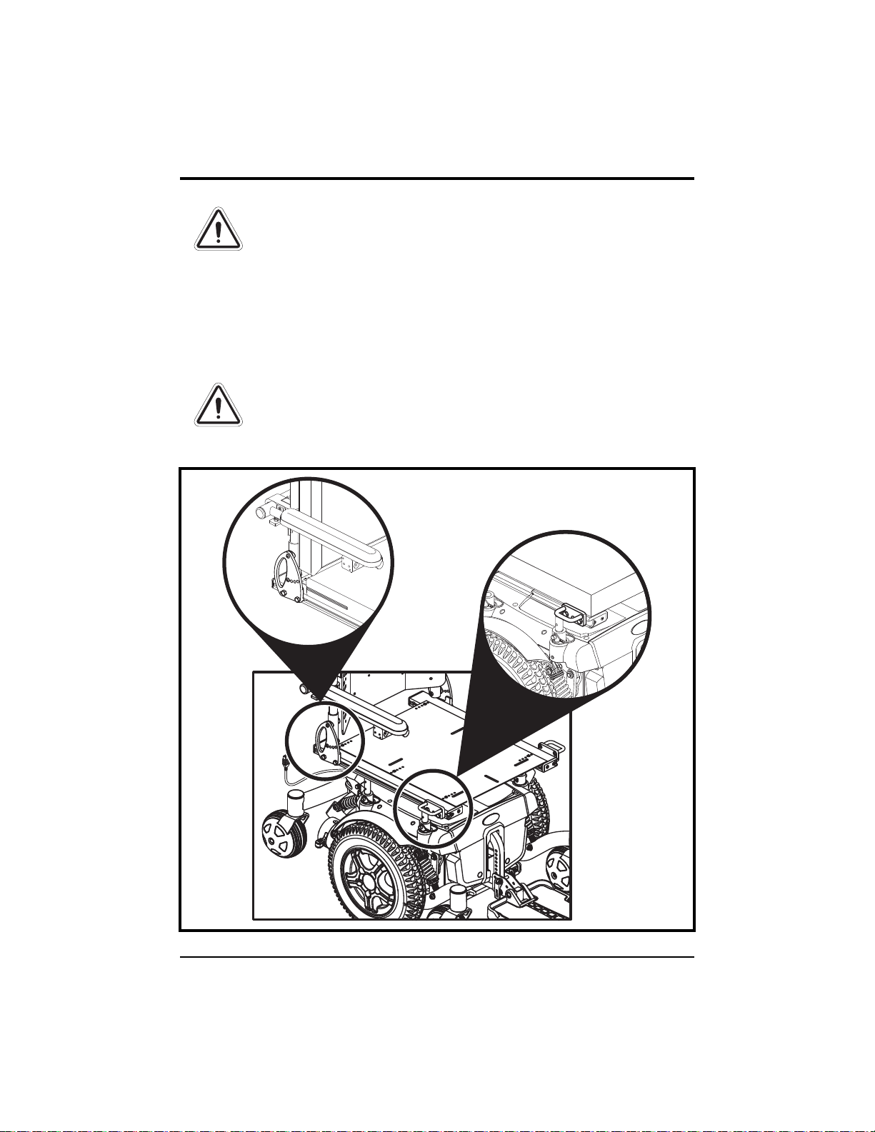
The steel brackets mounted to the front and rear of the Synergy Seating
System (see figure 2) can provide securement points when full disassembly
and stowage of the power chair is not feasible. These brackets should only
be used with an unoccupied power chair that is secured by an approved
securement system in accordance with the manufacturer’s instructions.
Pride makes no representation of suitability for use with specific securement
systems nor can we anticipate the various situations that might arise in use
of public transportation systems. For detailed instructions on the use of
securement systems, refer to the manufacturer of the system used.
WARNING! The Synergy securement brackets are for
unoccupied use only. The power chair occupant must
transfer into the vehicle seat and use the vehicle-installed
restraint system during motor vehicle transport.
When securing the power chair for unoccupied transport, adhere to the
following precautions:
Always ensure that the power chair motors are in drive mode (drive
engaged) and that the power chair controller is turned off.
Secure the power chair in a forward-facing position in the vehicle.
Attach tie-down straps (front and rear) only to the provided securement
points. Tighten the straps to sufficiently remove all slack.

10 Basic Operation Instructions
Synergy Seat www.pridemobility.com
Figure 2. Unoccupied Securement Brackets on a Synergy Seat
WARNING! Never attach tie-downs to adjustable, moving,
or removable parts of the power chair such as armrests,
front riggings, and wheels.
Position the anchor points for the rear tie-down straps directly behind
the rear securement points on the power chair. The front tie-down straps
should anchor to floor points that are spaced wider than the power chair
to provide increased lateral stability.
WARNING! Ensure unoccupied power chairs are properly
secured to the motor vehicle during transport. Power
chairs that are not properly secured can become a hazard
to vehicle passengers in the event of a crash, sudden
stopping, or swerving, as the power chair could tip or slide
out of place.

Basic Operation Instructions 11
www.pridemobility.com Synergy Seat
SEAT REMOVAL/INSTALLATION
The Synergy Seat can be disconnected from the power base to aid in transport
or storage.
WARNING! Removing and installing your seating system
should be accomplished with no fewer than two people.
To remove the Synergy Seat from the power base:
1. Remove the safety snap pins from all of the seat mount connectors. See
figure 3.
2. Lift the Synergy Seat. One person should lift from the front of the seat
and another should lift from the rear. Lift the seat straight up out of the
seat mount connectors.
To install the Synergy Seat on the power base:
1. Lift the Synergy Seat above the power base. One person should lift from
the front of the seat and another should lift from the rear.
2. Lower the seat so that the four seat towers are inserted into the four seat
mount connectors. See figure 3.
3. Without removing the seat towers from the seat mount connectors, lift
either the front or rear of the Synergy Seat and insert the safety snap pins
to lock the seat at the desired height.
4. If an angled seat is desired, set the front of the Synergy Seat higher than
the rear. The seat base angle can be adjusted to achieve up to 20° of
posterior tilt (seat dump).
NOTE: You may need to loosen the setscrews on the seat mount connec-
tors on some power chairs.
Figure 3. Seat Installation/Removal
POWER BASE
SAFETY
SNAP PIN
SEAT TOWER
SEAT MOUNT
CONNECTOR

12 Basic Operation Instructions
Synergy Seat www.pridemobility.com
To remove the Synergy Seat from the Q6 Edge power base:
1. Remove the screws from all of the seat interface weldments. See
figure 4.
2. Lift the Synergy Seat. One person should lift from the front of the seat
and another should lift from the rear. Lift the seat straight up out of the
seat interface weldments.
To install the Synergy Seat on the Q6 Edge power base:
1. Lift the Synergy Seat above the power base. One person should lift from
the front of the seat and another should lift from the rear.
2. Lower the seat so that the four seat mounting brackets are inserted into
the four seat interface weldments. See figure 4.
3. Without removing the seat mounting brackets from the seat interface
weldments, lift either the front or rear of the Synergy Seat and insert the
screws to lock the seat at the desired height.
4. If an angled seat is desired, set the front of the Synergy Seat higher than
the rear. The seat base angle can be adjusted to achieve up to 20° of
posterior tilt (seat dump).
Figure 4. Seat Installation/Removal on Q6 Edge
SCREWS
SEATMOUNTING
BRACKET
SEATINTERFACE
WELDMENT
POWERBASE
TRAPEZE BAR

Basic Operation Instructions 13
www.pridemobility.com Synergy Seat
Toremove theSynergy Seat from the Quantum/Jazzy 1450 power base:
1. Remove the screws from the four seat mounting brackets. See figure 5.
2. Lift the Synergy Seat. One person should lift from the front of the seat
and another should lift from the rear. Lift the seat straight up out of the
seat mounting brackets.
To install the Synergy Seat on the Quantum/Jazzy 1450 power base:
1. Lift the Synergy Seat above the power base. One person should lift from
the front of the seat and another should lift from the rear.
2. Lower the seat so that the rails rest on the four seat mounting brackets.
Install the screws through the seat mounting bracket and into the T-nuts
installed into the bottom of the Synergy Seat rail. See figure 5.
3. Seat height adjustments can be achieved by removing the height adjust-
ment screws. See figure 5. With the height adjustment screws removed,
lift either the front or rear of the Synergy Seat and insert the screws
through lock washers to set the seat at the desired height.
4. If an angled seat is desired, set the front of the Synergy Seat higher than
the rear. The seat base angle can be adjusted to achieve up to 12° of
posterior tilt (seat dump).
Figure 5. Seat Installation/Removal on Quantum/Jazzy 1450
POWERBASE
SEATMOUNTING
BRACKET
SCREWS
HEIGHT ADJUSTMENT
SCREWS LOCK
WASHERS

14 Basic Operation Instructions
Synergy Seat www.pridemobility.com
Flip-forward Back Canes
The flip-forward back canes allow the
user to flip the seatback forward for
easier transportation.
To flip the seatback forward:
1. Rotate the release lever on both
back canes toward the rear of the
seat to unlatch the back canes. See
figure 6.
2. Fold the seatback down.
To return the seatback to an upright
position:
1. Lift the seatback up and place in the
upright position.
2. Rotate the release lever on both
back canes toward the front of the
seat to latch the back canes. See fig-
ure 7. Ensure a red sticker on the
release lever is not visible.
WARNING! If a red
sticker is visible, the
release lever is not
fully latched. Ensure
both release levers are
fully latched before
sitting in your power
chair.
Figure 7. Flip-forward Back Canes
(Latched)
LATCHED
UNLATCHED
RED STICKER
Figure 6. Flip-forward Back Canes
(Unlatched)

Basic Operation Instructions 15
www.pridemobility.com Synergy Seat
Figure 9. 4-way Toggle Operation
Figure 8. 2-way Toggle Operation
NOTE: This manual will discuss toggle, joystick, and Attendant Control
Module operations only. If your Synergy Seating System is equipped with
a different operating device, please refer to the operation manual supplied
with that device and/or your power chair owner’s manual.
TOGGLE OPERATION
Your Synergy Seat may be equipped with either a 2-way toggle or one of
three available 4-way toggles.
NOTE: Your Synergy Seat may be equipped with any number of these
functions.
2-way Toggle
1. To elevate, pull the toggle switch
backward.
2. To return to the down position,
push the toggle switch forward.
4-way Toggle
Seat Elevator Function (Optional)
1. To elevate the seat, push the toggle
switch to the left.
2. To lower the seat, push the toggle
switch to the left, release, then push
to the left again.
Combined Leg Rest Function
(Optional)
1. To elevate both leg rests, push the
toggle switch to the right.
2. To lower both leg rests, push the
toggle switch to the right, release,
then push to the right again.

16 Basic Operation Instructions
Synergy Seat www.pridemobility.com
Independent Leg Rest Function (Optional)
1. To elevate the left leg rest, push the toggle switch to the left.
2. To lower the left leg rest, push the toggle switch to the left, release, then
push to the left again.
3 To elevate the right leg rest, push the toggle switch to the right.
4 To lower the right leg rest, push the toggle switch to the right, release,
then push to the right again.
NOTE: The power elevator option is not available when the independent
leg rest option is selected.
4-way Button Toggle
Seat Elevator Function (Optional)
1. To elevate the seat, push the toggle
button to the left.
2. To lower the seat, push the toggle
button to the left, release, then push
to the left again.
Combined Leg Rest Function
(Optional)
1. To elevate both leg rests, push the
toggle button to the right.
2. To lower both leg rests, push the
toggle button to the right, release,
then push to the right again.
Figure 10. 4-way Button Toggle
Operation
Independent Leg Rest Function (Optional)
1. To elevate the left leg rest, push the toggle button to the left.
2. To lower the left leg rest, push the toggle button to the left, release, then
push to the left again.
3. To elevate the right leg rest, push the toggle button to the right.
4. To lower the right leg rest, push the toggle button to the right, release,
then push to the right again.
NOTE: The power elevator option is not available when the independent
leg rest option is selected.

Basic Operation Instructions 17
www.pridemobility.com Synergy Seat
Quad Push-Button Control Toggle
Seat Elevator Function (Optional)
1. To elevate the seat, push the third button.
2. To lower the seat, push the third button
again.
Combined Leg Rest Function (Optional)
1. To elevate both leg rests, push the fourth
button.
2. To lower both leg rests, push the fourth
button again.
Independent Leg Rest Function (Optional)
Figure 11. Quad Push-
Button Control Toggle
Operation
1
2
3
4
1. To elevate the left leg rest, push the third button.
2. To lower the left leg rest, push the third button again.
3. To elevate the right leg rest, push the fourth button.
4. To lower the right leg rest, push the fourth button again.
NOTE: The power elevator option is not available when the independent
leg rest option is selected.
Q-Logic Joystick Operation
1. Push the On/Off and Mode Select Lever up once to power on the chair
and the controller.
2. Push the On/Off and Mode Select Lever up several times until the seat
screen is displayed on the LCD or push the key II select button once to
go directly to actuator mode.
3. Push the joystick to the left or right to cycle through the available actu-
ators until the desired actuators are illuminated on the actuator indicator.
See figure 12.
4. When the desired actuator is selected, give a forward command to the
joystick to adjust position in one direction or give a reverse command to
the joystick to adjust position in the opposite direction.
5. Push and release the On/Off and Mode Select Lever until you return to
the desired drive profile.

18 Basic Operation Instructions
Synergy Seat www.pridemobility.com
AFP/Dual ALR/
Dual ELR Mode
Elevating Seat Mode ALR/ELR Mode (right) ALR/ELR Mode (left)
Figure 12. Actuator Mode (Q-Logic)
Figure 13. Q-Logic Attendant Control Module
NOTE: Your Synergy Seat may be equipped with some or all of these
functions.
Q-Logic Attendant Control Module
To adjust any of the actuators, press the mode key until you reach your seat-
ing profile and then push the joystick to the right to cycle until the desired
actuator is illuminated on the actuator indicator (see figure 13). Move the
joystick forward or backward to activate the desired actuator.
ACTUATOR INDICATOR
(RECLINE)
(TILT)
(LEFT LEG)
(RIGHT LEG)
(ELEVATE)
MODE KEY
JOYSTICK
POWER KEY

Basic Operation Instructions 19
www.pridemobility.com Synergy Seat
Seat Elevator Function (Optional)
1. Press the power key to power on the module.
2. Press the mode key until the seat profile is active and then push the joy-
stick to the right until the actuator in the seat is illuminated on the actu-
ator indicator on the module. Pull the joystick backward to increase the
height of the seat.
3. To lower the seat while in seat profile indicated in step 2, push the joy-
stick forward to decrease the height of the seat.
Leg Rest Function (Optional)
1. Press the power key to power on the module.
2. Press the mode key until the seat profile is active and then push the joy-
stick to the right until the actuator in the desired leg rest is illuminated
on the actuator indicator on the module. Pull the joystick backward to
raise the leg rest.
3. To lower the leg rest while in seat profile indicated in step 2, push the
joystick forward to decrease the height of the leg rest.
Independent/Combined Leg Rest Function (Optional)
1. Press the power key to power on the module.
2. Press the mode key until the seat profile is active and then push the joy-
stick to the right until the actuator(s) in the left, right, or combined leg
rest is illuminated on the actuator indicator on the module. Pull the joy-
stick backward to raise the leg rest(s).
3. To lower the leg rest(s) while in seat profile indicated in step 2, push the
joystick forward to decrease the height of the leg rest(s).
Remote Plus Joystick Operation
1. Press the On/Off Key to power on the chair and the controller.
2. Press the Mode Key twice to select actuator adjustment mode.
3. Push the joystick to the right to cycle through the available actuators until
the desired light is illuminated on the actuator indicator. See figure 14.
4. Push the joystick forward to raise the actuator or backward to lower it.
5. Press the Mode Key again to return to the drive mode.

20 Basic Operation Instructions
Synergy Seat www.pridemobility.com
Figure 15. Attendant Control Module Functions
ACTUATOR INDICATOR
POWER KEY
Attendant Control Module
Your Synergy Seat may be equipped with an Attendant Control Module (see
figure 15). The actuators can be adjusted either by the user through the
controller or the toggle, or by an attendant through the Attendant Control
Module. Any action made through the Attendant Control Module will
override toggle actions made by the user. To adjust any of the actuators,
press “Select” to cycle until the actuator to be adjusted is illuminated on the
actuator indicator (see figure 14), then press the up arrow to increase the lift
or tilt or the down arrow to decrease the lift or tilt.
NOTE: Your Synergy Seat may be equipped with some or all of these
functions.
Figure 14. Actuator Modes
ALR/ELR Mode (both) ALR/ELR Mode (right)Elevating Seat Mode ALR/ELR Mode (left)
Table of contents
Other Quantum Rehab Mobility Aid manuals

Quantum Rehab
Quantum Rehab ACN# 088 609 661 User manual

Quantum Rehab
Quantum Rehab ACN 088 609 661 Assembly instructions

Quantum Rehab
Quantum Rehab Synergy Solution none Operation manual

Quantum Rehab
Quantum Rehab Synergy Solution 1 INFMANU3281 Assembly instructions

Quantum Rehab
Quantum Rehab Mobility Power Chair User manual