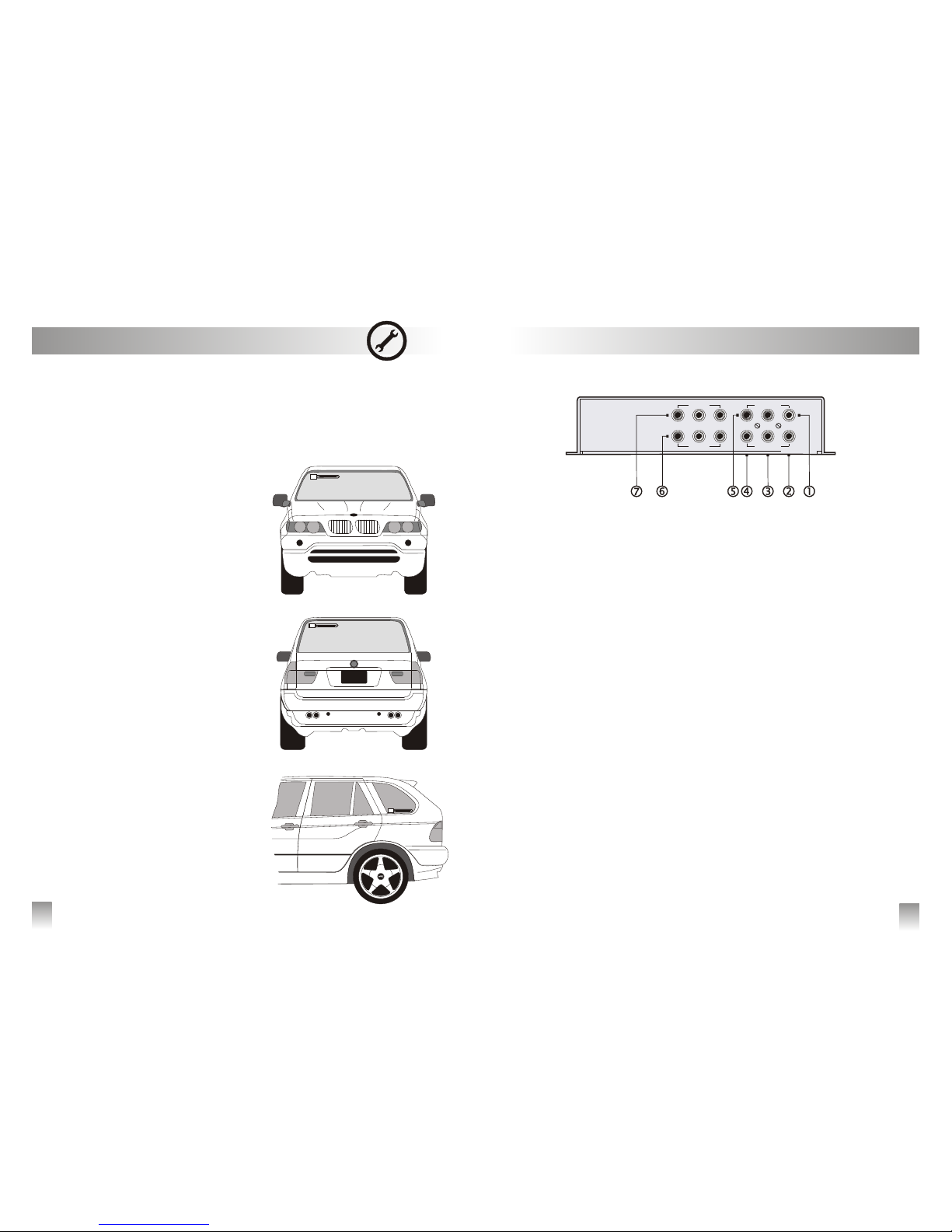
Rear Panel
7
i
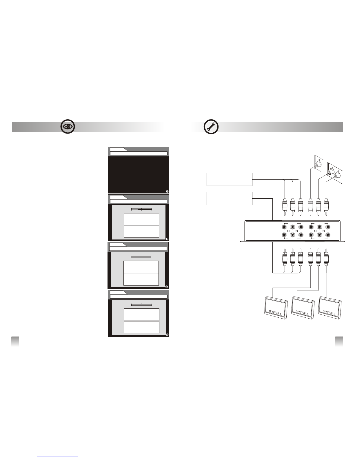
Installation and Connections
22
Œ
Ž
TV ANTENNAS
active antennas
s
(DVB-T).
vINSTALLATION GUIDELINES
•
‚
ƒ
•
•
,
•
•
Use only , amplified with adequate
gain, directly powered by the F antenna connector
(ANT IN) and suitable to the reception of the Digital
Terrestrial signal
Quantum Antennas, linked together with QTM10
receiver, have been manufactured in order to
optimize the system's functioning.
WARNING: do not provide external power in
case of use of different brand antennas, not to
occur in doing so may result in product
damages and in decay of warranty's terms.
Be sure to position the antennas as far away and
opposing from each other as possible. For exam-
ple, place the first antenna on the right side of the
wind screen of the vehicle and the second one
on the left side of the rear window or on the left
rear vent wing .
Antennas must be installed as far away from the
metal parts (vehicle's roof or vertical borders of
the wind screen/rear vent wing) as possible.
The bonnet or the boot (depending on the vehi-
cle) can influence whether positive or negative -
the signal reception. It's recommend to experi-
ment where to place the antennas whether on
the higher or the lower part of the window. The
higher part usually guarantees more protection
from noises caused by motorcycles and scooters.
Handle with care the coaxial cable setting in order
to avoid damages due to vibration or crushing.
Be sure that the connections have been correctly
set and check the screwing of the connectors. Sig-
nal reception's problems are often caused by
incorrect assembly.
RCA L/R AUDIO OUTPUT - Stereo
‚ RCA VIDEO OUTPUT - Front
Video output to connect to the front monitor’s
video input. Warning, signal is output only once
the handbrake is pulled
ƒ RCA VIDEO OUTPUT - Rear 1
Video output to connect to a rear monitor video
input. Signal is always available
„ RCA VIDEO OUTPUT - Rear 2
Video output to connect to a rear monitor video
input. Signal is always available
… RCA AUDIO OUTPUT - Mono
† AUDIO/VIDEO INPUT- A/V IN 2
Audio/Video inputs to connect an auxiliary unit
(e.g. Dvd player, rear camera, etc.). This input
can be selected by remote control
.
‡ AUDIO/VIDEO INPUT- A/V IN 1
Audio/Video inputs to connect an auxiliary unit
(e.g. Dvd player, rear camera, etc.). This input
can be selected by remote control
NOTE: video outputs and inputs according to PAL
Standard
frontrear 1rear 2
A/V IN 1
R
R
L
L
V
V
A/V IN 2
AUDIO OUT
R LM
VIDEO OUT