QUATRO
Air Technologies Inc.
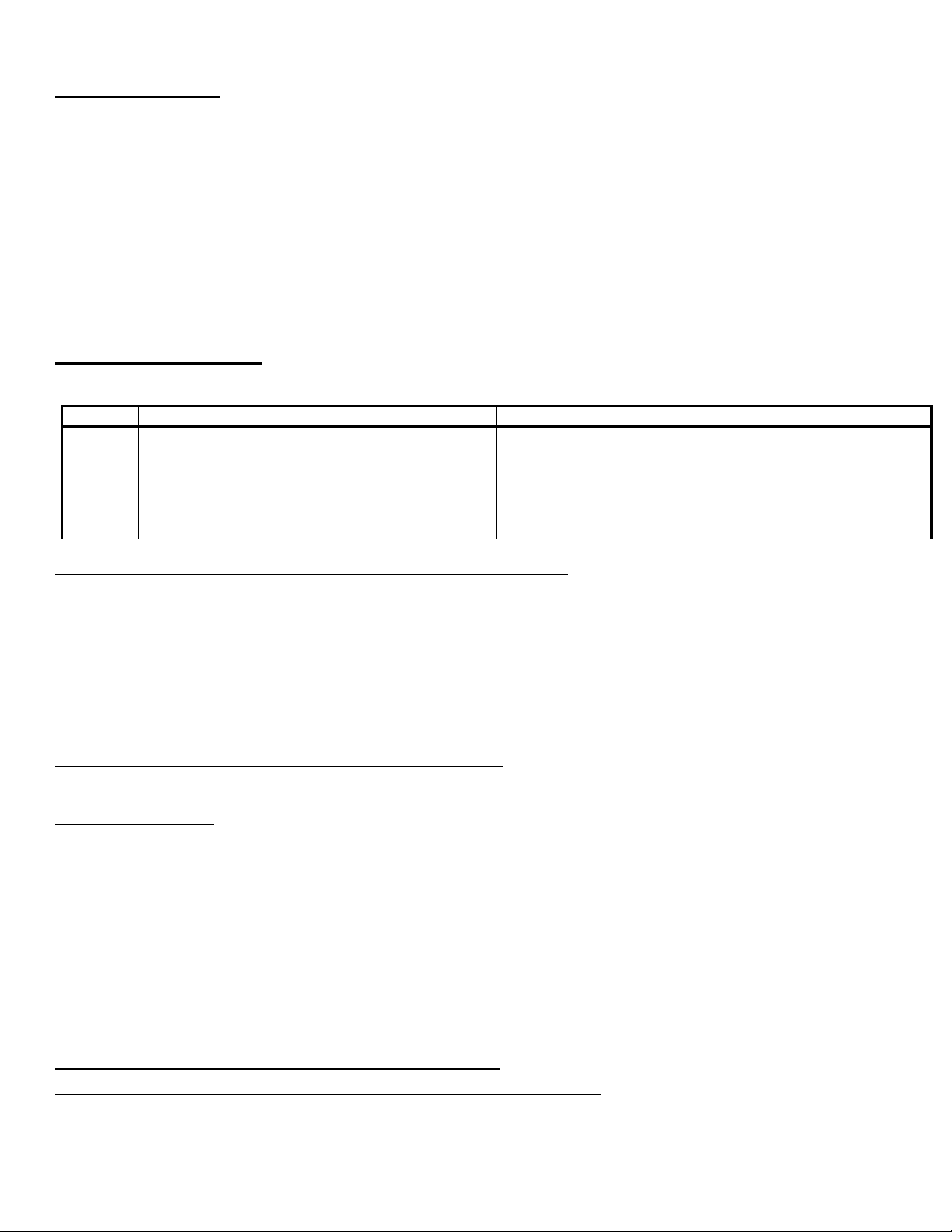
6
Remote Operation
If choosing the Dry Contact (closed contact) remote option, connect the black and red wires to anything that can close a
contact and short these 2 wires together.
If choosing the 1-30V AC/DC remote option, connect the white & the green wires to the remote signal. RESPECT THE
INDICATED POLARITY WHEN MAKING THIS CONNECTION. DO NOT EXCEED 30V AC/DC.
To enable the remote system startup for either remote option, first plug the system into power and then connect remote
cable. Then simply have the other piece of equipment close (short) the dry contact or supply a remote control voltage.
When the unit is stopped the Quatro System will shut down after a short delay.
After Remote Sensing Has Been Activated
If the unit is RECEIVING a remote signal: “System ON” & “Remote ON” Lights will be FULLY Illuminated
If the unit is WAITING FOR a remote signal: “System ON”will be OFF & “Remote ON” Lights will be FLASHING
Unplugging the power cord will automatically deactivate Remote Sensing Feature.
Remote Status
The System can output status signals to you equipment.
The Run Signal contact is CLOSED whenever the system is turned on (motor(s) are functioning).
The contact is OPEN when the unit is turned off (motor(s) are not functioning). This includes when the unit goes into
Remote/Standby & if the unit shuts down due to a problem.
Run signal will NOT open when the motor(s) shut off for a filter cleaning when operating in “Online” filter cleaning mode.
Critical Filter Pressure Alarms (high & low pressure) will OPEN the Run Signal and shut the motor(s) off.
The Fault Signal can be used either with a Normally Open (NO) or Normally Closed (NC) contact depending on which wire
you choose to use (see diagram on previous page).
When there ARE NO alarm conditions present the NO contact will remain open and the NC contact will remain closed.
When there ARE alarm conditions the NO contact will CLOSE and the NC contact will OPEN.
ALL LEVELS of Filter & Motor(s) service alarms will trip the Fault Signal.
The Quatro Run Signal can only shut down the piece of equipment controlling it remotely if the piece of equipment
supports that function. The piece of equipment must be set or programmed to shut itself off when the Quatro Run
signal is OPENED. Contact your equipment manufacturer to verify if your equipment supports that function.
The status signals can either return a “signal” provided by your equipment or output a 12VDC+ or 12VDC- depending on
how the AE427 remote cable is wired. The Quatro System uses a single “common” for both the Run & Fault Signals.
To return a “signal” connect your signal to the Brown wire (Pin 5).
The “returned” Run signal is available on the Violet wire (Pin 9).
The “returned” Fault NC (Normally Closed) is available on the Blue wire (Pin 6).
The “returned” Fault NO (Normally Open) is available on the Orange wire (Pin 7).
To be supplied with a 12vdc signal where the + is being switched connect the Yellow Wire (Pin 8) to the Brown wire (Pin 5).
The 12VDC+ Run signal is available across the Violet wire (Pin 9+) & the Black Wire (Pin 1-).
The 12VDC+ Fault NC (Normally Closed) is available across the Blue wire (Pin 6+) & the Black Wire (Pin 1-).
The 12VDC+ Fault NO (Normally Open) is available across the Orange wire (Pin 7+) & the Black Wire (Pin 1-).
Any combination of the Dry Contact, Run Signal & Fault Signal being used means the Black Wire (Pin 1) must be shared.
To be supplied with a 12vdc signal where the - is being switched connect the Black Wire (Pin 1) to the Brown wire (Pin 5).
The 12VDC- Run signal is available across the Violet wire (Pin 9-) & the Yellow Wire (Pin 8+).
The 12VDC+ Fault NC (Normally Closed) is available across the Blue wire (Pin 6-) & the Yellow Wire (Pin 8+)
The 12VDC+ Fault NO (Normally Open) is available across the Orange wire (Pin 7-) & the Yellow Wire (Pin 8+).
Any combination of the Dry Contact, Run Signal & Fault Signal being used means the Black Wire (Pin 1) must be shared.
Your “signal” will be managed as indicated on the table below. The combination of the Run & Fault Signals can tell you if
the unit is still running but has an alarm condition or if there is an alarm condition and the unit has shut down completely.