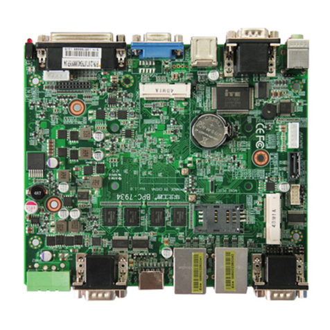
Norco BPC-7936 User manual

BPC-7936
USER' Manual V1.1

SZ HQ: 0755-27331166
Beijing Office: 010-82671166
Shanghai Office: 021-61212081
Chengdu Office: 028-85259319
Shenyang Office: 024-23960846
Xi’an Office: 029-88338386
Nanjing Office: 025-58015489
Wuhan Office: 027-87858983
Tianjin Office: 022-23727100
Singapore: 65-68530809
For more information, please visit:www.norco.com.cn
BPC-7936
USER' Manual V1.1

Announcement
With the exception of showing the accessories of product configuration,
this manual does not create any commitment of our company. We retained
the rights to change it without prior notice and will not be responsible for any
direct, indirect, intentional or unintentional damage or hidden dangers
caused by any improper installation or use.
Before buying products, please learn about the product performance
from the distributors to see if it is in line with your needs. NORCO is a
registered trademark of Shenzhen NORCO Intelligent Technology CO., LTD.
The ownership of other trademarks involved in this manual is owned by its
respective owners.
The contents of this manual are protected by copyright law. All rights
are strictly reserved. Any form of unauthorized reproduction is prohibited,
including but not limited to carbon copy, facsimile transmission and
electronic copy or email, etc.

Safety Instructions
1.Before using this product, please read this user’s manual carefully;
2.Any plate cards not ready to be installed shall be kept in the anti-static protective bags;
3.Before taking out the plate cards from the anti-static protective bags, first place hands on the
grounding metal object for a while so as to release the static electricity from your body and
hands;
4.While fetching the plate cards, please wear static protective gloves and have the habit of
holding the cards by edge;
5.Before connecting the motherboard to the power supply, please check the power voltage
6.In order to prevent bodily electric shock or damage to products, first turn off the AC power or
unplug the power cord out of power sockets while inserting main boards or plate cards or do
reconfiguration;
7.Before moving the plate cards or the unit, please make sure to unplug the AC power cords
out of the sockets;
8.Before you connect or unplug any equipment, please make sure that all power cords are
unplugged in advance;
9.To prevent any unnecessary damage to the products due to frequent power on/off. Please
wait at least 30 seconds before you restart up the unit after the unit is shut down;
10.If anything unexpected happened during the operating, please seek help from professionals;
11.This is a Class A product, in a domestic environment, this product may cause radio
interference. In this case, the user may be required to take adequate measures.

Content
Chapter 1 Product Introduction......................................................................................................... 1
1.1 Introduction.................................................................................................................................1
1.2 Hardware Specification............................................................................................................ 1
Chapter 2 Hardware Function.............................................................................................................4
2.1 Interface Location and Dimension Diagram..........................................................................4
2.2 Installation Steps....................................................................................................................... 5
2.3 Jumper Setting...........................................................................................................................5
2.3.1 CMOS Content Clearance /Keep Settings(JCC)................................................ 5
2.3.2 Hardware Switch for System Auto Boot upon Power On(JAT)..........................7
2.3.3 LCD Rated Voltage Selection Jumper(JP1,JP2)............................................. 7
2.4 Interface Specification.............................................................................................................. 8
2.4.1 Serial Port(COM1、COM2).....................................................................................8
2.4.2 SATA Port(SATA1、SATA2、JSATAPWR1、JSATAPWR2)........................... 10
2.4.3 USB、LAN Port(USB12、USB_LAN1、USB_LAN2)..................................... 11
2.4.4 Keyboard and mouse interface(KM)....................................................................12
2.4.5 Audio Port & Rear Panel LED(AUDIO,LINE-in,LED).................................. 12
2.4.6 display Interface(LVDS、VGA、HDMI).............................................................. 14
2.4.7 LVDS Power Supply Voltage(JLVDS)..................................................................15
2.4.8 Power Interface(PWR)...........................................................................................16
2.4.9 Fan Interface(FAN1,FAN2)................................................................................ 16
2.4.10 Programmable I / O Interface (JGPIO).................................................................. 18
2.4.11 Front Panel Interface(JFP)..................................................................................18
2.4.12 Expansion Slot........................................................................................................... 20
2.4.13 MINI IDE Interface(MINII DE )...........................................................................21
2.4.14 CF Card Interface...................................................................................................... 22
Chapter 3 BIOS Set up....................................................................................................................... 24
AMI BIOS Reflesh..................................................................................................................24
AMI BIOS Description........................................................................................................... 24
BIOS Parameter Setting....................................................................................................... 24
3.1 Main Menu................................................................................................................................25
3.2 Advanced..................................................................................................................................26
3.2.1 CPU Configuration.......................................................................................................27
3.2.2 IDE Configuration........................................................................................................ 28
3.2.3 Super IO Configuration............................................................................................... 32
3.2.4 Hardware Health Configuration................................................................................. 31
3.2.5 ACPI Configuration...................................................................................................... 32
3.2.6 AHCI Configuration......................................................................................................34
3.2.7 APM Configuration.......................................................................................................35
3.2.8 Remote Access Configuration................................................................................... 36
3.2.9 USB Configuration.......................................................................................................37
3.2.10 Onboard LAN Configuration.................................................................................... 39
3.3 Chipset Menu...........................................................................................................................40
3.3.1 North Bridge..................................................................................................................41
3.3.2 South Bridge.................................................................................................................44
3.4 PCIPnP..................................................................................................................................... 45
3.5 Boot Menu................................................................................................................................ 46
3.6 Security Menu..........................................................................................................................48
3.7 Save&Exit Menu......................................................................................................................41
Appendix................................................................................................................................................48
Appendix 1:Watchdog Programming Guide........................................................................... 42
Appendix 2:Glossary.................................................................................................................. 43
Appendix 3:Driver Installation................................................................................................... 46

Packing List
Thanks for purchasing NORCO products. Please check the
accessories as per the packing list when you open its package. If you find
any defect components or anything damaged or lost, please contact your
vendor ASAP.
■ BPC-7936
■ Driver CD
1pcs
1pcs

Chapter
One
Product
Introdu
ction

BPC-7936 V1.1 User's Manual
1
Chapter One Product Introduction
1.1 Introduction
BPC-7936 is NORCO’s latest motherboard based on Intel Cedarview platform special
for NORCO box computer ,support Intel Cedarview D2550 processor. On board 2GB/4GB
DDRⅢ800/1066MHz memory,memory up to 4GB;Support LVDS、VGA、HDMI display port,
support independent dual display ;Provide 2x standard DB9 COM ports (support
RS232/RS422/RS485);2xstandard SATA3.0 port,1xIDE port and CF card port;2 x standard
double-layer USB2.0 port and one 2x5Pin pin;2xLAN port,support 1XMic_in,1XSpeaker_out,
8BitsGPIO ;1x standard mouse and keyboard interface. It can meet the needs of most
professional customers in the current market. It can provide perfect hardware solutions for
digital signage, POS machine, self-service terminal, industrial automation and other fields.
1.2 Hardware Specification
Size
●Size:180mmX150mm
Processor
●Intel Cedarview D2550 processor
Chipset
●Chipset:NM10
System Memory
●On board 2GB/4GB DDRⅢ800/1066MHz memory,memory up to 4GB
Display
●Display port:LVDS,HDMI,VGA
●VGA:1xVGA port,resolution support : 1920x1200@60Hz;Standard DB15 port
●LVDS:1xLVDS port,single channel 24bit,maximum supported resolution: 1440x900@60Hz,
default resolution : 800X600@60Hz;;2X12 double row pin to connect expansion board

BPC-7936 V1.1 User's Manual
2
●HDMI :1xHDMI port ,resolution support: 1920x1200 @ 60Hz ;Support independent dual
displays
Ethernet
●Network controller:Adopt PCIe interface chip,model: 82583V
●Rate:10/100/1000MBps
●Support Wake On LAN(WOL)
Storage
●Support SATAI/SATAII/SATAIII
●Provide 2xstandard 7Pin SATA2.0 port and 2x5Pin HDD power supply voltage interface
●Provide 1xCF card and IDE interface
Audio
●Adopt ALC887 audio control chip,support dual channel,stereo
●Interface:Provide 2x tip jacks(Pink for MIC-in,Green for Speak-out)
I/O
●I/O chip:W83627DHG
●Serial port:provide 2xserial port,support RS232/RS422/RS485 mode
USB
●Provide 2x double-layer USB2.0 port and one 2x5Pin USB pin
KBMS
●Provide 1x standard PS/2 mouse & keyboard interface
Expansion port
●One 2X25pin pin,support LCP bus,1x SATA3.0,2x USB2.0,1 x PCIEX1
Power supply
●Support single power +12V supply,supports hardware and software switch for system auto
boot upon power on

BPC-7936 V1.1 User's Manual
3
Watchdog
●Super I/O,support hardware reset
BIOS
●64M bit SPI BIOS
Operating Environment
●Operating Temperature:0℃~60℃
●Storage Temperature:-40~85℃
●Operating Humidity:5%~95%,non-condensing
●Storage Humidity:5%~95%,non-condensing

Chapter
Two
Hardware
Function

BPC-7936 V1.1 User's Manual
4
Chapter Two Hardware Function
2.1 Interfaces Location and Dimension
Following picture illustrates the front interfaces and dimension of board BPC-7936. Please
pay attention to the installation process. Improper installation of some components may lead to
system failure.
Note: When installing the board, please wear anti-static gloves in case of any electrostatic
damage caused during the installation.

BPC-7936 V1.1 User's Manual
5
2.2 Installation Steps
Please follow the steps below to assemble your computer:
1.Adjust all jumpers onboard BPC-7936 according to the user manual.
2.Install other expansion cards.
3.Connect all signal line, cables, panel control circuit and power adapter.
4.Start the computer and finish BIOS settings.
Key components of this motherboard are Integrated circuit and these components could
be easily damaged by electrostatic influence. So, before installing this unit, please always keep
the following precautions in mind:
1.Please hold the board by edges and don’t touch any components or plug and socket pins.
2.Wear anti-static gloves/wrist strap while touching the integrated circuit components, such as
CPU, RAM, etc.
3.Put those unused or uninstalled components in static shielding bags or trays.
4.Please first check the power switch is off before connecting the power plug.
2.3 Jumper Settings
Please refer to following instructions to do jumper settings before installing the motherboard.
Remark: How to identify the PIN1 of all jumpers and interfaces: Please observe the word mark
on the side of the plug socket, which will be a “1” or bold line or triangular symbol; And please
look at the back of PCB, each with a square shape will be the PIN 1; and all the jumpers’ PIN1
have a white arrow on the side.
2.3.1 CMOS Clear/Hold Jumper Setting(JCC)
CMOS is powered by the onboard button cells. Clear CMOS may lead to permanent
elimination of previous system settings and make the system back to the original settings
(factory default).
Steps:(1)Shut down the computer and disconnect power supply;
(2)Make the jumper JCC Pin1 and Pin 2 short for 5~10 seconds(Pin1-2)and then make it
back to default setting with Pin2-3 connected;
(3)Start the computer and press <Del> to enter BIOS setup, then reload optimal defaults;
(4)Save and Exit.

BPC-7936 V1.1 User's Manual
6
JCC:
Setting
JCC
1-2
Clear CMOS,BIOS renew to initialization
2-3
Normal status (default)
Do not clear CMOS when power on, otherwise it will damage the motherboard!
JCC

BPC-7936 V1.1 User's Manual
7
2.3.2 Hardware Switch for System Auto Boot upon Power On(JAT)
JAT:
Setting
JAT
Open
Disable Auto Boot
Close
Enable Auto Boot
2.3.3 LCD Rated Voltage Selection Jumper(JP1,JP2)
Before using LCD, please know its required working rated voltage. Here jumper sets the
output voltage of 41PIN and 42PIN of LVDS socket for LCD display logic circuit.
JAT

BPC-7936 V1.1 User's Manual
8
JP1、JP2:
Setting
3.3V
5V
12V
JP1
1-2
2-3
×
JP2
×
×
1-2
2.4 Interface Specification
When connecting external connectors, please read this manual carefully in order to avoid
damage to the motherboard!
2.4.1 Serial Port(COM1、COM2)
Board with 2x standard DB9 serial port COM,support RS232/RS422/RS485 transmission
mode.
JP1
JP2

BPC-7936 V1.1 User's Manual
9
COM
Pin
Signal Name
1
DCD
2
RXD
3
TXD
4
DTR
5
GND
6
DSR
7
RTS
8
CTS
9
RI
When COM1、COM2 are set to R232/RS422/RS485,definition of PIN:
Pin
RS232(default)
RS422
RS485
1
DCD
TX-
DATA-
2
RXD
TX+
DATA+
3
TXD
RX+
NC
4
DTR
RX-
NC
5
GND
GND
GND
COM1、COM2

BPC-7936 V1.1 User's Manual
10
6
DSR
NC
NC
7
RTS
NC
NC
8
CTS
NC
NC
9
RI
NC
NC
2.4.2 SATA Port(SATA1、SATA2、JSATAPWR1、JSATAPWR2)
Provide 2x standard 7Pin SATA port, and 2x5Pin HDD power supply voltage interface
(SATA1 port and MINI IDE port alternative).
SATA1/2:
Pin
Signal Name
1
GND
2
TX+
3
TX-
4
GND
5
RX-
6
RX+
7
GND
SATA2
SATA1
JSATAPWR2
JSATAPWR1

BPC-7936 V1.1 User's Manual
11
JSATAPWR1/2:
Pin
Signal Name
1
+3.3V
2
GND
3
+5V
4
GND
5
+12V
2.4.3 USB、LAN Port(USB12、USB_LAN1、USB_LAN2)
Provide 2xstandard double layer USB2.0 port and one 2x5Pin pin. Provide 2xstandard
LAN network interface, support Wake On LAN(WOL).
USB12:
Signal Name
Pin
Pin
Signal Name
+5V
1
2
GND
USBD_N1
3
4
GND
USBD_P1
5
6
USBD_P2
USB_LAN1
USB_LAN2
USB12
Table of contents
Other Norco Motherboard manuals

Norco
Norco MITX-6930 User manual

Norco
Norco SOM-6503 User manual

Norco
Norco EMB-7536 User manual

Norco
Norco ATX-6991 User manual

Norco
Norco EMB-7541 User manual

Norco
Norco BPC-7971 User manual

Norco
Norco MITX-6854 User manual

Norco
Norco MITX-6892 User manual

Norco
Norco MITX-6922 User manual

Norco
Norco EMB-4850 User manual

Norco
Norco MITX-6891 User manual

Norco
Norco MITX-6110 User manual

Norco
Norco MATX-6959 User manual

Norco
Norco SOM-6670 User manual

Norco
Norco MITX-6973 User manual

Norco
Norco EMB-3503 User manual

Norco
Norco BPC-7934 User manual

Norco
Norco FWMB-7550 User manual

Norco
Norco EMB-7540 User manual

Norco
Norco MITX-6922 User manual