PleaseReadCarefully
Please read and follow all instructions as they have important
safety instructions warning to a risk of re, electric shock, or injury
to a person or persons using the Quest Q1 water sanitiser.
lThis appliance is not intended for use by persons with reduced
physical, sensory or mental capabilities, or lack of experience
and knowledge.
lKeep the appliance located away from children or if this is
not possible make sure an adult is present at all times when
the pool sanitisation system is working. Cleaning and user
maintenance should not be made by children.
l To reduce the risk of injury, service should only be attempted
by a suitably qualied Quest pool authorised dealer or agent.
lDo not operate an electrolytic cell without water circulation in
the cell. A build-up of gases will result in hazardous conditions.
lIf you employ a pool maintenance contractor, ensure that they
read and follow these instructions as this freshwater system
diers from common chlorine / salt sanitisers.
The best results with the freshwater system are obtained by
following a few simple rules:
lDo not use stabiliser.
lDo not use bromine compounds.
l Do not use aluminium based or any other occulants.
lDo not use Soda Ash.
lDo not use Granular Chlorine. The use of Granular Chlorine
may cause black staining of the pool rendering if it is added
undiluted to a pool treated by our System.
lDo not throw un-dissolved chemicals into the pool. Clean the
pool lter regularly.
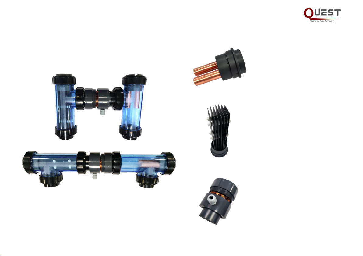
1.1 System Operation
Thank you for purchasing your Quest Q-1 freshwater pool sanitiser.
Follow the instructions below and you will enjoy the benets of low
maintenance and the exceptional water quality achievable with
this system. During periods of intense use or when there has been
signicant water dilution or contamination more frequent testing
and active management may be required.
Warning
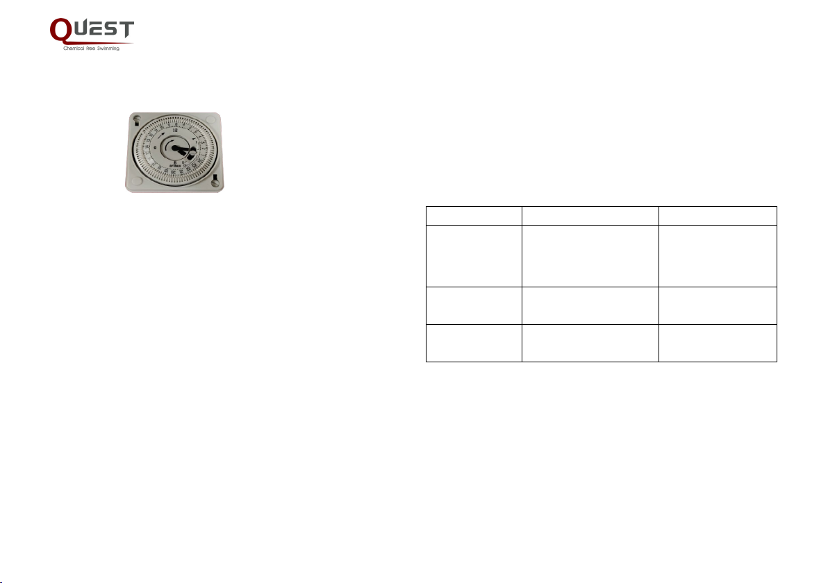
It is important that the Q-1 system only be allowed to operate
when the pool pump is running so that water is owing through the
ionisation/oxidation chamber and the EM descaler when they are in
operation.
Normal drinking water can have a mineral imbalance for use in a
swimming pool. In those areas where mineral imbalance exists, the
pool water will need initial balancing. A balanced pool is necessary
for proper disinfection and will assure freedom from possible
staining and scaling problems. Mineral imbalance and improper
pH control can signicantly complicate maintenance and have a
serious deteriorating eect on the pool itself. After initial balancing
of the water, mineral balance must be maintained within the
proper parameters to provide continued protection and ease of
maintenance. Frequency of testing is dependent on weather and
pool load.
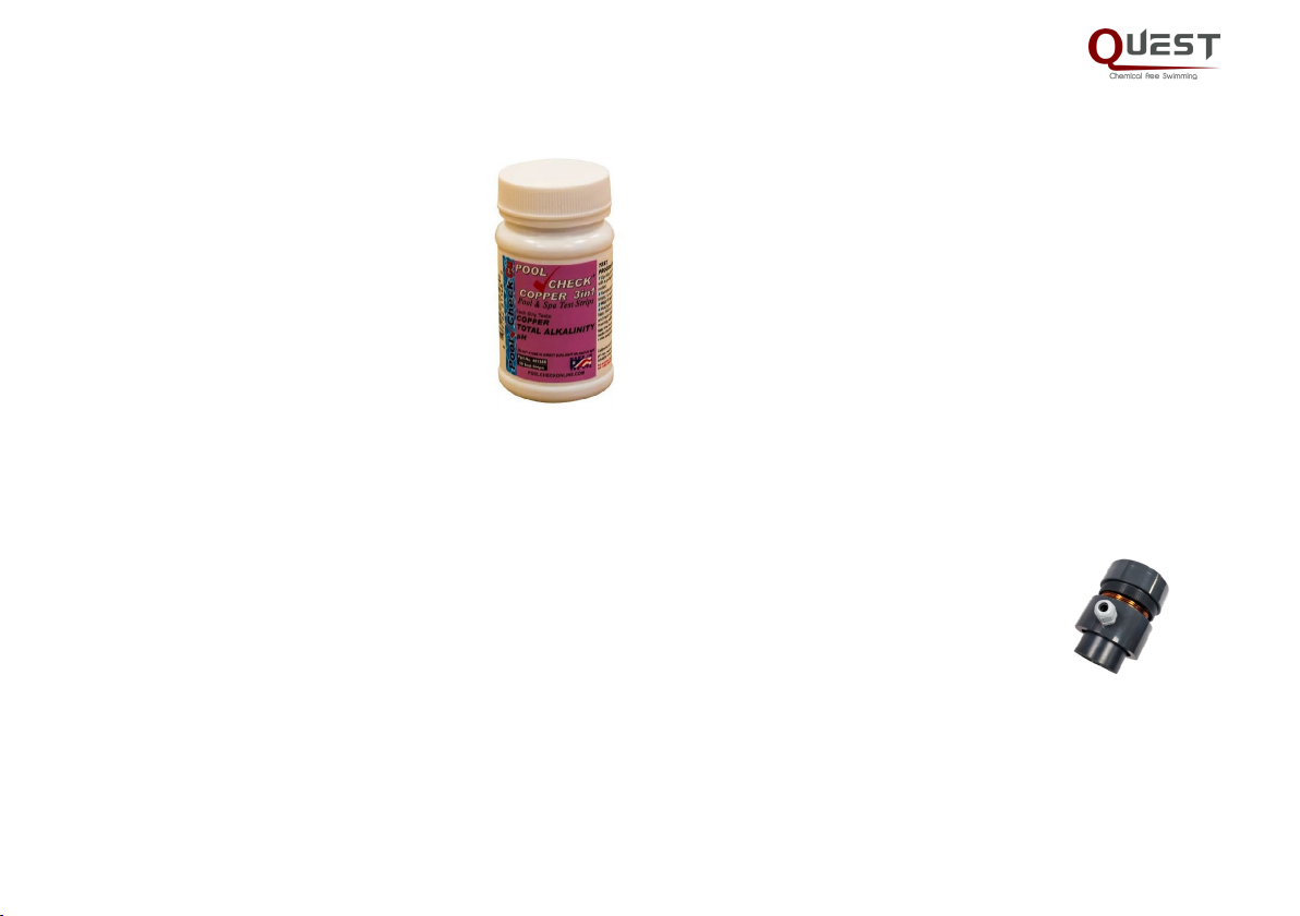
Do not allow the pool to run a high pH and or high Copper levels.
This is easily avoided by regular testing. We recommend that you
test the pool water every two weeks with the test kit provided.
The chemicals required to keep your pool balanced and healthy
will be a buer such as sodium bicarbonate and hydrochloric acid.
In addition you should ensure pool cleaning to remove leaves and
dust as usual, as these use up the sanitiser and provide nutrients
for algae and bacteria growth.
2