Quickie Integrated C.G. Tilt P-220 Guide

Quickie®P-220 User
Instruction
Manual &
Warranty
Supplier:
This manual must be given to
the rider of this wheelchair.
Rider:
Before using this wheelchair
read this entire manual and
save for future reference.

930475 Rev. A
I. Introduction 3
SUNRISE LISTENS
Than you for choosing a Quic ie wheelchair. We want to hear your questions
or comments about this manual, the safety and reliability of your chair, and the ser-
vice you receive from your Sunrise supplier. Please feel free to write or call
us at the address and telephone number below:
Sunrise Medical
Customer Service Department
7477 East Dry Cree Par way
Longmont, Colorado 80503
(303) 218-4500 or (800) 333-4000
Be sure to return your warranty card, and let us now if you change your address. This
will allow us to eep you up to date with information about safety, new products and
options to increase your use and enjoyment of this wheelchair. If you lose your war-
ranty card, call or write and we will gladly send you a new one.
FOR ANSWERS TO YOUR QUESTIONS
Your authorized supplier nows your wheelchair best, and can answer most of your
questions about chair safety, use and maintenance. For future reference, fill in
the following:
Supplier: ______________________________________________________________________________
Address: _______________________________________________________________________________
______________________________________________________________________________________
Telephone: _____________________________________________________________________________
Serial #: _______________________________________ Date/Purchased: ________________________

930475 Rev. A
II. Table of Contents 5
IX. SET UP, ADJUSTMENT & USE ................................................................................ 27
Notes ................................................................................................................ 27
Tools You Will Need............................................................................................. 28
Chec Out .......................................................................................................... 28
A. Power Drive Unit ............................................................................................ 29
B. Battery Removal............................................................................................. 29
C. Folding Bac rest............................................................................................. 30
D. Footrests....................................................................................................... 30
E. Elevating Legrests (Optional) ........................................................................... 31
F. Integral Joystic Installation ........................................................................... 31
G. Remote Joystic Installation (Optional)............................................................. 31
H. To Adjust the Height of the Remote Joystic (Optional) ....................................... 31
I. Remote Joystic Swing-Away Retractable Mount (Optional) .................................. 32
J. Dual-Post Height-Adjustable Armrests................................................................ 32
K. Single Post Height-Adjustable Armrests (Optional) .............................................. 32
L. Seat Depth .................................................................................................... 33
M. 10" Drive Wheel ............................................................................................. 34
N. Dynamic Stabilizer .......................................................................................... 34
MANUAL WHEELCHAIR CONVERSION KIT .............................................................. 35
A. Joystic ........................................................................................................ 35
B. Power Drive Unit ............................................................................................ 35
C. Wheel Loc s .................................................................................................. 35
D. 24" Rear Wheels............................................................................................. 36
E. Anti-Tip Tubes ............................................................................................... 36
F. Installation of Axle Tube Assembly.................................................................... 36
G. Chec -Out ..................................................................................................... 37
X. OPERATING GUIDE.............................................................................................. 38
A. Performance Control Settings ........................................................................... 38
B. Quic ie QTRONIX Programmer Pad (Optional) ...................................................... 38
C. Thermal Roll-Bac ........................................................................................... 39
D. Circuit Brea ers.............................................................................................. 39
E. Integral Joystic ............................................................................................ 40
F. Remote Joystic Assembly (Optional) ................................................................ 41
G. Motor Loc s................................................................................................... 43
XI. BATTERIES ......................................................................................................... 44
A. Introduction .................................................................................................. 44
B. Battery Charger.............................................................................................. 45
C. Acid Burns..................................................................................................... 46
D. Connecting Batteries in Battery Compartment..................................................... 46
E. Charging Batteries.......................................................................................... 47
F. Disposing of Batteries..................................................................................... 48
XII. MAINTENANCE ................................................................................................... 49
A. Notes ........................................................................................................... 49
B. Cleaning ....................................................................................................... 49
C. Storage Tips .................................................................................................. 49
D. Battery Maintenance ....................................................................................... 50
E. Pneumatic Tires.............................................................................................. 51
F. To Repair or Replace a Tire .............................................................................. 51
G. Ordering Parts................................................................................................ 52
H. Maintenance Chart.......................................................................................... 52
XIII. WIRING DIAGRAM .............................................................................................. 53
XIV. SUNRISE LIMITED WARRANTY .............................................................................. 55
II. Table of Contents
930475 Rev. A
4
I. INTRODUCTION .................................................................................................. 3
II. TABLE OF CONTENTS ........................................................................................... 4
III. YOUR CHAIR AND ITS PARTS ............................................................................... 6
IV. NOTICE - READ BEFORE USE ................................................................................ 8
V. EMI (ELECTROMAGNETIC INTERFERENCE) .............................................................. 9
A. What is EMI................................................................................................... 9
B. What Effect Can EMI Have ............................................................................... 9
C. Sources of EMI ............................................................................................... 10
D. Distance From the Source ................................................................................ 10
E. Immunity Level .............................................................................................. 10
F. Report All Suspected EMI Incidents................................................................... 11
G. EMI From Chair .............................................................................................. 11
VI. GENERAL WARNINGS .......................................................................................... 12
A. Notice to Rider............................................................................................... 12
B. Notice to Attendants....................................................................................... 12
C. Weight Limit.................................................................................................. 13
D. Controller Settings.......................................................................................... 13
E. EMI .............................................................................................................. 13
F. Safety Chec list ............................................................................................. 13
G. Changes & Adjustments................................................................................... 14
H. When Seated in a Par ed Wheelchair ................................................................. 14
I. Environmental Conditions ................................................................................ 14
J. Terrain .......................................................................................................... 15
K. Street Use ..................................................................................................... 15
L. Motor Vehicle Safety ....................................................................................... 15
M. Center of Balance ........................................................................................... 16
N. Transfers ....................................................................................................... 16
O. Reaching or Leaning ....................................................................................... 17
P. Dressing or Changing Clothes ........................................................................... 17
Q. Obstacles ...................................................................................................... 18
R. Driving in Reverse .......................................................................................... 18
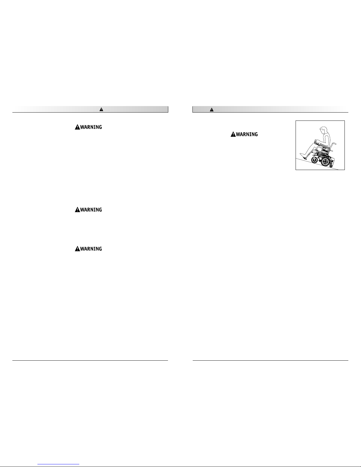
S. Ramps, Slopes & Sidehills ................................................................................ 18
T. To Reduce the Ris of Falls, Tip-over or Loss of Control........................................ 19
U. Ramps at Home & Wor ................................................................................... 20
V. Wheelchair Lifts ............................................................................................. 20
W. Curbs & Single Steps....................................................................................... 21
X. Stairs ........................................................................................................... 21
Y. Escalators...................................................................................................... 21
VII. WARNINGS: COMPONENTS & OPTIONS................................................................... 22
A. Anti-Tip Levers .............................................................................................. 22
B. Armrests ....................................................................................................... 22
C. Batteries....................................................................................................... 22
D. Cushion & Sling Seats ..................................................................................... 22
E. Fasteners ...................................................................................................... 23
F. Footrests....................................................................................................... 23
G. Motor Loc .................................................................................................... 23
H. On/Off Switch ................................................................................................ 23
I. Pneumatic Tires.............................................................................................. 24
J. Positioning Belts (Optional)............................................................................. 24
K. Push Handles................................................................................................. 24
L. Rear Wheel Loc s (Optional) ............................................................................ 25
M. Seating Systems ............................................................................................. 25
N. Upholstery Fabric ........................................................................................... 25
VIII. TIPS FOR ATTENDANTS ........................................................................................ 26
A. To Climb a Curb or Single Step ......................................................................... 26
B. To Descend a Curb or Single Step...................................................................... 26

930475 Rev. A
III. Your Chair and Its Parts 7
Weight
115 lb. (52 g) with swing-away
footrests and armrests, without
batteries
Drive Wheels
12" x 4" Mag (260 mm)
Tire types: Standard - pneumatic
Option - 12" x 2"
Option - airless insert
Joystic
Standard - Integral
Option - Remote (right-hand or left-
hand mount)
Option - swing-away retractable,
USCM (Universal Specialty Control
Module)
Batteries
(2 deep cycle batteries required to oper-
ate chair)
Option - Group 24 gel or 22NF gel
Battery Charger
Standard - 5 amp
Option - 8 amp dual mode
Seat Frame Dimensions
Frame width: Standard - 16", 18"
(406, 457 mm)
Option - 14", 15", 17", 19", 20", 22", 24"
(356, 381, 432, 482, 508, 558, 609mm)
Seat depth: 14"-20"(356 - 508 mm)
Seat height: Standard - 18" (458 mm),
option- 19" (508 mm), 20" (508 mm)
Seat sling: Standard - parapa ,
Option - aluminum seat pan
Option-cushion: 2" (50mm)
Bac rest Folding
Standard - 15.5" (393 mm)
Option - 17.5", 19.5"
(445 mm, 495 mm)
Caster For
Standard - fixed
Option - Suspension (8" tire only)
Footrest
Standard - Swing-away with compos-
ite footplates and heel loops, or two
piece loc ing.
Option - fixed tapered (80°) or fixed
straight (70°), elevating legrests,
angle-adjustable footplate, extended,
toe loops, extension tubes, solid one-
piece, two piece loc ing
Casters
Standard - 8" (200mm) pneumatic
Option - 8" (200mm) airless insert
8" (200mm) suspension
9" (225mm) pneumatic
9" (225mm)airless insert
Armrests
Standard - dual post with standard or
full length pad
Option - dual post height-adjustable,
height-adjustable with standard or
full length pad
Manual Wheelchair Conversion Kit
Conversion Kit Axles
Option - quad-release axle nuts
Rear Wheels
Standard - Mag
Tire types: pneumatic, airless
insert, full-profile polyurethane,
low-profile polyurethane, Kevlar,
high-pressure clincher
Handrim
Standard - aluminum
Option - plastic-coated, long tabs
vertical or oblique projections
Wheel Loc s
Standard - Push-to-loc
Option - pull-to-loc
6" or 9" (150 mm or 230 mm)
extension handles
All features may not be available with some
chair setups or in conjunction with another
chair feature. Please consult your supplier for
more information. Your authorized supplier
can also provide you with more information
on accessories.
The Quic ie P-220 is a class B wheelchair as
defined in EN 12184
III. Your Chair and Its Parts
930475 Rev. A
6
1. Armrest
2. Joystic (optional remote shown)
3. Seat cushion (optional)
4. Fixed front hanger
5. Caster tire
6. Two-piece, loc ing, flip-up foot-
plate
7. Bac rest
8. Push handle
9. Bac rest hinge plate
10. Free-wheel Release Lever
11. Seat frame
12. Dynamic stabilizer
13. Drive wheels
14. Base Frame
15. Caster For
Quickie P-220
1
2
3
4
5
6
7
8
9
10
11
12
13
14
15

930475 Rev. A
V. EMI (Electromagnetic Interference) 9
Heed all warnings to reduce the ris of unintended bra e release or chair
movement:
1. Beware of the danger from hand-held transceivers. Never turn on or use a
hand-held transceiver while power to your chair is on. Use extra care if you
believe that such a device may be in use near your chair.
2. Be aware of nearby radio or TV stations, and avoid coming close to them.
3. If unintended movement occurs, turn your chair off as soon as it is safe to
do so.
A. WHAT IS EMI?
1. EMI means: electromagnetic (EM) interference (I). EMI comes from radio wave
sources such as radio transmitters and transceivers. (A “transceiver” is a device
that both sends and receives radio wave signals).
2. There are a number of sources of intense EMI in your daily environment.
Some of these are obvious and easy to avoid. Others are not, and you may not
be able to avoid them.
3. Powered wheelchairs may be susceptible to electromagnetic interference (EMI)
emitted from sources such as radio stations, TV stations, amateur radio (HAM)
transmitters, two way radios, and cellular phones.
4. EMI can also be produced by conducted sources or electro-static discharge (ESD).
B. WHAT EFFECT CAN EMI HAVE?
1. EMI can cause your chair, without warning, to:
•Release its bra es
•Move by itself
•Move in unintended directions
If any of these occurs, it could result in severe injury to you or others.
2. EMI can damage the control system of your chair. This could create a safety
hazard, and lead to costly repairs.
IV. Notice– Read Before Use
930475 Rev. A
8
A. CHOOSE THE RIGHT CHAIR & SAFETY OPTIONS
Sunrise provides a choice of many power wheelchair styles, sizes and adjustments to
meet the needs of the rider. However, final selection of a wheelchair rests solely with
you and your health care professional. Choosing the best chair for you depends on
such things as:
1. Your size, disability, strength, balance and coordination.
2. Your intended use, and your level of activity.
3. The types of hazards you must overcome in daily use (in areas where you are
li ely to use your chair).
4. The need for options for your safety and comfort (such as positioning belts
or special seat systems).
B. ADJUST CHAIR TO YOUR ABILITY
You need to wor with your doctor, nurse or therapist, and your supplier, to fit this
chair and adjust the controller settings for your level of function and ability.
C. REVIEW THIS MANUAL OFTEN
Before using this chair you, and each person who may assist you, should read this
entire Manual and ma e sure to follow all instructions. Review the warnings often,
until they are second nature to you.
D. WARNINGS
The word “WARNING” refers to a hazard or unsafe practice that may cause severe injury or
death to you or to other persons. The “Warnings” are in four main sections, as follows:
1. V — EMI
Here you will learn about electromagnetic interference and how it can affect your
chair.
2. VI — GENERAL WARNINGS
Here you will find a safety chec list and a summary of ris s you need to be
aware of before you ride this chair.
3. VII — WARNINGS — COMPONENTS & OPTIONS
Here you will learn about your chair. Consult your supplier and your health care
professional to help you choose the best set-up and options for your safety.
4. XI — BATTERIES
Here you will learn about battery and charger safety, and how to avoid injury.
NOTE– Where they apply, you will also find “Warnings” in other sections of this
Manual.

930475 Rev. A
V. EMI (Electromagnetic Interference) 11
4. The following specialty input devices have an un nown effect on the immunity level
because they have not been tested with the P-220 and QTRONIX control system:
•Breath Control • Proportional Head Control
•Tri-Switch Head Array • Proportional Mini-Joystic /Chin Control
•Heavy Duty Switched Joystic • Buddy Button
•Treadle Switch • Micro Light
•Ribbon Switch • Star Board
•Proximity Head Array • Wafer Board
•Zero Touch Switch • Penta Switch
•4-Zero Touch Switch • Plate Switch
•5-Zero Touch Switch • Soft Switch
•Disc Switch • Grasp Switch
•Wobble Switch
Individuals with physical limitations requiring the use of a specialty control
input device nown not to be immune to 20V/m, or not nown, should exer-
cise extra care around nown sources of EMI.
There is no way to now the effect on EMI if you add accessories or modify
this chair. Any change to your chair may increase the ris of EMI. Parts not
specifically tested or parts from other suppliers have un nown EMI properties.
F. REPORT ALL SUSPECTED EMI INCIDENTS
You should promptly report any unintended movement or bra e release.
Be sure to indicate whether there was a radio wave source near your chair
at the time. Contact:
Sunrise Medical, Customer Service Department at (800) 333-4000.
G. EMI FROM CHAIR
The chair itself can disturb the performance of electromagnetic fields such as emitted
by alarm systems of shops.
V. EMI (Electromagnetic Interference)
930475 Rev. A
10
C. SOURCES OF EMI
The sources of EMI fall into three broad types:
1. Hand-Held Transceivers:
The antenna is usually mounted directly on the unit. These include:
• Citizens band (CB) radios
• “Wal ie-tal ies”
• Security, fire and police radios
• Cellular phones
• Lap-top computers with phone or fax
• Other personal communication devices
NOTE– These devices can transmit signals while they are on, even if not in use.
2. Medium-Range Mobile Transceivers:
These include two-way radios used in police cars, fire truc s, ambulances and taxi
cabs. The antenna is usually mounted on the outside of the vehicle.
3. Long-Range Transceivers:
These include commercial radio and TV broadcast antenna towers and
amateur (HAM) radios. NOTE– The following are not li ely to cause EMI problems: Lap-
top computers (without phone or fax), Cordless phones, TV sets or AM/FM radios, CD or
tape players.
D. DISTANCE FROM THE SOURCE
EM energy rapidly becomes more intense as you get closer to the source. For this rea-
son, EMI from hand-held devices is of special concern. (See C.1 above) A person
using one of these devices can bring high levels of EM energy very close to your chair
without you nowing it.
E. IMMUNITY LEVEL
1. The level of EM is measured in volts per meter (V/m). Every power wheelchair
can resist EMI up to a certain level. This is called its “immunity level”.
2. The higher the immunity level, the less the ris of EMI. It is believed that a
20 V/m immunity level will protect the power wheelchair user from the more
common sources of radio waves.
3. The configuration tested and found to be immune to at least 20 V/m is:
Quic ie P-220 power wheelchair with a right-hand mounted QTRONIX remote joy-
stic system, 18" seat width, 18" seat depth, dual post height adjustable arm-
rests, fixed tapered legrests with one piece solid footplate, and Gp 24 gel cell
batteries.

930475 Rev. A
VI. General Warnings 13
C. WEIGHT LIMIT
1. The rider plus items carried should never exceed a total weight of 300 pounds.
2. Never use this chair for weight training if the total weight (rider plus
additional weights) exceeds 300 pounds.
3. Exceeding the weight limit is li ely to damage the seat, frame, or fasteners, and
may cause severe injury to you or others from chair failure.
4. Exceeding the weight limit will void the warranty.
D. CONTROLLER SETTINGS
Be aware that you may need to adjust the controller settings of your chair to reduce
the ris of a collision, fall or tip-over.
1. Chec and adjust the settings every six to twelve months (or more often, if needed).
2. Consult your supplier to adjust the control settings immediately if you notice
any change in your ability to:
•Control the joystic
•Hold your torso erect
•Avoid running into objects.
E. EMI
Read Section V to learn about EMI. To reduce the ris of unintended bra e release or
chair movement:
1. Never turn on or use a hand-held transceiver while power to your chair is on.
Use extra care if you believe that such a device may be in use near you chair.
2. Be aware of nearby radio or TV stations, and avoid coming close to them.
3. If unintended movement or bra e release occurs, turn your chair off as soon
as it is safe.
F. SAFETY CHECK-LIST
Before each use of this chair:
1. Ma e sure the chair operates smoothly. Chec for noise, vibration, or a change in
ease of use. (They may indicate low tire pressure, loose fasteners, or damage to
your chair).
•If you detect a problem, ma e sure to repair or adjust the chair. Your supplier
can help you find and correct the problem.
2. Ma e sure batteries are charged. Green lights on charge indicator will light up
when charge is full. Yellow lights indicate battery charge level is getting low.
Red lights indicate batteries are in immediate need of charging.
VI. General Warnings
930475 Rev. A
12
Heed all warnings in this section. If you fail to do so a fall, tip-over or loss
of control may occur and cause severe injury to you or others.
A. NOTICE TO RIDER
1. Before using this chair, you should be trained in its safe use by your health care
professional.
2. Every wheelchair is different. Ta e the time to learn the feel of this chair before
you begin riding.
3. Be aware that you must develop your own methods for the safe use of this chair,
that are best suited to your level of function and ability.
4. Have someone help you practice bending, reaching and transfers until you learn
how to do them safely.
5. Never try a new maneuver on your own unless you are sure it is safe.
6. Get to now the areas where you plan to use your chair. Loo for hazards
and learn how to avoid them.
B. NOTICE TO ATTENDANTS
Ma e sure you heed all warnings and follow all instructions in each section of this
manual. (Be aware that warnings that apply to the rider also apply to you).
NOTES–
1. You need to wor with the rider, and the rider’s doctor, nurse or therapist, to
develop safe methods best suited to your abilities and those of the rider.
2. To manually push the chair you must release the motor loc s.
•Ma e sure you have full control over the chair when you release the
motor loc s. When you do so the chair will not have bra es.
3. Propel this chair by the push handles only. They provide secure points for
you to hold the rear of the chair to prevent a fall or tip-over.
•Chec to ma e sure push handle grips will not rotate or slip off.
Helping The Rider Overcome An Obstacle:
1. To prevent injury to your bac , use good posture and proper body mechanics.
When you lift or support the rider or tilt the chair, bend your nees slightly
and eep your bac as upright and straight as you can.
2. Before each maneuver, tell the rider what you plan to do, and explain what you
expect the rider to do. This will put the rider at ease and reduce the ris of an
accident.
3. Go straight up and straight down a curb or stair. If you turn, or climb or
descend at an angle, a fall or tip-over is li ely.
4. Remind the rider to lean bac when you tilt the chair bac ward.
5. Lower the chair slowly. Do not let the chair drop to the pavement or ground.
Doing so may damage the chair or injure the rider.

930475 Rev. A
VI. General Warnings 15
3. When not in use, eep your chair in a clean, dry place.
Extra caution should be used when employing the disc switch or the proximi-
ty head array as control devices. These two devices are susceptible to mal-
function when wet.
J. TERRAIN
1. This chair is designed for use on firm, even surfaces such as concrete, asphalt
and indoor flooring.
2. Do not operate your chair in sand, loose soil or over rough terrain. Doing so may
damage wheels, bearings, axles or motors, or loosen fasteners.
K. STREET USE
In most states, power chairs are not legal for use on public roads. Be alert to the dan-
ger of motor vehicles on roads or in par ing lots.
1. At night, or when it is hard to see, use reflective tape on your chair and clothing.
2. It may be hard for drivers to see you. Ma e eye contact with drivers before you
proceed. When in doubt, yield until you are sure it is safe.
L. MOTOR VEHICLE SAFETY
To date, the U.S. Department of Transportation has not approved any tie down system
for transporting a wheelchair in a motor vehicle.
1. Never sit in this chair while in a moving vehicle. In an accident or sudden stop
you may be thrown from the chair.
•Wheelchair belts are designed to position the rider only and will not pro-
tect you in an accident; further injury may result from the belts.
2. Always move to an approved vehicle seat. You must be secured with proper
motor vehicle restraints.
3. Never transport this chair in the front seat of a vehicle. It may shift and
interfere with the driver.
4. Always secure this chair so that it cannot roll or shift.
VI. General Warnings
930475 Rev. A
14
G. CHANGES & ADJUSTMENTS
Never use non-Quic ie parts or ma e a changes to your chair unless authorized by
Sunrise. (Doing so will void the Warranty and may create a safety hazard).
1. If you modify or adjust this chair it may increase the ris of a fall or tip-over.
2. Modifications unauthorized by Sunrise constitutes remanufacturing of the wheel-
chair. This voids the warranty. The rider then assumes all future liability
for the wheelchair.
H. WHEN SEATED IN A PARKED WHEELCHAIR
1. Always turn off all power to your chair when you are par ed, even for a moment.
This will prevent:
•Accidental movement from contact with the joystic by you or others.
•Unintended bra e release or movement from EMI sources. (See Section V)
2. Ma e sure that persons who help you (for example, store cler s) are aware
of the joystic and do not touch it. If they do, your chair may move suddenly
when you do not expect it.
I. ENVIRONMENTAL CONDITIONS
Your chair is not designed for use in a heavy rain storm, or in snowy or icy conditions.
1. Contact with water or excessive moisture can cause an electrical
malfunction. The frame, motors and other chair parts are not water-tight
and may rust or corrode from the inside. To avoid a chair failure:
•Minimize exposure of your chair to a rain storm or very wet conditions.
•Never ta e your chair into a shower, tub, pool or sauna.
•Do not use your chair in fresh or salt water (such as at the edge of a stream,
la e, or ocean).
•Ma e sure battery covers are secure.
•Replace joystic boot if it becomes torn or crac ed.
•Ma e sure all electrical connections are secure.
•Dry the chair as soon as you can if it gets wet, or if you use water to clean it.
2. Proceed slowly and use extra care if you must operate your chair on a wet
or slic surface.
•Do so only if you are sure it is safe.
•Stop if one or both main wheels lose traction. If this occurs, you may lose
control of your chair or fall.
•Never operate your chair on a slope or ramp if there is snow, ice, water
or oil film present.
•When in doubt, have someone help you.

930475 Rev. A
VI. General Warnings 17
O. REACHING OR LEANING
Reaching or leaning affects the center of balance of your chair. If done improperly, a fall
or tip-over is li ely. When in doubt, as for help or use a device to extend your reach.
To Reduce the Ris of injury and/or Damage to the Chair:
1. Never reach or lean if you must shift your weight sideways or rise up off the seat.
2. Never reach or lean if you must move forward in your seat to do so. Always eep
your buttoc s in contact with the bac rest.
3. Never reach with both hands (you may not be able to catch yourself to prevent
a fall if you lose your balance).
4. Never try to pic up an object from the floor by reaching down between your nees.
5. Never put pressure on the footrests while reaching. This may cause the chair to
tip if you lean too far.
6. Never reach or lean over the top of the seat bac . This may damage the bac rest
and cause you to fall.
IF YOU MUST REACH OR LEAN; DO SO AT YOUR OWN RISK.
Remember to:
1. Move your chair as close as you can to the object you wish to reach.
2. Rotate the front casters until they are as far forward as possible. This ma es the
chair more stable.
NOTE– To do this: Move your chair past the object you want to reach, then bac up
alongside it. Bac ing up will rotate the casters forward.
3. Turn off all power to your chair. If you fail to do so, you may touch the joystic
and cause your chair to move when you do not expect it.
4. Firmly grasp a rear wheel or an armrest with one hand. This will help to
prevent a fall if the chair tips.
P. DRESSING OR CHANGING CLOTHES
Be aware that your weight will shift if you dress or change clothes while seated in this
chair. To ma e the chair more stable, rotate the front casters until they are forward.
VI. General Warnings
930475 Rev. A
16
M. CENTER OF BALANCE
The point where this chair will tip forward, bac , or to the side depends on its center
of balance and stability.
The Center Of Balance Is Affected By:
1. The seat height and seat angle.
2. A change in your body position, posture or weight distribution.
3. Using this chair on a ramp or slope.
4. The use of a bac pac or other options, and the amount of added weight.
5. Drive wheel positioning.
To Reduce The Ris Of A Fall Or Tip-Over:
1. Consult your supplier for information on modifications authorized by Sunrise
before you modify or adjust this chair.
NOTE– You may need to ma e additional changes to correct the center of balance.
2. Use extreme care until you now the balance points of this chair and how to
avoid a fall or tip-over.
N. TRANSFERS
It is dangerous to transfer on your own. It requires good balance and agility.
Be aware that there is a point during every transfer when the wheelchair seat is not
below you. To avoid a fall:
1. Always turn off power before you transfer to or from your chair. If you fail to
do so you may touch the joystic and cause your chair to move when you do
not expect it.
2. Ma e sure motor loc s are engaged. This eeps the chair from moving when
you transfer.
3. Wor with your health care professional to learn safe methods.
•Learn how to position your body and how to support yourself during a transfer.
•Have someone help you until you are sure you can do a safe transfer
on your own.
4. Move your chair as close as you can to the seat you are transferring to.
If possible, use a transfer board.
5. Rotate the front casters until they are as far forward as possible.
6. Be careful of the footrests. If you can, remove or swing them out of the way.
•Never stand on footrests when you transfer. Doing so may damage them or
cause your chair to tip.
•Ma e sure your feet do not “hang up” or get caught in the space between the
footrests.
7. Ma e sure armrests do not interfere.
8. Transfer as far bac onto the seat surface as you can. This will reduce the ris
that you will miss the seat or fall.

930475 Rev. A
VI. General Warnings 19
T. TO REDUCE THE RISK OF A FALL, TIP-OVER OR
LOSS OF CONTROL:
1. Never use your chair on a slope unless you are
sure you can do so without losing traction.
2. Always go as straight up and as straight down as
you can.
•Do not “cut the corner” on a slope or ramp.
•Do not turn or change direction on a slope.
3. Always stay in the center of the ramp. Ma e sure
ramp is wide enough that you are not at ris
that a wheel may roll off the side.
4. Lean or press your body uphill. This will help
adjust for a change in the center of balance
caused by the slope. (Fig. 1)
5. Keep your chair moving at a slow, steady speed.
Keep control over the chair at all times.
•On a descent, do not let your chair accelerate
beyond its normal speed.
•If the chair pic s up speed, center the joystic
to slow down or stop.
NOTE– The solid state controller of your chair has a
logic system that will help control your speed
when driving on a slope or up hill.
•If you stop, re-start slowly.
6. Never use rear wheel loc s to try to slow or stop
your chair. This is li ely to cause the chair to
veer out of control.
VI. General Warnings
930475 Rev. A
18
Q. OBSTACLES
Obstacles you may have to overcome in daily use include door thresholds, lifts, ramps
and hazards such as potholes and bro en pavement. These can damage your chair and
may cause a fall, tip-over or loss of control.
1. Be aware that thresholds are very dangerous. (Even a small change in height
may stop a caster wheel and cause your chair to tip). You may need to:
•Remove or cover threshold strips between rooms.
•Install a ramp at entry or exit doors.
2. Keep your eyes moving when you ride; scan the area well ahead of your chair.
3. Ma e sure the floor areas where you use this chair are level and free of obstacles.
4. To help correct your center of balance:
•Lean your upper body forward slightly as you go up over an obstacle.
•Press your upper body bac ward as you go down from a higher to a lower level.
R. DRIVING IN REVERSE
Use extra care when you drive your chair in reverse. You may lose control or fall if one
of the rear wheels hits an object.
1. Operate your chair slowly and at an even speed.
2. Stop often and chec to ma e sure your path is clear of obstacles.
S. RAMPS, SLOPES & SIDEHILLS
The center of balance of your chair changes when you are on a slope.
NOTE– “Slope” includes a ramp or sidehill. Your chair is less stable when it is at an
angle. Never use this chair on a slope unless your are sure it is safe. When in
doubt, have someone help you.
Beware Of:
1. Steep slopes. Do Not use this chair on a slope steeper than 10%. (A 10% slope
means: One foot in elevation for every ten feet of slope length).
2. Wet or slippery surfaces (such as when ice, snow, water or oil film is present). A
loss of traction may cause a fall or tip-over.
3. A change in grade on a slope (or a lip, bump or depression). These may cause a
fall or tip-over.
4. A drop-off at the bottom of a slope. (A drop-off of as small as 3/4 inch (12 mm)
can stop a front caster and cause the chair to tip forward).
Figure 1

930475 Rev. A
VI. General Warnings 21
W. CURBS & SINGLE STEPS
1. Your chair is not designed to drive up or down a curb or step more than two (2)
inches (5 cm) high. Doing so may:
•Result in a fall or tip-over.
•Damage the frame, wheels, axles or other chair parts, or loosen fasteners.
2. To prevent a fall or tip-over, use wheelchair access ramps or have
someone help you.
3. If you must climb or descend a curb or step alone do so at your own ris and
use extreme care.
•Go as straight up or straight down as you can. Never turn or climb or descend
at an angle as a fall or tip-over is li ely.
•Proceed slowly, at a steady speed.
4. Ma e sure that persons who assist you review the “Tips For Attendants”
and heed all warnings.
X. STAIRS
Never use this chair to go up or down stairs, even with an attendant. Doing
so is li ely to cause a fall or tip-over.
Y. ESCALATORS
Never ta e this chair on an escalator, even with an attendant. Doing so is
li ely to cause a fall or tip-over.
VI. General Warnings
930475 Rev. A
20
U. RAMPS AT HOME & WORK
Ma e sure ramps meet all Building Codes for your area.
1. For your safety, have a licensed contractor build or remodel ramp to meet
all standards.
2. NOTE– The proper design will vary, depending on such things as: the length and
height of the ramp; the need for an intermediate platform; landing size; doors,
and the direction of swing, and; whether the ramp includes a turn or angle.
At A Minimum:
1. Open sides of ramp must have side rails to prevent your chair from going over
the edge.
2. Slope must not be steeper than one inch in height for every one foot of slope
length (approximately 5º).
3. Ramp surface must be even, and have a non-s id surface.
4. You may need to add a section at the top or bottom to avoid a lip or drop-off.
5. Ramp must be sturdy. Add bracing if needed, so ramp does not “bow” when you
ride on it.
V. WHEELCHAIR LIFTS
Wheelchair lifts are used in vans, buses, and buildings to help you move from one
level to another.
1. Always turn off all power to your chair when you are on a lift. If you fail to do
so, you may touch the joystic by accident and cause your chair to drive off the
platform. (Be aware that a “roll-stop” at the end of the platform may not pre-
vent this).
2. Ma e sure there is not a lip or drop-off at the top or bottom of the platform.
These may cause a fall or tip-over. When in doubt, have someone help you.
3. Always position the rider securely in the chair to help prevent falls while on a
lift.
4. Avoid moving forward if a wheel is “hung up” on the lip of the ramp. Bac up,
reposition the caster for a more direct approach. And slowly try again.

930475 Rev. A
VII. Warnings: Components & Options 23
E. FASTENERS
Many of the screws, bolts and nuts on this chair are special high-strength fasteners.
Use of improper fasteners may cause your chair to fail.
1. Only use fasteners provided by Sunrise.
2. If fasteners become loose, tighten them as soon as you can.
3. Over- or under-tightened fasteners may fail or cause damage to chair parts.
•See Section IX, “Set-Up, Adjustment & Use”, for proper torque settings.
F. FOOTRESTS
1. At the lowest point, footrests should be at least 2 1/2 inches (65 mm) off the
ground. If set too LOW, they may “hang up” on obstacles you can expect to find
in normal use. This may cause the chair to stop suddenly and tip forward.
2. To avoid a trip or fall when you transfer:
•Ma e sure your feet do not “hang up” or get caught in the space between the
footrests.
•Avoid putting weight on the footrests, as the chair may tip forward.
•Remove or swing the footrests out of the way, if possible.
3. Never lift this chair by the footrests. Footrests detach and will not bear the weight
of this chair. Lift this chair only by non-detachable parts of the main frame.
G. MOTOR LOCKS
1. Do not engage or disengage motor loc s unless power to the chair is off.
2. Be aware that the chair will not have bra es when motor loc s are in the
free-wheel position.
3. Ma e sure that the person pushing the chair has full control when motor loc s
are disengaged.
H. ON/OFF SWITCH
1. Never use the ON/OFF switch to stop the chair except in an emergency.
This will result in an abrupt stop, and may cause you to fall.
2. To slow your chair to a stop, return the joystic to neutral.
VII. Warnings: Components & Options
930475 Rev. A
22
Note: If you use parts or ma e changes not authorized by Sunrise it may cre-
ate a safety hazard and will void the Warranty.
A. ANTI-TIP LEVERS
Never remove or alter anti-tip levers. They help eep your chair from tipping
over bac ward in normal use. Ma e sure rubber rollers are in good condition.
B. ARMRESTS
Armrests detach and will not bear the weight of this chair.
1. Never lift this chair by its armrests. They may come loose or brea .
2. Lift this chair only by non-detachable parts of the main frame.
C. BATTERIES
1. Only deep cycle sealed case construction batteries should be used in
this device.
2. To prevent an acid spill, always eep batteries upright (wet cell batteries).
3. Never smo e or hold an open flame near batteries. They are a nown
explosion hazard.
4. Always wear rubber gloves and safety glasses when you handle batteries.
5. Read all of section XI. Batteries before attempting to change, or charge batteries.
D. CUSHIONS & SLING SEATS
1. Quic ie sling seats, standard foam cushions, and other body supports, are not
designed for the relief of pressure.
2. If you suffer from pressure sores, or if you are at ris that they will occur, you
may need a special seat system or a device to control your posture.
•Consult your doctor, nurse or therapist to find out if you need such a device for
your well-being.

930475 Rev. A
VII. Warnings: Components & Options 25
L. REAR WHEEL LOCKS (OPTIONAL)
If you request them, we will install rear wheel loc s at Sunrise.
1. Rear wheel loc s are not designed to slow or stop a moving wheelchair.
Never apply them when your chair is moving. Doing so may cause you to veer
out of control.
•Use wheel loc s only to eep the rear wheels from rolling when your chair is at
a complete stop.
2. Low pressure in a rear tire may cause the wheel loc on that side to slip and
may allow the wheel to turn when you do not expect it.
3. Ma e sure loc arms embed in tires at least 3/8 inch (9.5 mm) when loc ed. If
you fail to do so, the loc s may not wor .
M. SEATING SYSTEMS
1. Use of a seating system not approved by Sunrise may alter the center of
balance of this chair. This may cause a fall or tip-over.
2. Never change the seating system of your chair unless you consult your
supplier first.
N. UPHOLSTERY FABRIC
1. Replace worn or torn fabric of seat sling and seat bac as soon as you can.
If you fail to do so, the seat may fail and cause you to fall. Worn fabrics may
increase the potential for a fire hazard.
2. Sling fabric will deteriorate with age and use. Loo for fraying, thin spots, or
stretching of fabric at rivet holes. Replace fabric as required.
3. “Dropping down” into sling seat will wea en fabric and result in the need to
inspect and replace sling on a more frequent basis.
4. Be aware that washing may reduce flame retardation of the fabric.
VII. Warnings: Components & Options
930475 Rev. A
24
I. PNEUMATIC TIRES
Proper inflation extends the life of your tires and ma es your chair easier to use.
1. Do not use this chair if any of the tires are under- or over-inflated. Chec
wee ly for proper inflation level, as listed on the tire sidewall.
2. Low pressure in a tire may cause the chair to veer to one side and result in a
loss of control.
3. An over-inflated tire may burst.
4. Never use a gas station air pump to inflate a tire. Such pumps provide air at
high volume, and could cause the tire to burst. To prevent tire damage:
•Use a hand pump (or a low volume air pump) to inflate tires.
•Use a tire gauge to chec pressure.
5. Driving over sharp objects may cause damage to pneumatic tires and tubes.
J. POSITIONING BELTS (OPTIONAL)
Use a positioning belt only to help support your posture. Improper use of such belts
may cause severe injury or death.
1. Ma e sure you are not at ris to slide down in the wheelchair seat. If this occurs,
you may suffer chest compression or suffocate due to pressure from the belt.
2. A pelvic wedge or a similar device can help eep you from sliding down in the
seat. Consult your health care professional to find out if you need such a device.
3. The belt must be snug, but must not be so tight that it interferes with breath-
ing. You should be able to slide your open hand, flat, between the belt and your
stomach.
4. Ma e sure you can easily remove the belt in an emergency.
5. Never use a positioning belt:
•In place of a motor vehicle seat belt. In an accident or sudden stop you may
be thrown from the chair. A positioning belt will not prevent this, and further
injury may result from the belt.
•As a restraint. A restraint requires a doctor’s order.
•On a rider who is comatose or agitated.
K. PUSH HANDLES
1. Push handles provide secure points for an attendant to propel and control the
chair. This helps to prevent a fall or tip-over.
2. Chec to ma e sure push handle grips will not rotate or slip off.

930475 Rev. A
IX. Set-Up, Adjustment & Use 27
NOTES
1. Wor Surface For Set-Up:
Use a flat surface, such as a table, to assemble, adjust and chec your chair.
This ma es the steps easier and helps ensure a correct set-up.
2. Fasteners:
• Many of the screws and bolts on this chair are special high-strength fasteners
and may have special coatings.
• Many nuts are of the Nyloc type. They have a plastic insert to help prevent
loosening.
• Only use screws, bolts and nuts provided by Sunrise.
1. Use of improper fasteners may cause the chair to fail.
2. Over- or under-tightened fasteners may fail or cause damage to chair parts.
3. If bolts or screws become loose,tighten them as soon as you can. Loose
bolts or screws can cause damage to other chair parts causing them to fail.
3. Washers & Spacers:
• Note the position of washers and spacers before disassembly.
• To avoid damage to the frame, replace all washers and spacers when you
reassemble parts.
4. Torque Settings:
• A torque setting is the optimal tightening for a particular fastener. Use a torque
wrench that measures inch-pounds to secure screws, nuts and bolts on this
chair.
NOTE– Unless otherwise noted, use a torque setting of 120 inch-pounds (13.5 N.m) for
all fasteners.
VIII. Tips for Attendants
930475 Rev. A
26
1. Persons who help a rider do one of the following tas s should review and
heed the warnings “Notice to Attendants” and all warnings in this Manual
for that tas .
2. The “Tips” that follow are suggestions only. Be aware that you will need to
learn safe methods best suited to the rider and to your abilities. Consult
your health care professional for instructions.
A. TO CLIMB A CURB OR SINGLE STEP
The following is one way to safely help a rider climb a curb or single step going forward:
1. Stay behind the chair.
2. Face the curb and tilt the chair up on the rear wheels so that the front casters
clear the curb or step.
3. Move forward, placing the front casters on the upper level as soon as you are
sure they are past the edge.
4. Continue forward until the rear wheels contact the face of the curb or step.
Lift and roll the rear wheels to the upper level.
B. TO DESCEND A CURB OR SINGLE STEP
The following is one way to safely help a rider descend a curb or single step going
bac ward:
1. Stay at the rear of the chair.
2. Several feet before your reach the edge of the curb or step, turn the chair
around and pull it bac ward.
3. Proceed carefully. Loo over your shoulder and carefully step bac until you
are off the curb or stair and standing on the lower level.
4. Pull the chair toward you until the rear wheels reach the edge of the curb or
step. Then allow the rear wheels to slowly roll down onto the lower level.
5. When the rear wheels are safely on the lower level, tilt the chair bac to its
balance point. This will lift the front casters off the curb or step.
6. Keep the chair in balance and ta e small steps bac ward. Be sure to loo where
you are going. Turn the chair around and gently lower front casters
to the ground.

930475 Rev. A
IX. Set-Up, Adjustment & Use 29
A. POWER DRIVE UNIT
Wheelchair and Power Drive Attachment
a. Position seat and main frame over power drive unit.
b. Align quic -connect bloc s (A) with binding
soc et (B) located on power drive unit.
c. Ensure frame is properly located on power drive
unit and the controller cable is clear.
d. Press levers (C) down until loc ed.
e. Lever force required can be adjusted by adjusting
screw.
Always secure levers before operating chair. If
the chair fails to operate and the battery
charge indicator flashes 9 bars, chec both
quic -connect levers for securement. Then cycle
the on/off switch.
B. BATTERY REMOVAL
To remove the batteries for transporting or servicing:
Remove Batteries
a. Remove seat and main frame from power drive
unit using quic -release levers (C).
b. Lift battery compartment lid (E) off of power
drive unit.
c. Prevent the power drive unit from tipping for-
ward by placing a solid object underneath the
front of the power drive unit.
d. Disconnect battery leads from power harness.
e. Lift rear most battery out using the battery
straps (F).
f. Pull the front battery rearward, disconnect it,
and remove it using the battery straps.
Batteries may weigh up to 55 lbs. (25 g).
Care must be ta en to avoid injury when lifting.
IX. Set-Up, Adjustment & Use
930475 Rev. A
28
TOOLS YOU WILL NEED
1. Basic Tool Kit:
To set-up, adjust and maintain your chair you will need the following tools:
• 7/16" box and open-end wrench
• 1/2" box and open-end wrench
• 3/4" box and open-end wrench
• 5/32" Allen wrench
• 3/16" Allen wrench
• 1/8" Allen wrench
• Phillips screwdriver #2
• Custom axle wrench (or a 1/2" open-end wrench)
You can obtain a multi-purpose tool it from Sunrise, or buy the tools you need from a
hardware store.
2. Torque Wrench:
If you plan to adjust and maintain this chair yourself, Quic ie recommends that you
use a torque wrench.
NOTE– The wrench must measure inch-pounds (N.m). You can buy a torque wrench and
proper soc ets from a hardware store.
CHECK-OUT
Be sure this chair performs to your chosen operational settings. If it does not, turn
the chair off immediately and reprogram with the Quic ie QTRONIX Programmer. if you
do not own a Quic ie QTRONIX Programmer have your supplier reprogram your wheel-
chair as needed. Or, you can order a Quic ie QTRONIX Programmer for your own use
from your supplier.
NOTE– Repeat this procedure until the chair performs to your specifications
When properly set-up, this chair will operate smoothly. Chec to see that all
components wor properly. If you detect a problem, be sure to correct it
before use.
A
C
B
CE
F

930475 Rev. A
IX. Set-Up, Adjustment & Use 31
E ELEVATING LEGREST (OPTIONAL)
1. Installation
To install or remove Elevating Legrest (ELR) see instruc-
tions for Swing-away Footrest installation page 28.
2. Adjustment
a. To raise legrest, lift to desired position. Legrest
will automatically loc in place.
b. To lower legrest, while seated in chair, first lift
slightly then press release lever (G) down and
lower legrest to desired position.
F. INTEGRAL JOYSTICK INSTALLATION
1. To Connect
a. Align beau plug (A) with its receptacle below
seat on front of power drive unit.
b. Push in firmly.
2. To Disconnect
Pull forward firmly on the beau plug (A) until it
disconnects from receptacle.
G. REMOTE JOYSTICK INSTALLATION (OPTION)
1. To Connect
a. Line up small cylindrical connector with its
receptacle on the rear of the joystic .
b. Push in firmly.
2. To disconnect
Pull bac on the retaining ring (H) of the cylindrical
connector until it disconnects from the joystic box.
H. TO ADJUST THE HEIGHT OF THE REMOTE JOYSTICK
a. Remove the two pan-head screws (A), securing
the angle brac et mount (B).
b. Remove the Joystic from the mount by unfas-
tening the two screws (C) on the underside of
the mount.
c. Position angle brac et mount such that you
achieve the desired joystic height. Four posi-
tions are available by relocating the mount
either on the top or bottom of the mounting bar
(D) and/or by rotation of the angle
brac et mount.
IX. Set-Up, Adjustment & Use
930475 Rev. A
30
C. FOLDING BACKREST
Quic ie P-220 wheelchairs are shipped with bac rest in
folded position.
1. Upright Positioning
a. Lift bac rest to upright position so that latch
handles (A) loc into place.
b. Bac rest is ready for use.
2. Folding Bac rest
a. Lift and turn bac rest latch handles (A) inward
or outward.
b. Fold bac rest forward.
CAUTION: Bac rest latches must be loc ed into
place before operating wheelchair.
D. SWING-AWAY FOOTRESTS
1. Installation
a. Place swing-away pivot pin (B) into the locating
hole (C) on top of the hanger mount with the
footrest facing outward from frame.
b. Rotate the footrest inward until latch plate loc s
(D) into place on loc ing bolt.
2. Removal
a. To remove footrest, press quic -release lever (E).
b. Rotate footrest outward and lift.
3. Height Adjustment
a. Remove both bolts (F) in the hanger frame tube.
b. Reposition footrest height.
c. Re-tighten all bolts (F).
A
new drawing
H
A
A
C
B
D
F
B
CD
E
G

930475 Rev. A
IX. Set-Up, Adjustment & Use 33
2. Height Adjustment
a. Rotate release lever to stop.
b. Slide armrest pad up or down to desired
height.
c. Return lever to loc ed position.
d. Push arm pad until upper armpost loc s firmly
into place.
3. Removing Armrest
a. Rotate release lever and remove the armrest.
4. Replacing Armrest
a. Slide armrest bac into receiver.
b. Return release lever to loc ed
position against armpost.
5. Adjusting Armrest Receiver Fit
To tighten or loosen the fit of the outer armpost in
the receiver:
a. Loosen the four bolts on the sides of the
receiver.
b. With the armrest in the receiver, squeeze the
receiver to achieve the desired fit.
c. Tighten the four bolts.
6. Adjusting Inner Armpost Fit
a. Two set screws are installed in the outer arm-
post.
b. Turn the set screws in or out until the desired
fit is achieved.
L. SEAT DEPTH
The seat depth can be adjusted in one inch increments.
1. Seat Frame Depth Adjustment
a. To adjust, remove the two bolts (C & D) from
each side of the bac rest pivot plate.
b. Reposition the bac rest to the desired position.
c. Replace and retighten bolts on each side of
the bac rest pivot plate.
IX. Set-Up, Adjustment & Use
930475 Rev. A
32
I. JOYSTICK SWING-AWAY RETRACTABLE MOUNT
(OPTIONAL)
The joystic is mounted with a mechanism which
allows the control to be loc ed in a forward or retract-
ed position using magnets.
Adjustment
a. To retract joystic , push outward on the inside of
joystic .
b. Push joystic away from front of armrest until it
loc s into retracted position.
c. To return to forward position, push joystic
forward until it loc s into place.
J. DUAL-POST HEIGHT-ADJUSTABLE ARMRESTS
The dual-post flip-bac armrest can be used as either a
flip-bac armrest or a removable armrest.
1. Installing Armrest
a. Insert front and rear posts into armrest receivers.
b. Engage levers (A and B) to secure armrest.
2. Set-up for Flip-bac Operation
a. Disengage lever (A) so front post is able to come
free.
b. Armrest now has the ability to be flipped bac
without removal.
3. Set-up for Removal
a. Disengage levers (A and B) so front and rear
posts are able to come free.
b. Armrest can now be easily removed for transferring.
4. Height-Adjustment (option)
a. Release the upper securing lever (C).
b. Set at desired height
c. Return securing lever to loc ed position.
d. Move armrest up or down to allow armrest to
snap into place
K. SINGLE POST HEIGHT-ADJUSTABLE ARMRESTS
(OPTIONAL)
1. Installation
a. Slide the outer armpost into the receiver mount-
ed to the wheel chair frame.
b. The armrest will automatically loc into place.
9
2
6
7
1
4
3
5
8
Height-Adjustable Armrest Key
1. Inner Arm Post
2. Receiver
3. Release Lever, Loc ed Position
4. Armrest Pad
5. Transfer Bar
6. Side Panel
7. Tension Adjustment Set Screw
8. Outer Arm Post
9. Receiver Adjustment Bolts
CD
A
B
C

930475 Rev. A
IX. Set-Up, Adjustment & Use 35
MANUAL WHEELCHAIR CONVERSION KIT
A. JOYSTICK
Integral Joystic Removal
a. Disconnect joystic by pulling forward on the
beau plug (A) until it disconnects from receptacle.
b. Remove joystic assembly from armrest.
Remote Joystic Removal
a. Disconnect the joystic by pulling bac on the
retaining collar (A).
b. Remove joystic power cable from armrest.
c. Remove joystic assembly.
B. POWER DRIVE UNIT
Detachment
a. Release both quic -connect levers (B) until
completely disengaged.
b. Lift seat and main frame off of power unit.
c. Set power unit aside.
C. WHEEL LOCKS
Wheel loc s are installed by Sunrise when requested on
the Quic ie P-220.
Adjustment
The wheel loc s mount on a split clamp system. Use a
torque of 100 in./lbs. (11.3Nm) when adjusting the
position of the wheel loc s.
1. Loosen the screws on the side of each clamp
using a 3/16" allen wrench. Do not attempt to
remove one screw at a time.
2. Slide assembly toward rear wheel until clamp
embeds into tire to prevent wheel movement
when in the loc ed position.
3. Adjust angle position. Tighten screws.
IX. Set-Up, Adjustment & Use
930475 Rev. A
34
2. Bac Angle Adjustment on Seat Frame
a. Remove the front securing bolt (C) on the side of
the bac rest hinge plate.
b. Loosen the lower rear bolt (D)
c. Set at desired angle. There are five holes (in 4º
increments) to choose from.
d. Reinstall the front bolt and tighten both bolts
securely.
M. 12" DRIVE WHEEL
Drive Wheel Position Adjustment
a. Remove the seat and main frame and the batteries.
b. Remove the four (4) bolts (B) using a 1/2"
wrench from each quic -connect soc et.
c. Move the soc et forward or bac wards to the
desired position.
d. Reinstall the four (4) bolts in the quic -connect
soc et.
N. DYNAMIC STABILIZER
4" Rear Wheel Adjustment
a. Remove rear batteries.
b. Remove the upper pivot bolt (A)
on the rear wheel spring.
c. Set at desired height.
d. Tighten nut. Use a torque setting of 240 in.-lbs.
(27 N.m) to tighten nut.
e. Height adjustment may also be made by using extra
set of mounting holes on rear wheel mount brac et.
NOTE– The lowest point of the rear wheels should be 1/4" to
1/2" (6 to 13 mm) from the ground to allow for proper
clearance (with the tires properly inflated and rider
sitting in the chair). A smaller clearance produces less
roc ing motion, and a larger clearance allows easier
movement on deep carpets.
NOTE– In addition to the user’s weight, the seat depth and
bac angle adjustment will effect this choice. Choose
the position that provides the most comfortable transi-
tion onto and off of the dynamic stabilizer wheels.
B
A
B
A
A
CD

930475 Rev. A
IX. Set-Up, Adjustment & Use 37
G. CHECK-OUT
Once the wheelchair is assembled and adjusted, it should roll smoothly and easily.
All accessories should also perform smoothly.
After the wheelchair has been set up be sure the chair performs to your specified
operational settings (see pages 37-42). If the chair does not perform to specifications,
turn the wheelchair OFF immediately and reprogram operational specifications.
Repeat this procedure until the wheelchair performs to specifications before
attempting active use of the wheelchair.
If you have any problems, follow these procedures:
1. Review the set-up and chec -out section and operating guide to ma e sure
chair was properly prepared.
2. If your problem persists, contact your authorized supplier. If you still have
a problem after contacting your authorized supplier, contact Sunrise cus-
tomer service. See the introduction page for details on how to contact your
authorized supplier or Sunrise customer service.
IX. Set-Up, Adjustment & Use
930475 Rev. A
36
D. 24" REAR WHEELS
Installation
1. Depress the quic -release button (A) on the axle.
2. Slide it into the axle sleeve until it loc s.
E. ANTI-TIP TUBES
Sunrise Designs recommends anti-tip tubes for all
wheelchairs.
NOTE– Use a torque setting of 100 in.-lbs. when set-
ting-up anti-tip receivers.
1. Inserting Anti-Tip Tubes Into Receiver
a. Press the rear anti-tip release lever on the anti-
tip tube so that both release pins are drawn
inside.
b. Insert into the anti-tip tube receiver on the axle
tube assembly.
c. Turn the anti-tip tube down until release pin is
through the receiver.
d. Insert second anti-tip tube the same way.
2. Turning Anti-Tip Tubes Up
Turn anti-tip tubes up when being pushed by atten-
dant, overcoming obstacles or climbing curbs.
a. Press the rear anti-tip tube release lever.
b. Hold lever in and turn anti-tip tube up.
c. Release lever.
d. Repeat with second anti-tip tube.
e. Remember to return anti-tip tubes
to down position after completing maneuver.
F. INSTALLATION OF AXLE TUBE ASSEMBLY
1. Align and slide the receivers on the axle tube
assembly (A) with the guides (B) located on the
underside of the rear frame.
2. Rotate spring nobs (C) to disengage position.
3. Slide the axle tube assembly onto the guides.
4. Engage loc ing pins by rotating spring nob.
5. Ensure spring nob is in correct position and
loc ing pin is engaged.
6. Ensure 24" manual wheels and anti-tip tubes are
installed on the axle tube assembly.
A
A
B
C

930475 Rev. A
X. Operating Guide 39
2. To Program Your Chair:
a. Turn off power to the chair.
b. Insert Qtronix Programmer plug (A) into the
Programmer/Charger soc et (B) on the front of
the joystic .
c. Turn on power to the chair; program as needed.
d. Remove plug and cycle ON/OFF switch to drive
chair.
NOTE– Review the Qtronix Programmer Owner’s Manual
for more details on how to program your chair.
NOTE– Program settings that are not matched for the
capabilities of the rider can result in serious
injury. Do not alter settings without the advice
of your health care professional.
C. THERMAL ROLL-BACK
Your chair has a thermal roll bac circuit.
This protects the controller from damage due to over-
heating. In extreme conditions (such as repetitive hill
climbing) the circuit will decrease the power to your
motors. This allows the chair to operate at a reduced
speed. When the controller cools, the chair will return
to normal speed.
D. CIRCUIT BREAKERS
1. Notes–
Your Quic ie P-220 has a single circuit brea er (A).
• In the unli ely event of a short circuit or heavy
overload, all power to your chair will be shut off.
• To reset your chair, depress the circuit brea er
button (A). A few minutes wait is required before
the circuit brea er will reset.
2. Repeated Shutdown:
If the chair continues to shut down after resetting,
have it serviced by a supplier.
X. Operating Guide
930475 Rev. A
38
A. PERFORMANCE CONTROL SETTINGS
1. It is vital to match control settings to your level
of function and ability.
2. Consult your health care professional and your
supplier to select the best control settings for
you.
3. Chec and adjust the settings every six to twelve
months (or more often, if needed).
4. Adjust the control settings immediately if you
notice any change in your ability to:
•Control the joystic .
•Hold your torso erect.
•Avoid running into objects.
5. Control Settings are adjusted through the use of
the Quic ie QTRONIX Programmer. See your suppli-
er if you do not own a Quic ie QTRONIX
Programmer pad.
B. QTRONIX PROGRAMMING PAD (OPTIONAL)
Program settings beyond the ability of the rider
can result in serious injury. Consult your health
care advisor before you alter settings.
1. Notes–
The Qtronix Programmer lets you adjust the control
settings of the P-220. You can customize a program for
yourself or select the standard program.
• acceleration rate
• deceleration rate
• turn acceleration
• turn deceleration
• forward speed (max & min)
• reverse speed (max & min)
• turn speed (max & min)
• steer correct
• 4-axis joystic throw
• sleep timer
• read timer
• profiles
NO
NONO
YES
YESYES
ENTER
ENTERENTER
A
A
B
A
Other manuals for Integrated C.G. Tilt P-220
1
Table of contents
Other Quickie Mobility Aid manuals
Popular Mobility Aid manuals by other brands

LifeWalker Mobility Products
LifeWalker Mobility Products UPWalker CardioAccelerator H300 user guide

Rebotec
Rebotec Polo-Yano S user manual

Convaid
Convaid Carrot 3 instruction manual

AMF-BRUNS
AMF-BRUNS Electric Step operating instructions

identités
identités TASMANIA instruction manual

MDH
MDH VITEA CARE ROCKY user manual