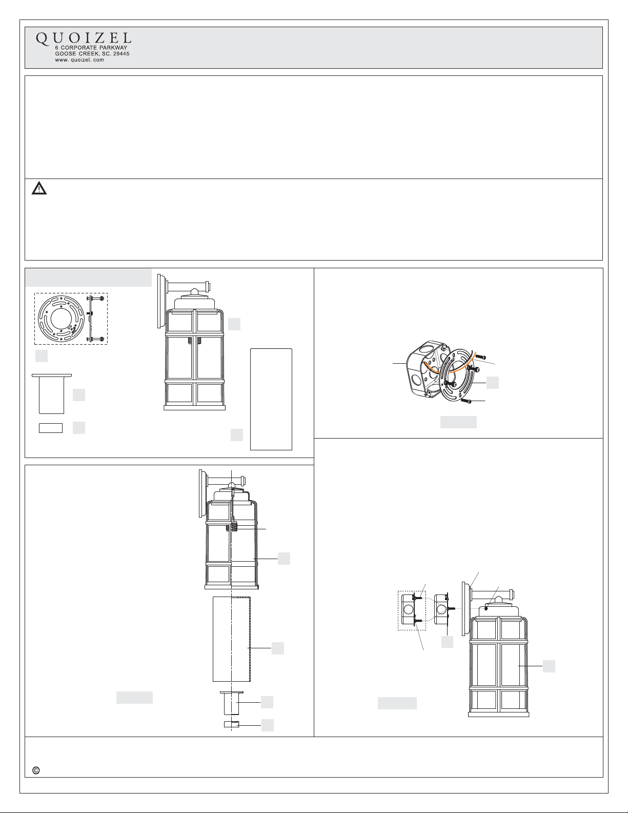
Quoizel Desoto DST8407PN Mounting instructions
Other Quoizel Outdoor Light manuals

Quoizel
Quoizel MHE8410K Mounting instructions

Quoizel
Quoizel GLS8406EK User manual

Quoizel
Quoizel SNN8406K Mounting instructions

Quoizel
Quoizel CHI9011IB User manual

Quoizel
Quoizel NY8315P Mounting instructions

Quoizel
Quoizel NY8316K Mounting instructions

Quoizel
Quoizel Style CCR8406CU Mounting instructions

Quoizel
Quoizel LTE8407PN Mounting instructions

Quoizel
Quoizel BDS8410AGV User manual

Quoizel
Quoizel WWD8409IB User manual

Quoizel
Quoizel MBH8409W User manual

Quoizel
Quoizel MHE8409K User manual

Quoizel
Quoizel DNM8410EK User manual

Quoizel
Quoizel ASH28858A0 User manual

Quoizel
Quoizel Granby GRB9008EK User manual

Quoizel
Quoizel RCE8405EK User manual

Quoizel
Quoizel SNNL9009K Mounting instructions

Quoizel
Quoizel MOI9008EK User manual

Quoizel
Quoizel Westover Outdoor WVR9007IZ User manual

Quoizel
Quoizel Waterville WTE8411WT Mounting instructions


Popular Outdoor Light manuals by other brands


HEPER
HEPER DOGO Side LW6048.585-US Installation & maintenance instructions

Maretti
Maretti VIBE S 14.6080.04.A quick start guide

BEGA
BEGA 84 253 Installation and technical information

HEPER
HEPER LW8034.003-US Installation & maintenance instructions

HEPER
HEPER MINIMO Installation & maintenance instructions

LIGMAN
LIGMAN BAMBOO 3 installation manual

Maretti
Maretti TUBE CUBE WALL 14.4998.04 quick start guide

Maxim Lighting
Maxim Lighting Carriage House VX 40428WGOB installation instructions

urban ambiance
urban ambiance UQL1273 installation instructions

TotalPond
TotalPond 52238 instruction manual

Donner & Blitzen
Donner & Blitzen 0-02661479-2 owner's manual

LIGMAN
LIGMAN DE-20023 installation manual