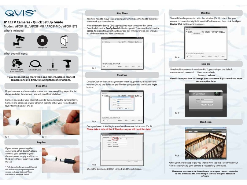
Qvis AHD-P400-4X User manual

© Copyright Qvis ®. All documentation rights reserved. 1
AHD MINI PTZ CAMERA
AHD-P400-4X
V 1.0 08.2015
QUICK INSTALLATION GUIDE

© Copyright Qvis ®. All documentation rights reserved. 2

© Copyright Qvis ®. All documentation rights reserved. 3
Welcome
Thank you for purchasing the 1080P AHD Mini PTZ Camera.
This user’s manual is designed to be a reference tool for the
installation and operation of your system.
Here you can find information about the corresponding AHD
camera’s features and functions, as well as a detailed installation
method.
Before installation and operation please read the following
safeguards and warnings carefully!

© Copyright Qvis ®. All documentation rights reserved. 4
PRECAUTIONS
1.Electrical safety
All installation and operation here should conform to your local electrical
safety codes.
The power supply shall conform to the requirement in the SELV (Safety
Extra Low Voltage) and must make sure that the limited power source is
rated 12V DC or 24V AC.
Please note: Do not connect two power supplying sources to the
device at the same time; it may result in device damage!
We assume no liability or responsibility for all the fires or electrical shock
caused by improper handling or installation.
We are not liable for any problems caused by unauthorized modification or
attempted repair.
2.Transportation Security
Please ensure that the product does not endure heavy stresses, violent
vibration or contact with water during transportation, storage and
installation.
Please use the original packing material (or the material of the same
quality) if you need to return it to vendor.
3.Installation
Do not apply power to the product before completing installation.
Do not put object(s) on the product.
Please install a proper power cut-off device during the installation
connection.
4.Qualified engineers needed
All the examination and repair work should be done by the qualified service
engineers. We are not liable for any problems caused by unauthorised
modifications or attempted repair.

© Copyright Qvis ®. All documentation rights reserved. 5
5. Environment
This product should be installed in a cool, dry place away from direct
sunlight, inflammable, explosive substances and etc.
Please keep it away from environments that contain electromagnetic
radiation or objects that produce it.
Please keep sound ventilation around the device at all times.
Do not allow the water and other liquid to penetrate into the device if
casing has been compromised. This series product complies with the IP66
standard specified in the Degrees of Protection Provided by Enclosure.
Ensure lightning surge protection is in place to make sure you fully protect
camera circuitry from electrical overload.
Please make sure the CCD (CMOS) component is away from the radiation
of the laser beam device. Otherwise it may result in CCD (CMOS) optical
component damage.
It is recommended that the grounding studs of the product should be
grounded, so to further enhance the reliability of the camera.
Avoid shooting very bright objects directly into the camera’s CCD (such as
the sun or light fittings), and avoid fixating the camera lens on bright static
object for long time, as it will cause Irreparable damage to the camera’s
CCD.
6. Daily Maintenance
Please shut down the device and then unplug the power cable before you
begin any maintenance work.
Do not touch the CCD (CMOS) optic component. Please use an air jet to
clean the dust off the lens surface. You can use the dry cloth with some
alcohol or mild detergent to clear if necessary.
When the camera is not in use please put the dustproof cap to protect the
CCD (CMOS) component.
Do not use volatile solvent such as the benzene, paint thinner or detergent
with the ability to abrade surfaces. It may result in lens damage or
adversely affect the device’s performance.
7. Accessories
Always use all the accessories recommended by manufacturer.
Before installation, please open the package and check that all the
components are included. Contact your local retailer/vendor ASAP if
something is missing.
© Copyright Qvis ®. All documentation rights reserved. 6
Contents
1. Structure...............................................................................7
1.1Multiple-function Combination Cable .......................................7
1.2Camera Diagram & Dimensions...............................................7
2Device Installation .................................................................9
3Settings for AHD PTZ Camera ............................................10
3.1Setting methods for Camera..................................................10
3.2Settings with VK200 PTZ Control Software............................ 11
3.3Set up camera through the AHD PTZ Configuration Tool.......12
3.4Set up through the preset command (Using PTZ keyboard) ..13

© Copyright Qvis ®. All documentation rights reserved. 7
1. Structure
1.1 Multiple-function Combination Cable
You can refer to the following figure for the multiple-function combination cable
information. See Figure 1-1.
Functions of external connector:
No.
Interface
Description
1
Video
AHD High Definition Video
2
Power
Power , 12V/2A DC
3
485
485 controller, Orange 485A, Yellow
485B
Sheet 1-1 Cable Function Instruction
1.2 Camera Diagram & Dimensions
(Unit: mm)
Picture 1-2 Cables

© Copyright Qvis ®. All documentation rights reserved. 8
Picture 1-3 Dimensions
Picture 1-4 Dimensions

© Copyright Qvis ®. All documentation rights reserved. 9
2 Device Installation
Picture 2-1 Bracket installation
This camera can be installed on to a vertical wall, please refer to the following
steps on how to do this:
The installation surface/wall must withstand and hold at least three times the
weight of the bracket and camera.
Step 1: Install camera bracket to camera
For cement wall:
1. Insert the expansion bolts into the bracket holes at the camera end of
the bracket
2. Feed camera’s network, power, and 485 controller cables through the
hollow part of the bracket.
3. Use the cross-head screwdriver to fix the adjust screws firmly into the
base of the camera device.
For installing camera to a wood based surface, you do not need to install
expansion bolts, use cross-head screwdriver to fix firmly.
Step 2: Install camera and bracket to wall

© Copyright Qvis ®. All documentation rights reserved. 10
Insert the expansion bolts into the installation holes. Take the screws from the
accessories bag and then use them to secure the camera device on to the
installation surface of the wall or the ceiling (prepare surface before screwing
in camera and bracket).
Step3: Use the cross-head screwdriver to fix the screws, confirm camera
has been installed firmly to bracket.
Step 4: Use a keyboard or the DVR to control the camera and adjust the
direction of where the camera is pointing to.
Warnings:
Please do not adjust camera’s casing/housing manually, it may damage
the device.
After installation, please take care you do not damage or compromise the
waterproof casing of the device. Ensure that water cannot go along the
extension line and then in to the camera’s housing causing damage to
the electrical components.
3 Settings for AHD PTZ Camera
3.1 Setting methods for Camera
AHD PTZ camera supports two kinds of control method; RS485 and UTC. If
you are using RS485 control mode, the user need to set address and baud
rate of camera. For RS485 control mode, the control protocol is self-adapting,
but the address and baud rate need to be adjusted by users. The default
address is 1and the default baud rate is 2400. Its setup method is different
from the traditional dial-number switch, the PTZ camera does not support it, so
the users need to set the camera up correctly using the following methods :
1. VK200 Control Software (see page 11 for instructions)
2. AHD PTZ Camera Configuration Tool (see page 12 for instructions)
3. Special preset commands (see page 13 for instructions)

© Copyright Qvis ®. All documentation rights reserved. 11
3.2 Settings with VK200 PTZ Control Software
VK200 is a PTZ camera controlling software which works on the computer with
a WINDOWS system. Through the RS485 adaptor (used for connecting
cameras to computers), users can control the camera, adjust addresses and
the baud rate conveniently.
The interface of the software is shown below, see picture 3-1
Picture 3-1
1. Change the PTZ camera’s address and baud rate settings using the VK200
controlling software so that it is in accordance with the settings of the PTZ
camera. Use the VK200 software to test to see if settings are correct by
seeing if the user can control camera’s movements.
2. Click ‘Search’(highlighted by the red box in Picture 3-2). The’Dome ID’
and soft address of the PTZ camera, which is connected via the RS485
cable, will show in the list. Click the ID number in the list, the corresponding
ID and address will show in the edit box. Modify the address, then click
‘add’, and the modified address will be updated within the list.

© Copyright Qvis ®. All documentation rights reserved. 12
3. Click ‘Set’; the address will be modified. If set up is successful the PTZ
camera will rotate in a vertical direction, to indicate set up was success.
Picture 3-2
Note:
If the 485 cable is only connected to one PTZ camera, then it is
convenient for user to setup camera. The user can just input 0000000000
in to the ‘Dome ID’box.
3.3 Set up camera through the AHD PTZ Configuration Tool
The PTZ camera configuration tool is shown in picture 3-3. The PTZ camera
needs to be connected to the computer using an RS485 adaptor. In the
address and baud rate edit box, the user needs to input the address and baud
rate of camera in order for it all to be set. Click ‘Set’to complete setup.

© Copyright Qvis ®. All documentation rights reserved. 13
Picture 3-3 Set up through Specific Preset Commands
Connect the PTZ camera to a controlling device such as a PTZ control
keyboard or to the DVR and adjust the corresponding address and baud rate.
The use the keyboard or DVR to test to make sure users can control the device
normally.
Caution:
After setting up the address and baud rate of camera, if the format of the
video does not match with the one in the DVR or other controlling
devices, then images may not be shown on the screen.
3.4 Set up through the preset command (Using PTZ keyboard)
Function
Command
Instruction
Address
Set 85, Call 60, Call n
n: PTZ camera address
Baud rate
Set 85, Call 61, Call n
n:1.2400
2.4800
3.9600
Video
Set 85, Call 62, Call n
n: 1.AHD PAL
2. AHD NTSC
4. CVBS PAL
5. CVBS NTSC
Guard Function
Set 85,Call 75, Call n
n: 1. Close guard
function
2. Preset 1
3. Auto-scan 1

© Copyright Qvis ®. All documentation rights reserved. 14
4. Sequence 1
5. Pattern 1
Guard Function Time
Set 85, Call 76, Call n
n: 1-60 Min
IR Mode
Set 85, Call 70, Call n
n: 1. Auto
2. Open
3. Close
IR Near Power
Set 85, Call 71, Call n
n: 1-10
IR Far Power
Set 85, Call 72, Call n
n:1-10
IR Sensitivity
Set 85, Call 73, Call n
n: 1-10
the smaller the value,
the lower the illumination
amount
Scan Left border
Set 92
Scan Right border
Set 93
Scan Speed
Set 85, Call 77, Call n
n: 1-50
Scan Start
Call 99
Scan Stop
Call 96
Sequence Starting Point
Set 85, Call 50, Call n
n: Sequence Starting
Preset
Sequence Stopping
Point
Set 85, Call 51, Call n
n: Sequence Stopping
Preset
Sequence Preset
Parking Time
Set 85, Call 52, Call n
n: 1-255 sec
Sequence Start
Call 98
Sequence Stop
Call 96
Pattern Setting Start
Set 86
Pattern Setting Stop
Call 96
Pattern Start
Call 97
Pattern Stop
Call 96
Open Menu
Call 95
Notes:
1. If the video format’s set up cannot match the display device or DVR
capabilities, it may lead to the camera’s image not being shown.
2. Sequence default includes preset 1-preset 10, parking time is 10sec.

© Copyright Qvis ®. All documentation rights reserved. 15
For more information about our AHD Cameras and other
available CCTV cameras, NVRs & accessories, please
visit our website:
www.adata.co.uk
Alternatively scan this QR code with your smart phone to
be directed instantly to our website:
Table of contents
Other Qvis Security Camera manuals

Qvis
Qvis MINI-PTZ-23X-H User manual

Qvis
Qvis IPTZ-IR20A User manual

Qvis
Qvis APOIP-MB User manual

Qvis
Qvis EYE-4MP-FG/W Instruction manual

Qvis
Qvis AMB-VANIR User manual

Qvis
Qvis APOIR-PTZ23 User manual

Qvis
Qvis IPTZ-P400-10X User manual

Qvis
Qvis KIT005-SFX User manual

Qvis
Qvis APOHD-PTZ20 User manual

Qvis
Qvis APOIP-BL User manual