Qvis KIT005-SFX User manual

FACE DETECTION FUNCTION SETUP
Mounting Angle of Camera
30° 30°
Cameras Distance and Lens Focal Length
8% 20% 100%
L-max
L-better
1
.
2
.
3.
Software Setup
To complete the facial detection setup you will need to switch on
the the DVR and set the detection areas (the rst thing you may
see on the monitor screen will be the P2P Setup Wizard, please turn
over for the instructions for this). Follow the steps below:
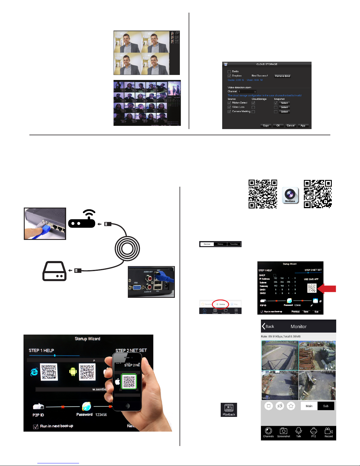
Continued next page
Enter main menu (right click)
• Face: to set face detection
parameters
• Face Search: to search face
images and video data stored on
the DVR.
• Storage: to set cloud storage
function (save face snapshots
remotely).
Face - setting the detection area
Enter main menu and set face
detection parameters.
Red: Detection area
Once set, the device only detects
the faces in the detection area.
False positives and underreporting
can be effectively reduced by
setting the detection area correctly.
Blue: Minimum face
This means the minimum face
detection area. When the face is
smaller than minimum detection
area, it cannot be detected.
Yellow: Maximum face
This means the maximum face
detection area. When the face is
more than the maximum detection
area, it cannot be detected.
BNC Connector
Power Connector
Camera
Output to TV
or Monitor
BNC Connecto r
to DVR
Power Adaptor
4-Way Split Cable
Power
Connecto r
BEFORE INSTALLING ANYTHING WE
STRONGLY RECOMMEND THAT YOU
CONNECT YOUR CAMERAS TO YOUR DVR
AND TEST YOUR SYSTEM FIRST.
WE CHECK EVERYTHING TO MAKE SURE IT
IS WORKING WHEN IT LEAVES US BUT
OCCASIONALLY THINGS FAIL AND IT IS
BETTER TO KNOW NOW THAN AFTER YOU
HAVE FITTED EVERYTHING!
QUICK SET UP
GUIDE
This connects
your camera to
the DVR
This connects
your camera to
the power supply
Connect the
mouse to the
USB socket
(We recommend you
keep your cables
coiled whilst you test
your system)
1.
2.
3.
Connecting your cameras.
Your Cameras have 2 plugs
attached, one is a BNC connector
(for the video) the other is for
power. Connect these plugs into
the sockets on the end of one of
the cables included in the kit.
1.
Switch on
Once you have connected all the
cables successfully connect the
DVR & Camera power leads to a
power outlet. Switch on your TV
and select the HDMI socket you
have DVR connected to.
3.
Connecting your DVR.
At the other end of the cable there
are two plugs, these connect your
camera to the DVR and also to the
power supply.
.
2.
DVR Power
You can connect your system to
a HD TV using a HDMI Cable, you
can also connect them together
using an RCA lead, or to a
monitor using a VGA lead.
The face detection feature can tolerate an angle error of up to 45
degrees. Clear facial images will decrease the chance of an omission
from the face capture list.
Horizontal Angle Vertical Angle
The horizontal angle is the angle
between the camera and the
horizontal direction away from
the face pointing at the camera.
The limit should be below 45
degrees. It is recommended not
to exceed 30 degrees.
The vertical angle means the
angle above and between
camera and person’s face.
The limit should be below 45
degrees. It is recommended not
to exceed 30 degrees.
The proportion of the face
inside the screen is a critical
factor for face detection. The
minimum height of the face
should be more than 8% of the
screen and the recommended
height is 20% of the screen.
Baring in mind the above
requirements, you can gure out
how to choose the lens according
to the size of the camera’s
sensor.
You will also need to connect yout
DVR to a TV or monitor. You can
connect your system to a HD TV using
a HDMI cable, you can also use the
RCA (Video Out) socket or the VGA
socket on the back of the DVR.
Further, more detailed instructions on how to operate your DVR are included in the main manual which is on the set up disc included.
We refrain from printing these large manuals in an effort to limit our impact on the environment.
KIT005-SFX
KIT006-SFX
CAM005

FACE DETECTION FUNCTION
SETUP (Cont.)
Return to the real-time monitoring
page using the right click on
the mouse. Face images will be
presented on the right hand side of
real-time monitoring screen. The face
picture will be saved to the DVR’s
HDD.
Enter the Face search page, you
will be able to search the recorded
face list. By double clicking the face
pictures you will be able to play back
the video footage from the time
around when the face was recorded.
Face Search List
EASY SMART PHONE SETUP FOR LIVE VIEW & REMOTE PLAYBACK
Success! You should now be fully setup.
The device can upload face pictures automatically to a cloud
storage account by syncing to your Dropbox account.
From the Main Menu, select Cloud Storage and setup the link
between the DVR and your Dropbox account. You can choose
what video source you would like to be backed up remotely.
Choose between Motion Detect, Video Loss & Camera Masking.
CLOUD STORAGE BACKUP
For the convenience of monitoring your Qvis security system on the move via your smart phone we have provided a quick and simple remote
connection setup service. Please follow the steps below closely to successfully setup the connection for live view and remote playback.
3.
1.
PLEASE MAKE SURE THAT YOUR DVR DEVICE IS SETUP AS SHOWN ON THE REVERSE SIDE OF THIS PAGE BEFORE CONTINUING.
Internet connection
Connect the Ethernet cable into the ‘Net’ port on the rear of
the device, then connect the other end into one of the spare
ports on your modem-router, as shown below.
Ethernet connector
to DVR ‘NET’ port
Ethernet connector
to spare router port
Ethernet
cable
Modem - Router
Download & install
Medusa app
Select the Medusa
app and install on to
your smart phone
2. Step 1: Download Sentient 960H app
Turn the power on to the DVR device. When it has fully
booted up, you will be presented with a ‘Startup Wizard’
window displayed on your monitor.
www.qviscloud.co.uk Android App
For more help please visit www.sentientconnect.co.uk
www.sentientconnect.co.uk Android App iOS App
For more help please visit www.sentientconnect.co.uk
Using a QR scan app, scan the corresponding QR code to the
operating system on your phone, i.e. scan the iOS QR code if you
have an iPhone.
4.Add new device
Once installed, open
it up and press the
button: ‘+ Device’.
Scan unique device QR code
The next screen will have an
icon of a QR code, select this
to use the inbuilt QR scanner.
Scan QR code found on Step
2 of the Startup Wizard,
shown on your monitor
screen.
5.
Scan
here
6. View Live feed cameras
Your DVR will now be
shown on the list of
devices along with a list of
camera channels.
The video channel display
screen will then allow
you to view the cameras
connected to the DVR.
Playback
To playback and review
footage select the icon
shown here found on the
device list screen:
Choose the date, time
and channel you wish to
view footage from and
then the app will search
for recorded footage to
review.
ANDROID APP iOS (APPLE) APP
For further info or help with your product, please visit: www.qvishome.co.uk

© Copyright QVIS Home ®. All documentation rights reserved.
i
4/8/16 Channel 960H DVR
USER’S MANUAL
V2.0 01.2015

© Copyright QVIS Home ®. All documentation rights reserved.
ii
Welcome
Thank you for purchasing our 960H CCTV DVR/kit.
This user’s manual is designed to be a reference tool for
the operation of your system.
Do not worry; you do not have to read this entire
manual to be up and running. There should be a
quickstart guide found with your DVR device, which will
show you how to setup the connections to the DVR
correctly and how to setup a remote monitoring
connection.
Here you can find information about the corresponding
DVR’s features and functions, as well as a detailed menu
tree.
Before installation and operation please read the
following safeguards and warnings carefully!

© Copyright QVIS Home ®. All documentation rights reserved.
iii
BEFORE YOU BEGIN
Important Safeguards and Warnings
1.Electrical safety
All installation and operation should conform to your local electrical
safety codes.
We assume no liability or responsibility for any fires or electrical
shock caused by improper handling or installation.
2.Transportation security
Heavy stress, violent vibration or water splash should be avoided
during transportation, storage and installation.
3.Installation
Keep upright. Handle with care.
Do not apply power to the DVR before completing installation.
Do not place objects on top of the DVR
4.Qualified engineers needed
All examination and repair work should be done by qualified service
engineers.
We are not liable for any problems caused by unauthorised
modifications or attempted repair.
5.Environment
The DVR should be installed in a cool, dry place away from direct
sunlight and inflammable or explosive substances, etc.
This product should be transported, stored and operated in an
environment ranging from 0℃to 55 ℃.
6. Accessories
Be sure to use all the accessories available in the Qvis Home range.
Before installation, please open the package and check all the
components are included.
Contact your local Maplin outlet if something is broken or missing in
your package.
7. Lithium battery
Improper battery use may result in fire, explosion, or personal injury.
When replacing the battery, please make sure you use the same
model. (CR2032 Motherboard battery).

© Copyright QVIS Home ®. All documentation rights reserved.
iv
TABLE OF CONTENTS
1 FEATURES AND QUICK SETUP........................................................................1
1.1 Product Overview ........................................................................................................................................1
1.2 Features..........................................................................................................................................................1
1.3 Installation ....................................................................................................................................................2
1.3.1 Unpacking Inspection..............................................................................................................................2
1.3.2 Wiring Installation ....................................................................................................................................2
1.4 Quick Setup Diagram............................................................................................................................... 4
1.5 Smart Phone Setup for Live View & Remote Playback................................................................ 4
1.6 The Mouse ....................................................................................................................................................5
1.7 On-screen keyboard................................................................................................................................. 6
1.8 Power On/Off............................................................................................................................................. 6
1.8.1 Power On ......................................................................................................................................................6
1.8.2 Power Off.....................................................................................................................................................8
1.8.3 Power recovery.........................................................................................................................................8
1.9 Icon ................................................................................................................................................................ 8
1.9.1 Icons................................................................................................................................................................8
1.9.2 Operation Icons ........................................................................................................................................9
1.10 The Real-time Browser.......................................................................................................................... 9
2 OPERATIONS GUIDE................................................................................................ 10
2.1 The Right-click Menu ..............................................................................................................................10
2.1.1 The Screen Switching............................................................................................................................10
2.1.2 Color setting ............................................................................................................................................. 10
2.1.3 The Video Inquiry.................................................................................................................................... 11
2.1.4 Alarm output............................................................................................................................................. 11
2.1.5 The Main Menu......................................................................................................................................... 12
2.2 The Introduction of the Main Menu ................................................................................................... 13
2.3 The Video Inquiry.................................................................................................................................... 13
2.4 Configuration............................................................................................................................................ 17
2.4.1 System ........................................................................................................................................................ 17
2.4.2 Record ....................................................................................................................................................... 18
2.4.3 Network..................................................................................................................................................... 21

© Copyright QVIS Home ®. All documentation rights reserved.
v
2.4.4 Alarm......................................................................................................................................................... 23
2.4.5 Account.................................................................................................................................................... 24
2.4.6 Abnormity ............................................................................................................................................... 25
2.5 Storage ...................................................................................................................................................... 26
2.5.1 HDD Management................................................................................................................................. 26
2.5.2 Backup ...................................................................................................................................................... 27
2.6 Output........................................................................................................................................................ 28
2.6.1 Display ....................................................................................................................................................... 29
2.7 Maintain ...................................................................................................................................................... 31
2.7.1 Log................................................................................................................................................................ 31
2.7.2 Version ...................................................................................................................................................... 32
2.7.3 Default....................................................................................................................................................... 32
2.7.4 BPS ............................................................................................................................................................. 33
2.7.5 Auto Maintain......................................................................................................................................... 33
2.7.6 Online User.............................................................................................................................................. 33
2.8 Shutdown.................................................................................................................................................. 33
3 WEB AND CLIENT ................................................................................................... 34
3.1 Web Operation ........................................................................................................................................34
3.1.1 Network Connection............................................................................................................................. 34
3.1.2 The Interface Of Web Operations.................................................................................................. 35
3.1.3 The Real-time Monitoring .................................................................................................................. 36
3.1.4 Configuration .......................................................................................................................................... 37
3.1.5 Search Record ........................................................................................................................................ 38
3.1.6 Alarm Configuration ............................................................................................................................ 39
4 TROUBLESHOOTING..............................................................................................40

© Copyright QVIS Home ®. All documentation rights reserved.
1
1 FEATURES AND QUICK SETUP
1.1 Product Overview
This product is designed specifically for the use in the field of video surveillance and
adopts H.264 video compression, hard disk recording, TCP/IP transmission and a Linux
based OS in addition to some of the most advanced technology in the information
technology industry. These elements help to produce a more stable, reliable and higher
quality video image. The products support synchronised video, audio recording,
playback, monitoring and the synchronisation of audio and video. The products support
advanced control technology and strong network data transmission capacity.
1.2 Features
Real-time monitoring
Composite video signal interface and support TV, VGA or HDMI output simultaneously.
Compression function
Uses H.264 video compression standard and G.711 audio compression standard and
has high definition, low code rate of the video coding to decrease the amount of data to
save to HDD storage.
Recording function
Supports timing, alarm alerts, motion detection, SATAhard and local hard disks, DVR
data backup and network backup.
Video playback function
You can search videos, within the local network, by using the playback interface. As well
as this it supports multiple videos playback, fast playing, slow playing and frame-by-
frame playback. Video playback can be displayed the exact time of the incident using a
graphical timeline to allow you to search for event footage much more efficiently.
Camera control and alarm
Remotely installed cameras can be controlled and various alarm devices can be
connected to ensure that you know when an event has been detected. The DVR
integrates Dynamic detection, video loss, video block, multiple alarm output and scene
lighting control into its controller options.
Communication Interface
Equiped with USB 2.0 high-speed interface and an ESATAinterface to allow for external
video backup devices. There is also an option to store data on a remote server (cloud
storage location) by connected the DVR to a local or wide area network by using the
standard Ethernet interface port (plug and play).

© Copyright QVIS Home ®. All documentation rights reserved.
2
Network functions
Supports:
TCP / IP
UDP
RTP / RTSP
DHCP
PPPOE
DDNS
NTP
Also supports real-time network monitoring, video playback, control and management
functions. The built-in WEB Server will allow you to directly access the DVR through a
web browser.
Mode of operation
You can operate by the DVR’s front panel or using a mouse. A simple, intuitive graphical
interface is provided for intuitive operation.
1.3 Installation
1.3.1 Unpacking Inspection
When you receive the product pleae check that all items are present according to the
packing list on the reverse of the box.
1.3.2 Wiring Installation
Prepare for installation
Prepare your cameras, TV/display monitor, video cables, network cables, the mouse,
and power cables on a large clean flat surface.
Installation Steps:
(See quick startup guide page 4)
NOTE: Before installing anything we strongly recommend that you connect
your cameras to your dvr and test your system first.

© Copyright QVIS Home ®. All documentation rights reserved.
3
NOTE: WE CHECK EVERYTHING TO MAKE SURE IT IS WORKING WHEN IT
LEAVES US BUT OCCASIONALLY THINGS FAIL AND IT IS BETTER TO KNOW
NOW THAN AFTER YOU HAVE FITTED EVERYTHING!
1. Place the DVR on a flat horizontal position and connect your cameras to the
video input on the rear of the DVR.
2. Connect your TV/ display monitor to the video output on the rear of the DVR.
3. Connect the network cable to the RJ45 socket on the rear of the DVR then
connect the other end of the cable to a spare socket on the router.
4. Connect the Mouse to the USB interface found in either the front or rear panels.
5. Connect your DVR a power outlet and switch on the power.
Caution
For an external alarm device or a PTZ, please refer to the relevant instructions.
Connect the power line after all lines connected correctly.

© Copyright QVIS Home ®. All documentation rights reserved.
4
1.4 Quick Setup Diagram
1.5 Smart Phone Setup for Live View & Remote Playback
For the convenience of monitoring your Qvis Home security system on the move via
your smart phone we have provided a quick and simple remote connection setup
service. Please follow the steps below closely to successfully setup the connection for
live view and remote playback. See next page for step-by-step setup instructions.

© Copyright QVIS Home ®. All documentation rights reserved.
5
1.6 The Mouse
The mouse is used to operate all aspects DVR.
Right mouse click is used to:
Open up a new menu in the real-time monitoring screen.
Exit the current screen without saving.
Left click is used to:
Enter the desired menu or the main screen.
Select menu options.
Select/unselect the checkboxes.
When controlling a PTZ camera.

© Copyright QVIS Home ®. All documentation rights reserved.
6
Double Click is used to:
Play video.
Make selected camera full screen or to exit full screen mode.
Scrolling wheel is used to:
Control the zoom function of the PTZ cameras.
Mouse Drag can be used to select:
Area for facial detection.
Areas to block (for motion detection).
Select zooming function of PTZ control.
1.7 On-screen keyboard
The onscreen keyboard is operated via the mouse’s left click. To enter passwords,
usernames, values, etc.
Shift = Caps on/Caps off
Left pointing arrow = Left/delete
= Space between characters
1.8 Power On/Off
1.8.1 Power On
Install the DVR correctly (as above) and then connect the power. The DVR LED should
light up light up and the DVR will boot automatically.
The DVR will then automatically detect any connected hardware (cameras, monitors,
etc.), this process should last about 20 Seconds. When this process has been
completed the DVR will enter the multi-screen real-time surveillance mode.
If your hard drive is not properly connected, the following message will appear on your
screen.

© Copyright QVIS Home ®. All documentation rights reserved.
7
Below is the multi-screen real-time surveillance mode:
NOTE: Please do not use any type of power supply which is different from
the power supply included in this kit.

© Copyright QVIS Home ®. All documentation rights reserved.
8
1.8.2 Power Off
Right mouse click →【Main Menu】→【Shutdown】
NOTE: Only change or attempt to reconnect the hard disk drive after shutting
down the DVR.
1.8.3 Power recovery
After an unexpected power shortage or forced shutdown the DVR will save any footage
recorded before the power outage and should return to the normal operation mode
once it has restarted.
1.9 Icon
1.9.1 Icons
:The channel is recording.
:The video feed of the channel has been lost.
:Motion detection functionality is on.
:The channel is currently in monitoring and locked status.
:Adjust the volume of audio output.
:Slideshow of all connected cameras, in full screen.

© Copyright QVIS Home ®. All documentation rights reserved.
9
1.9.2 Operation Icons
: Not selected.
: Selected.
: The drop - down button
:Leave the interface.
:Cancel the settings.
:Set parameters.
:Save parameters
:Restore the factory settings.
:Apply current settings to the system.
:Copy current settings to other channels.
:Enter the configuration interface.
:Select and configure the processing operation triggered by video
detection or alarm.
1.10 The Real-time Browser
There are date, channel name, record icon and alarm status icon in each real-time
monitoring screen. Switch screens by the front panel, a remote control or a mouse.
If screen prompts of external alarm, video loss, occlusion detection, dynamic detection,
network connection and IP conflict is set, the following interface will pop up when the
relevant alarm occurs.

© Copyright QVIS Home ®. All documentation rights reserved.
10
2 OPERATIONS GUIDE
2.1 The Right-click Menu
Enter the real-time channel browsing interface. Click the right button on the mouse to
bring up the pop-up menu as shown in the figure below.
The Right button menu:
2.1.1 The Screen Switching
Users can choose to have either single, four, nine or sixteen channels.
2.1.2 Color setting
If you need to set a certain colour level configuration on the channel browsing display
interface for a certain time of day (e.g. one configuration for the daytime and another
configuration for the night time), you can set this up via the ‘Colour Setting’ menu found
on the right-click menu. You can set two time periods for two seperate colour
configurations that suit the lighting environment around where you view the footage
from the cameras on the display monitor.
Image color hue, brightness, contrast, saturation, gain and white-level parameters can
all be adjusted to desired levels. See screen shot of the Colour Setting menu on the
next page.

© Copyright QVIS Home ®. All documentation rights reserved.
11
【Period】: Two periods can be set according to ambient light during the day and night,
device will automatically switch configuration time. Need to select the Enable box.
【Hue】: Adjust the image color cast.
【Brightness】: Visual image brightness (according to the environment), reduces or
increases the brightness of the image to try to make it clearer.
【Contrast】: Adjusts the black and white colours of the image (the greater the ratio,
the brighter the image).
【Saturation】: Image color purity. The greater the value the more colourful the
images will become.
NOTE: Different mode different function
2.1.3 The Video Inquiry
Refer to Chapter 2.3.
2.1.4 Alarm output
NOTE: only users who have the highest priority setting on their profile can
use the manual recording function.
In the real-time monitoring screen, right click and select ‘Record’ to enter the following
interface.

© Copyright QVIS Home ®. All documentation rights reserved.
12
【Channels】The number of channels that are in alarm status mode.
【Schedule】Alarm output are in control of the alarm configuration.
【Manual】Alarm output is on and the status is active.
【Stop】Alarm output is off and the status is inactive.
【Status】The current status of alarm output.
2.1.5 The Main Menu
Left click in the real-time monitoring screen. Input a user name and a password.
Default users:
User Type
Name
Default Password
Administrator
admin
123456
User
user
123456
Hidden
default
default
NOTE: security measures of the password: If you input the wrong password
three times, the device will produce an alarm sound. After incorrectly inputting
the password in five times, the account will be locked. Please change the default
password and the user name. Refer to Chapter 2.4.5 ‘Accounts’ for more details.

© Copyright QVIS Home ®. All documentation rights reserved.
13
2.2 The Introduction of the Main Menu
【Search】Search recorded footage by types, channels, time and playback records.
【Configuration】Includes; system, record, network, abnormity, alarm, account.
【Storage】HDD management and backup
【Output】Options include: PTZ, alarm output, serial and display.
【Maintain】Displays; log information, version information, stream statistics, online
users, sets the factory default & automatic maintenance.
【Shutdown】Log off from the user menu, turn off the machine, restart the system,
and switch user and other operations.
2.3 The Video Inquiry
In the real-time monitoring screen, right click and select【search】to enter the search
interface.
Other manuals for KIT005-SFX
1
This manual suits for next models
2
Table of contents
Other Qvis Security Camera manuals

Qvis
Qvis APOIP-BL User manual

Qvis
Qvis IPTZ-P400-10X User manual

Qvis
Qvis Quattro User manual

Qvis
Qvis KIT005-SFX User manual

Qvis
Qvis AMB-VANIR User manual

Qvis
Qvis EYE-4MP-FG/W Instruction manual

Qvis
Qvis HDCVI-MB1 User manual

Qvis
Qvis IPTZ-IR20A User manual

Qvis
Qvis APOIP-EYE1.3 User manual

Qvis
Qvis MINI-PTZ-23X-H User manual