manuals.online logo
Brands
  1. Home
  2. •
  3. Brands
  4. •
  5. Radio Shack
  6. •
  7. Desktop
  8. •
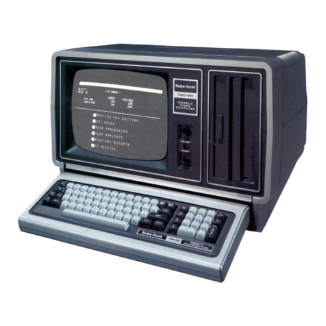
  9. Radio Shack TRS-80 DT-1 User manual

Radio Shack TRS-80 DT-1 User manual

f*\
TRS-8CT DT-1
Owner's Manual
Radio /haek
ADIVISION OF TANDY CORPORATION
FORT WORTH, TEXAS 76102
^
^
^"^s
TERMS AND CONDITIONS OF SALE AND LICENSE OF RADIO SHACK COMPUTER EQUIPMENT AND SOFTWARE
PURCHASED FROM ARADIO SHACK COMPANY-OWNED COMPUTER CENTER, RETAIL STORE OR FROM A
RADIO SHACK FRANCHISEE OR DEALER AT ITS AUTHORIZED LOCATION
CUSTOMER OBLIGATIONS LIMITED WARRANTY
A. CUSTOMER assumes full responsibility that this Radio Shack computer hardware purchased (the "Equipment"), and any copies of Radio
Shack software included with the Equipment or licensed separately (the "Software") meets the specifications, capacity, capabilities,
versatility, and other requirements of CUSTOMER.
B. CUSTOMER assumes full responsibility for the condition and effectiveness of the operating environment in which the Equipment and Software
are to function, and for its installation.
II. RADIO SHACK LIMITED WARRANTIES AND CONDITIONS OF SALE
A. For aperiod of ninety (90) calendar days from the date of the Radio Shack sales document received upon purchase of the Equipment, RADIO
SHACK warrants to the original CUSTOMER that the Equipment and the medium upon which the Software is stored is free from manufacturing
defects. THIS WARRANTY IS ONLY APPLICABLE TO PURCHASES OF RADIO SHACK EQUIPMENT BY THE ORIGINAL CUSTOMER FROM
RADIO SHACK COMPANY-OWNED COMPUTER CENTERS, RETAIL STORES AND FROM RADIO SHACK FRANCHISEES AND DEALERS AT ITS
AUTHORIZED LOCATION. The warranty is void if the Equipment's case or cabinet has been opened, or if the Equipment or Software has been
subjected to improper or abnormal use. If amanufacturing defect is discovered during the stated warranty period, the defective Equipment
must be returned to aRadio Shack Computer Center, aRadio Shack retail store, participating Radio Shack franchisee or Radio Shack dealer
for repair, along with acopy of the sales document or lease agreement. The original CUSTOMER'S sole and exclusive remedy in the event of
adefect is limited to the correction of the defect by repair, replacement, or refund of the purchase price, at RADIO SHACK'S election and sole
expense. RADIO SHACK has no obligation to replace or repair expendable items.
8. RADIO SHACK makes no warranty as to the design, capability, capacity, or suitability for use of the Software, except as provided in this
paragraph. Software is licensed on an "AS IS" basis, without warranty. The original CUSTOMER'S exclusive remedy, in the event of a
Software manufacturing defect, is its repair or replacement within thirty (30) calendar days of the date of the Radio Shack sales document
received upon license of the Software. The defective Software shall be returned to aRadio Shack Computer Center, aRadio Shack retail store,
participating Radio Shack franchisee or Radio Shack dealer along with the sales document.
C. Except as provided herein no employee, agent, franchisee, dealer or other person is authorized to give any warranties of any nature on behalf
of RADIO SHACK.
D. Except as provided herein, RADIO SHACK MAKES NO WARRANTIES, INCLUDING WARRANTIES OF MERCHANTABILITY OR FITNESS FOR A
PARTICULAR PURPOSE.
E. Some states do not allow limitations on how long an implied warranty lasts, so the above limitation(s) may not apply to CUSTOMER.
III. LIMITATION OF LIABILITY
A. EXCEPT AS PROVIDED HEREIN, RADIO SHACK SHALL HAVE NO LIABILITY OR RESPONSIBILITY TO CUSTOMER OR ANY OTHER PERSON
OR ENTITY WITH RESPECT TO ANY LIABILITY, LOSS OR DAMAGE CAUSED OR ALLEGED TO BE CAUSED DIRECTLY OR INDIRECTLY BY
"EQUIPMENT" OR "SOFTWARE" SOLD, LEASED, LICENSED OR FURNISHED BY RADIO SHACK, INCLUDING, BUT NOT LIMITED TO, ANY
INTERRUPTION OF SERVICE, LOSS OF BUSINESS OR ANTICIPATORY PROFITS OR CONSEQUENTIAL DAMAGES RESULTING FROM THE
USE OR OPERATION OF THE "EQUIPMENT" OR "SOFTWARE". IN NO EVENT SHALL RADIO SHACK BE LIABLE FOR LOSS OF PROFITS, OR
ANY INDIRECT, SPECIAL, OR CONSEQUENTIAL DAMAGES ARISING OUT OF ANY BREACH OF THIS WARRANTY OR IN ANY MANNER
ARISING OUT OF OR CONNECTED WITH THE SALE, LEASE, LICENSE, USE OR ANTICIPATED USE OF THE "EQUIPMENT" OR "SOFTWARE".
NOTWITHSTANDING THE ABOVE LIMITATIONS AND WARRANTIES, RADIO SHACK'S LIABILITY HEREUNDER FOR DAMAGES INCURRED BY
CUSTOMER OR OTHERS SHALL NOT EXCEED THE AMOUNT PAID BY CUSTOMER FOR THE PARTICULAR "EQUIPMENT" OR "SOFTWARE-
INVOLVED.
B. RADIO SHACK shall not be liable for any damages caused by delay in delivering or furnishing Equipment and/or Software.
C. No action arising out of any claimed breach of this Warranty or transactions under this Warranty may be brought more than two (2) years
after the cause of action has accrued or more than four (4) years after the date of the Radio Shack sales document for the Equipment or
Software, whichever first occurs.
D. Some states do not allow the limitation or exclusion of incidental or consequential damages, so the above limitation(s) or exclusion(s) may
not apply to CUSTOMER.
IV. RADIO SHACK SOFTWARE LICENSE
RADIO SHACK grants to CUSTOMER anon-exclusive, paid-up license to use the RADIO SHACK Software on one computer, subject to the following
provisions:
A. Except as otherwise provided in this Software License, applicable copyright laws shall apply to the Software.
B. Title to the medium on which the Software is recorded (cassette and/or diskette) or stored (ROM) is transferred to CUSTOMER, but not title to
the Software.
C. CUSTOMER may use Software on one host computer and access that Software through one or more terminals if the Software permits this
function.
D. CUSTOMER shall not use, make, manufacture, or reproduce copies of Software except for use on one computer and as is specifically
provided in this Software License. Customer is expressly prohibited from disassembling the Software.
E. CUSTOMER is permitted to make additional copies of the Software only for backup or archival purposes or if additional copies are required in
the operation of one computer with the Software, but only to the extent the Software allows abackup copy to be made. However, for
TRSDOS Software, CUSTOMER is permitted to make alimited number of additional copies for CUSTOMER'S own use.
F. CUSTOMER may resell or distribute unmodified copies of the Software provided CUSTOMER has purchased one copy of the Software for each
one sold or distributed. The provisions of this Software License shall also be applicable to third parties receiving copies of the Software from
CUSTOMER.
G. All copyright notices shall be retained on all copies of the Software.
V. APPLICABILITY OF WARRANTY
A. The terms and conditions of this Warranty are applicable as between RADIO SHACK and CUSTOMER to either asale of the Equipment and/or
Software License to CUSTOMER or to atransaction whereby RADIO SHACK sells or conveys such Equipment to athird party for lease to
CUSTOMER.
B. The limitations of liability and Warranty provisions herein shall inure to the benefit of RADIO SHACK, the author, owner and/or licensor of the
Software and any manufacturer of the Equipment sold by RADIO SHACK.
VI. STATE LAW RIGHTS
The warranties granted herein give the original CUSTOMER specific legal rights, and the original CUSTOMER may have other rights which vary
from state to state.
The FCC wants you to know,
Warning: This equipment generates, uses, and can radiate
radio frequency energy and if not installed and used in
accordance with the instructions manual, may cause
interference to radio communications. It has been tested
and has been found to comply with the limits for Class A
computing devices pursuant to Subpart Jof Part 15 of FCC
Rules, which are designed to provide reasonable protection
against such interference when operated in acommercial
environment. Operation of this equipment in aresidential
area is likely to cause interference in which case the user
at his own expense will be required to take whatever
measures may be required to correct the interference.
TRS-80® OT-1 Owner's Manual: Copyright® 1982 Tandy
Corporation, Fort Worth, Texas 76102 U. S. A.
All Rights Reserved.
Reproduction or use, without express written permission from
Tandy Corporation, of any portion of this manual is
prohibited. While reasonable efforts have been taken in the
preparation of this manual to assure its accuracy, Tandy
Corporation assumes no liability resulting from any errors
or omissions in this manual, or from the use of the
information obtained herein.
The system software in the DT-1 is retained in aread-only
memory (ROM) format. All portions of this system software,
whether in the ROM format or other source code form format,
and the ROM circuitry, are copyrighted and are the
proprietary and trade secret information of Tandy
Corporation. Use, reproduction, or publication of any
portion of this material without the prior written
authorization of Tandy Corporation is strictly prohibited.
Radio /hack
OT-l ®Owner's Manual
Contents
Introduction 5
1/ Description of the DT-1 7
2/ Setting Up the DT-1 .!3
Connecting the DtKL to aTRS-80 16
Connecting the DT-1 to aModem 19
Connecting the DT-1 to a Printer 20
3/ Using the DT-1 21
Establishing DT>1 Input/Output Parameters ("Set-Up" ). 23
Printer Operation 32
Local Made Coimands 33
4/ Troubleshooting and Maintenance 37
5/ Specifications 39
Appendix A/ The ASCII Character Set 41
Appendix B/ Table of Keyboard Codes .43
Appendix C/ Keyboard Equivalents for GDirmon Terminals 47
Ttelevideo 910 Keyboard Equivalents 48
ADDS 25 Keyboard Equivalents 50
Lear Siegler ADM-5 Keyboard Equivalents 52
Hazeltine 1410 Keyboard Equivalents 54
Appendix D/ Glossary 57
Appendix E/ Cursor Position Coordinates 61
i^pendix F/ Control Codes for Video Display 63
Radio /hack
-3-
OT_1 ____ _<s> Owner's Manual
TRS-SO ®
Radio /hack
DT-1 -^—.(R Owner's Manual
—TRS-BO @
Introduction
What is adata terminal?
Terminus: Lat. Boundary or End,
Adata terminal is the connection between you and a
corrputer. It is not aconputer. It is aconnection to a
computer and transfers information from human form (e.g.,
letters, numbers, etc.) to aformat computers understand
(e.g., electrical pulses)*
There are three parts to aTerminal:
The Keyboard, where you enter data.
The Video Screen, where the Computer outputs data in
visible form.
The Input/Output Channels, where the Terminal
communicates with the Computer.
When you connect aData Terminal to apower source and turn
the switch ON, nothing really happens unless the Terminal is
connected to a"Host" computer. AHost is the controlling
coirputer in amultiple-conputer system. Consequently, the
operation and capabilities of your Data Terminal are limited
only by the limitations of the Host coirputer —your
Terminal can only do what the Host can do and no more!
Ebr instance, your Data Terminal cannot store programs or
data itself, but it can access information stored by the
Host System.
Note that different Host Systems operate in different ways.
In fact, they may even recognize different keyboards. If you
press akey on the Terminal when it is connected to one
Host, the reaction may be totally different than when you
press the sane Terminal key when it is connected to a
different Host!
In other words, the specific operation of your Data
Tterminal depends upon the Host that is in control.
Consequently, good Data Terminals (like the DT-1) must be
designed to operate with avariety of different Hosts.
—Radio /hack
_c; _
DT-1 TRS-BO @Owner's Manual
Where is the Host conputer?
The Host conputer may be located near the DT-1 (directly
connected), or it may be hundreds of miles away and
connected to your Terminal via modems and telephone lines.
Can aDT-1 ooraoinicate with another OT-1?
Yes, two DT-l's can coimrunicate (e.g., you and another OT-1
user can "talk" by typing on the keyboard) but that's all
they can do. They can't process or store any information
unless they're connected to aHost.
Other special features of the OT-1 include:
A70-key console keyboard that includes a12-key
numeric pad and conforms to standard Data Terminal
keyboard format.
A12-inch Screen to display information.
Both Serial and Parallel Printer Interface for
hard-copy output of data (requires aseparate printer,
optional/extra)
.
RS-232-C Interface for quick and efficient information
transmission between the Data Terminal and the Host
System.
Software selectable "switches" to establish
Input/Output paramsters, such as Reverse Video, Baud
Rate, Automatic Line Peed, and more.
Radio /hack
-6-
DT-1 TRS-8D ®Owner 1sManual
1/ Description of the DT-1
Before you begin using the DT-1 ,it's important that you
become familiar with it .This section will describe the
Terminal ,particularly some of the keys which you may not be
familiar with. Remember though, the description of a
particular key (e.g., what it does) may differ from Host to
Host.
mi^saiflmlfflmiESQSQSE!ai cfl ai
afBI aia|a|a|ala|a|a]|aa(a|a|Qi afHOMTlj ail
S(0 aaai aaai aaaif ai|caai aai a|
sapsiaiHHiatus airaaii aaa
Q^sg—^^^^^a JL1NE|I
(feedII
Q
Figure 1. The DT-1 Keyboard Console
There are two parts of the DT-1 keyboard. On the left is
the standard, typewriter-style keyboard with afew
additional keys. On the right is astandard 12-key numeric
pad that also has special functions.
To right of the numeric pad is the red, "power-on light."
Whenever the DT-1 is on, this light will illuminate.
Around the edges of the standard typewriter keys are some
keys that most typewriters do not have
.
Radio /hack
-7-
DT-1 TRS-SO Owner 1sManual
Note that if you press akey-combination (such as <CTRL>
<A>), athe ASCII code sent to the Host is different from
pressing <A> by itself. For acomplete description of the
ASCII codes sent by the DT-1, see Appendix C.
SHIFT
^=
a
CAPS
lock]
aaflggaaaaaEEi
aaaaaiHE 3lineII
feed|
ENTER
SHIFT ESC
Figure 2. DT-1 Keyboard
Press this key once and the DT-1 will use uppercase letters
(all capitals) only. Press again and the DT-1 will use
upper/lowercase letters (you'll have to press <SHIFT> before
uppercase letters are displayed).
CCTRD
The "control" key. Holding <CTRL> down while pressing any
other key will send asecond meaning of the key to the Host,
For example, CONTROL Gis the "Bell." To ring the bell
(sound the buzzer), press <CTRL> and <G> at the same time.
Radio /hack
-8-
DT-1 TRS-SO @Cwner's Manual
Backspace the Cursor. This key moves the Cursor one space
to the left so that acharacter may be re-typed.
(ED
Delete key. When you position the Cursor on acharacter and
press this key, the character will be deleted ("erased").
(ELEAR)
Clear key. In most emulations, this key clears the Screen
and "hones" the Cursor. (It usually positions the Cursor to
the upper-left corner of the Screen.)
(BREAK)
Break key. This key generally means "interrupt". Pressing
this key sends aspace of 3/4-second duration to the Host.
(ENTER)
Enter key. This key is similar to the typewriter's carriage
return and tells the Host to accept the data typed since the
last carriage return. (Note that the numeric pad also has an
<BSITER> key.)
Escape key. After you press <ESC>, the next key you press
will have a second meaning. This enables the keyboard to be
used as abank of switches to operate the Host system,
turning printers off and on and performing many other
control functions. The list of "switches" is in Appendix C.
There is one list for each terminal emulated by the OT-1.
Radio /hack
-9
DT-1 TRS-BO ®Owner 'sManual
LINE
FEED
This usually causes the Host to move the Cursor down one
line without returning it to the left margin.
("1(SI (ill
(T] (home||
[51
mi til r<*j ill
mmENTER
Figure 3. DT-1 Keypad
The numbers on the DT-1 Keypad are exactly the same as the
numbers on the top row of keys but include adecimal point
and an <ENTER> key conveniently located for efficient data
entry.
Pressing <SHIFT> and anumber on the Keypad is not the same
as pressing <SHIFT> and anumber on the top row of the
Keyboard. For example, <SHIFT> <0> on the top row of keys
sends ASCII Code 00 to the Host. <SHIFT> <0> on the Keypad,
however, sends ASCII Code 60 to the Host.
Radio /hack
-10 -
DT-1 TRS-80 ®Owner's Manual
The Keypad is also used to move the Cursor. The "arrow" keys
will move the Cursor left, right, up, and down as indicated.
To use the cursor-positioning arrow keys, press <SHIFT> then
the appropriate arrow key.
Special Function
This character is sometimes used as carriage return.
©
Special Function
IzJ and (jL)
Special Function
<F1> sends the code 01 to the Host; <F2> sends 02. The
effect of sending these codes depends on the Host.
(HOME)
Clears the Screen and puts the Cursor on its "home"
position. This is usually the upper left corner but may be
the lower left corner.
Radio /hack
-11 -
DT-1 Owner's Manual
Figure 4. DT-1 Connections and Controls
(1) RS-232 Connection Jack to connect the DT-1 to aHost
computer, amodem, or asystem network connector.
(2) Serial Printer Connection Jack
(3) Parallel Printer Connection Jack
(4) AC Power Cord
(5) Video Brightness Control
(6) Video Contrast Control
(7) On/Off Switch.
Radio /hack
-12
DT-1 _——k—
k
®Owner's Manual
2/ Setting Up the E0V1
Before connecting the DT-1 to an AC power source, be sure
the Terminal and all peripherals are OFF.
The AC Power Cord exits from the rear of the Terminal.
Oonnect it and all peripherals to an appropriate power
source. (Although not required, adevice such as the
Automatic Power Controller (Radio Shack Catalog Number
26-1429) could prove to be both helpful and convenient.)
Power requirements for all Radio Shack products are
specified on the units and in the owner's manuals (see
Specifications )
.
You can connect the DT-1 to aHost Computer System directly
(via acable), or through the telephone lines (via amodem).
Connecting the DT-1 to aTRS-80
The TRS-80 DT-1 can communicate with avariety of Host
computers, including the TRS-80 Model 16, Model II, Model I,
and Model III.
To use aTRS-80 Oanrputer as aHost coirputer, you'll need the
proper connection cable. Table 1describes the cables Radio
Shack provides which can be used to connect aTRS-80 to the
DT-1.
Radio /hack
-13 -
DT-1 _Ctaner's Manual
TRS-BO ®
Cat. No. Cables and .Accessories
26-1408 DB-25 to DB-25 (5' male-to-male). Use this
cable to connect the DT-1 to the Mxlem I,
Modem II, or amini-computer designed to
be used with the Terminal.
26-1490 Molded RS-232 Cable (10' male-to-male).
(The connector of this cable will not fit
through the Model III or DT-1 cases.)
26-1491 Same as above but 25 flong.
26-1492 Same as above but 50 !long.
26-1493 Same as above but 100' long.
It is recommended that you use these cables when the DT-1
is some distance away from the Host.
26-1495 RS-232 Cable Extender (2" female-to-
female). Use this adapter to connect two
male terminated cables together. (This
adapter will not fit through the DT-1 or
Model III cases.)
26-1496 Null Nbdem Adapter (2" female-to-male).
Use this adapter to "swap" pins so aDT-1
can communicate with another TRS-80.
(This adapter will not fit through the
DT-1 or MDdel III cases.)
26-1497 Model III RS-232 Extender (8" female-to-
male). Use this cable to "extend" the
connector. Connect this adapter to a DT-1
or Model III, then connect the adapter to
one of the cables.
Table 1
Note that the DT-1 uses RS-232-C Pin #2 to transmit data,
and Pin #3 to receive data. All TRS-80 Computers use this
same configuration. Therefore, before connecting the DT-1 to
aTRS-80, you must be sure the Host computer is configured
to transmit data via Pin #3 and receive data via Pin #2
(apposite the DT-1).
Radio /hack
-14 -
OT-1 —_^Owner's Manual
The easiest way to do this is to include aNull Modern
Adapter (26-1496) between the OT-1 and the Host computer.
Note that the RS-232-C Interface nust be as described in
Table 2.
Signal Function DT-1 Pin# to TRS-80 Pin#
GP Ground Protective 11
TD Transmit Data 23
RD Receive Data 32
RTS Receive to Send 45
CTS Clear to Send 54
DSR Data Set Ready 66
SG Signal Ground 77
CD Carrier Detect 820 &6
DTR Data Terminal Ready 20 &68
Table 2
Radio /hack
-15 -
CT-1 Owner's Manual
Refer to the following instructions when connecting the DT-1
directly to a TRS-80 Host ccnputer. Alternatives are
offered where possible to use cables you may already have.
All of the variations will produce exactly the same results.
DfP-1 to Model 11/16
1. Connect one end of aDB-25 to DB-25 Cable (26-4403) to
the DT-1 RS-232 Jack.
2. Connect the other end of the above Cable to the female
plug of a Null Modem Adapter (26-1496).
3. Connect the male plug of the Adapter to the Model 11/16
(Serial Channel A/B).
4. Insert aTerminator Plug into any unused Serial
Channel.
or
1. Connect the male plug of the Model III RS-232 Extender
(26-1497) to the RS-232 Jack of the DT-1.
2. Connect the female plug of the above to the male plug
of aMolded RS-232 Cable (26-1490/1/2/3).
3. Connect the female plug of aNull Modem Adapter
(26-1496) to the above cable you're using.
4. Connect the male plug of the Adapter to the Model 11/16
(Serial Channel VB).
5. Insert aTerminator Plug into any unused Serial
Channel.
Radio /hack
-16 -
DT-1 n_®Owner's Manual
DT-1 to Model III
1. Connect one end of the DB-25 to DB-25 Cable (26-14)2(8)
to the RS-232 Jack of the DT-1.
2. Connect the other end of the above Cable to the female
plug of aNull Modem Adapter (26-1496 )
.
3. Connect the male plug of the Adapter to the female plug
of aModel III RS-232 Extender (26-1497).
4. Connect the male plug of the Extender to the Model III.
or
1. Connect the male plug of aModel III RS-232 Extender
(26-1497) to the RS-232 Jack of the DT-1.
2. Connect the female plug of the above Cable to the male
plug of aMolded RS-232 Cable (26-1490/1/2/3).
3. Connect the male plug of the above Cable you're using
to the female plug of aNull Nfodem Adapter (26-1496).
4. Connect the male plug of the above Adapter to the
RS-232 Jack of the Model III.
Radio /hack
-17 -
®Owner's Manual
OT-1
—TRS-SO
DT-l to Model I
1. Connect the male plug of the RS-232 Cable (supplied
with 26-1145) to the RS-232 Jack of the DT-l.
2. Connect the other end (Card Edge) of the above Cable to
the RS-232 Jack on the Model IExpansion Interface.
3. Set the COMM/TERM Switch to COMM.
or
1. Connect the male plug of the Model III RS-232 Extender
(26-1497) to the RS-232 Jack of the OT-1.
2. Connect the female plug of the above Extender to the
male plug of aNull Modem Adapter (26-1496).
3. Connect the female plug of the Adapter to the male plug
of the RS-232 Cable (supplied with 26-1145).
4. Connect the other end (Card Edge) of the above Cable to
the RS-232 Jack on the Model IExpansion Interface.
5. Set the COMVTERM Switch to TERM.
or
1. Connect the male plug of the Model III RS-232 Extender
(26-1497) to the RS-232 Jack of the OT-1.
2. Connect the female plug of the above Extender to one
end of aMolded RS-232 Cable (26-1490/1/2/3).
3. Connect the other end of the Molded Cable to an RS-232
Cable Extender (26-1495).
4. Connect the other end of the above Extender to the male
plug of aNull Modem Adapter (26-1496).
5. Connect the female plug of the above Adapter to the
male plug of the Model IRS-232 Cable (supplied with
26-1145).
6. Connect the other end (Card Edge) of the above Cable to
the RS-232 Jack on the Model IExpansion Interface.
7. Set the COM^TERM Switch to TERM.
Radio /hack
-1ft

Other manuals for TRS-80 DT-1

1

Other Radio Shack Desktop manuals

Radio Shack System 80 User manual

Radio Shack

Radio Shack System 80 User manual

Radio Shack TRS-80 Service manual

Radio Shack

Radio Shack TRS-80 Service manual

Radio Shack TRS-80 User manual

Radio Shack

Radio Shack TRS-80 User manual

Radio Shack TRS 80 PC-4 User manual

Radio Shack

Radio Shack TRS 80 PC-4 User manual

Radio Shack TRS-80 Product manual

Radio Shack

Radio Shack TRS-80 Product manual

Radio Shack TRS-80 VIDEOTEX User manual

Radio Shack

Radio Shack TRS-80 VIDEOTEX User manual

Radio Shack TRS-80 Model-4 User manual

Radio Shack

Radio Shack TRS-80 Model-4 User manual

Radio Shack 4 User manual

Radio Shack

Radio Shack 4 User manual

Radio Shack TRS-80 User manual

Radio Shack

Radio Shack TRS-80 User manual

Radio Shack TRS-80 User manual

Radio Shack

Radio Shack TRS-80 User manual

Radio Shack TRS-80 Model 16B User manual

Radio Shack

Radio Shack TRS-80 Model 16B User manual

Radio Shack TRS-80 User manual

Radio Shack

Radio Shack TRS-80 User manual

Radio Shack TRS-80 User manual

Radio Shack

Radio Shack TRS-80 User manual

Radio Shack TRS-80 PC-4 User manual

Radio Shack

Radio Shack TRS-80 PC-4 User manual

Radio Shack TRS-80 User manual

Radio Shack

Radio Shack TRS-80 User manual

Radio Shack TRS-80 Model 4 Product manual

Radio Shack

Radio Shack TRS-80 Model 4 Product manual

Radio Shack 26-1061 User manual

Radio Shack

Radio Shack 26-1061 User manual

Radio Shack TRS-80 Model 3 User manual

Radio Shack

Radio Shack TRS-80 Model 3 User manual

Radio Shack 1850 User manual

Radio Shack

Radio Shack 1850 User manual

Radio Shack TRS-80 User manual

Radio Shack

Radio Shack TRS-80 User manual

Radio Shack TRS-80 Model 16 User manual

Radio Shack

Radio Shack TRS-80 Model 16 User manual

Radio Shack TRS-80 User manual

Radio Shack

Radio Shack TRS-80 User manual

Radio Shack TRS-80 User manual

Radio Shack

Radio Shack TRS-80 User manual

Radio Shack TRS-80 User manual

Radio Shack

Radio Shack TRS-80 User manual

Popular Desktop manuals by other brands

FujiFilm XB 864E brochure

FujiFilm

FujiFilm XB 864E brochure

HP 8000 - Elite Convertible Minitower PC Software configuration guide

HP

HP 8000 - Elite Convertible Minitower PC Software configuration guide

BEAMEX MCS200 Assembly instructions

BEAMEX

BEAMEX MCS200 Assembly instructions

HP Pavilion w1100 - Desktop PC Setup poster

HP

HP Pavilion w1100 - Desktop PC Setup poster

Hatteland X Series user manual

Hatteland

Hatteland X Series user manual

Dell OptiPlex 7040-Small Form Factor owner's manual

Dell

Dell OptiPlex 7040-Small Form Factor owner's manual

HP Pro 3520 Series manual

HP

HP Pro 3520 Series manual

Axis Camera Station S9302 user manual

Axis

Axis Camera Station S9302 user manual

Asus PN51 user manual

Asus

Asus PN51 user manual

HP Pavilion a210 Start here

HP

HP Pavilion a210 Start here

Dell Precision G0427 Setup and quick reference guide

Dell

Dell Precision G0427 Setup and quick reference guide

Intermec CV30 Service manual

Intermec

Intermec CV30 Service manual

Compaq AP750 - Professional - 256 MB RAM Installation and configuration

Compaq

Compaq AP750 - Professional - 256 MB RAM Installation and configuration

Asus EB1036 user manual

Asus

Asus EB1036 user manual

Compaq Presario 5BW Series Maintenance and service guide

Compaq

Compaq Presario 5BW Series Maintenance and service guide

B.A.C. PT2 Rigging and Assembly Instructions

B.A.C.

B.A.C. PT2 Rigging and Assembly Instructions

Lenovo ThinkCentre M58 6239 user guide

Lenovo

Lenovo ThinkCentre M58 6239 user guide

Panasonic CF-31GT2AXDE operating instructions

Panasonic

Panasonic CF-31GT2AXDE operating instructions

manuals.online logo
manuals.online logoBrands
  • About & Mission
  • Contact us
  • Privacy Policy
  • Terms and Conditions

Copyright 2025 Manuals.Online. All Rights Reserved.