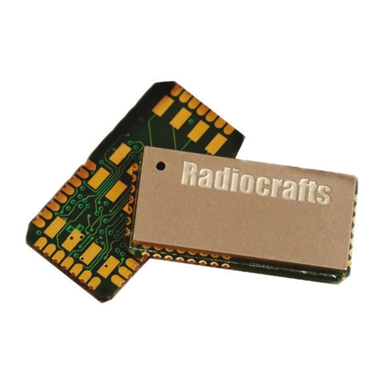
Radiocrafts MPC1 Series User manual

MPC1 User Manual
RC1180-MPC1
RC1701HP-MPC1

Page 1of 29
©2019 Radiocrafts AS
RC1180-MPC1/RC1701HP-MPC1 User Manual (rev. 1.1)
RC1180-MPC1
USER MANUAL RC1701HP-MPC1
Table of Contents
1INTRODUCTION..............................................................................................................................2
1.1 QUICK START............................................................................................................................2
1.2 COMPARING MPC1 AND MBUS3/MBUS4 MODULES ..................................................................2
2WIRELESS M-BUS EMBEDDED PROTOCOL ..............................................................................3
3CONFIGURING THE MODULE OVER THE UART INTERFACE ..................................................4
3.1 SET THE MPC1 MODULE IN CONFIG MODE................................................................................4
3.2 AVAILABLE CONFIGURATION COMMANDS .....................................................................................4
3.3 EXIT CONFIG MODE AND RETURN TO SLEEP............................................................................4
4SET UP AND USE THE PULSE INPUTS .......................................................................................5
5SET UP AND USE THE INSTALLATION PIN ................................................................................6
6SET UP AND USE THE TAMPER PIN ...........................................................................................7
7SET UP AND USE ENCRYPTION ..................................................................................................8
8SET UP AND USE OTA (OVER THE AIR) CONFIGURATION......................................................9
9DOCUMENT REVISION HISTORY...............................................................................................10
APPENDIX A CONFIGURATION COMMANDS...................................................................................11
APPENDIX B CONFIGURATION MEMORY........................................................................................14
APPENDIX C CONFIGURATION MEMORY DEFAULTS....................................................................19
APPENDIX D EXAMPLES....................................................................................................................20
Table of Tables
Table 1 –MPC1 Configuration Commands overview.................................................................................4
Table 2 –SND-IR Message example.........................................................................................................6
Table 3 –Configuration Memory ..............................................................................................................14
Table of Figures
Figure 1 –Wireless M-Bus Packet .............................................................................................................3
Figure 2 –Pulse Pin connection, R1 ~ 0-10k Ohm....................................................................................5
Figure 3 –OTA123 flow..............................................................................................................................9
Table of Examples
Example 1 –Set encryption key via UART.................................................................................................8
Example 2 –Set desired MBUS_MODE and TX_INTERVAL..................................................................20
Example 3 –Set Manufacturer ID, Unique ID, version and device information .......................................21
Example 4 –Set desired TX_INTERVAL .................................................................................................22
Example 5 –Example message –SND-NR sent from dual electricity meter..........................................23
Example 6 –Example message –Configuration message (OTA123, step 1), RC1701HP-MPC1 ........24
Example 7 –Example message –Configuration message (OTA123, step 1), RC1180-MPC1..............25
Example 8 –Example message –Configuration setting message (OTA123, step 2) ............................26
Example 9 –Example message –Reset message (OTA123, step 2) ....................................................27
Example 10 –Example message –Two pulse counters and flow for both.............................................28
Abbreviations
Abbreviation
Description
MPC
Wireless M-Bus with Pulse Counter
OTA
Over The Air
DLMS
Design Language Message Specification
https://www.dlms.com/eng/get-a-flag-id-37062.shtml

Page 2of 29
©2019 Radiocrafts AS
RC1180-MPC1/RC1701HP-MPC1 User Manual (rev. 1.1)
RC1180-MPC1
USER MANUAL RC1701HP-MPC1
1 Introduction
1.1 Quick Start
The MPC module is intended to be used as a Wireless M-Bus slave node, transmitting data from any meter (like
gas-, water-, heat- or electricity meter), transmitting messages that can be received by any standard Wireless M-
Bus receiver, like the Radiocrafts RC11x0-MBUS3 and RC17xx–MBUS4, acting as Master in the system. The
meter(s) needs to be connected to the MPC module’s PULSE1 or PULSE 2 (or both) inputs. The module is
normally in sleep mode with ultra-low power consumption, only counting and accumulating pulse inputs when the
PULSE1/PULSE2 inputs goes low or high. At a configurable interval, the module wakes up and makes an RF
transmission of the accumulated value. The module can also be used without pulses to the pulse counter input and
will then act as a general ID- and status transmitter.
How do I configure the MPC1 module?
The module has a UART interface which is used for initial setup of the module. For available commands and
configuration parameters –please see Appendix A and Appendix B.
As part of the initial setup, you can enable Over The Air (OTA123) configuration. This is described further in
chapter 8.
What about the antenna?
In most cases a simple quarter wavelength wire or a PCB track will do. Connect a piece of wire to the RF pin with
length corresponding to the quarter of a wavelength. For space limited products, contact Radiocrafts and we will
recommend the best antenna solution for your application.
Radiocrafts also offer an application note on tuning a 169 MHz antenna in AN025, found here:
https://radiocrafts.com/resources/application-notes/
Examples
The Appendix D of this user manual contains examples of how to perform various configurations.
1.2 Comparing MPC1 and MBUS3/MBUS4 modules
The RC1180-MPC1 and RC1701HP-MPC1 modules are buildt on the RC1180-MBUS3 and RC1701HP-MBUS4
modules respectively. However –they are enhanced to work as autonomous slave units without the need for an
external MCU.

Page 3of 29
©2019 Radiocrafts AS
RC1180-MPC1/RC1701HP-MPC1 User Manual (rev. 1.1)
RC1180-MPC1
USER MANUAL RC1701HP-MPC1
2 Wireless M-Bus Embedded Protocol
During the RF transmission, the module transmits a data frame according to EN13757-3/4. At the MBUS receiver,
the format of the payload will look like this:
Figure 1 –Wireless M-Bus Packet
L
Added automatically. Does not include itself, nor START/STOP bytes.
C
Configured in module. Added automatically.
HEADER
Configured in module. Added automatically.
CI
Configured in module. Added automatically.
APPL_DATA
Application data including packet counter, tamper info and pulse counting values for
the two inputs (4 bytes for each pulse input). Added automatically.
The MPC1 module will transmit the data points using the M-Bus application protocol (EN 13757-3). The type and
number of data points included in the message depends on the configuration of the module (one or two pulse
inputs). The DIF and the VIF are the descriptors used.
A “short header” (transport layer) is used for status and encryption information. The STATUS byte contains the
battery alarm bit (0x04) and tamper bit (0x20). The tamper monitoring is enabled through the module configuration.
To fully understand the protocol and details like packet format, configuration, sleep modes and so on for a
complete Wireless M-Bus setup, please refer to the Data Sheet and the User Manual for RC1xx0-MBUSx found on
the Radiocrafts website www.radiocrafts.com.

Page 4of 29
©2019 Radiocrafts AS
RC1180-MPC1/RC1701HP-MPC1 User Manual (rev. 1.1)
RC1180-MPC1
USER MANUAL RC1701HP-MPC1
3 Configuring the module over the UART interface
Connect to the UART interface with these settings:
•Baud rate: 19200
•Data bit: 8
•Stop bit: 1
•Parity control: None
•Flow control: None
3.1 Set the MPC1 module in CONFIG mode
The MPC1 module is in sleep mode between each transmission, so to enter CONFIG mode you need to first send
0xFF to wake it up, then send 0x00 to enter config mode.
3.2 Available configuration commands
The table below shows an overview of the available commands.
Table 1 –MPC1 Configuration Commands overview
Command
Parameter
RC1180-MPC1
RC17xxHP-MPC1
Stored in NVM
(Flash)
Stored in RAM
ASCII
hex
‘M’
0x4D
Memory configuration
✔
✔
✔
✘
See Appendix A for
details.
‘X’
0x58
Exit command
✔
✔
–
–
‘Y’
0x59
Memory Read one byte
✔
✔
–
–
‘Z’
0x5A
Sleep mode
✔
✔
–
–
‘0’
0x30
Test mode 0
✔
✔
–
–
‘1’
0x31
Test mode 1
✔
✔
–
–
‘2’
0x32
Test mode 2
✔
✔
–
–
‘3’
0x33
Test mode 3
✔
✔
–
–
‘4’
0x34
Test mode 4
✔
✔
–
–
‘7’
0x37
Test mode 7
✘
✔
–
–
‘8’
0x38
Test mode 8
✘
✔
–
–
‘@RC’
0x40 0x52 0x43
Reset Configuration to factory defaults
✔
✔
✔
✘
‘@RR’
0x40 0x52 0x52
Reset Radio
✔
✔
–
–
3.3 Exit CONFIG mode and return to SLEEP
When you have configured the module, you can send either ‘Z’ or ‘X’ to exit CONFIG mode and go back to SLEEP
(normal operation).

Page 5of 29
©2019 Radiocrafts AS
RC1180-MPC1/RC1701HP-MPC1 User Manual (rev. 1.1)
RC1180-MPC1
USER MANUAL RC1701HP-MPC1
4 Set up and use the pulse inputs
The meter pulse inputs (PULSE1/PULSE2) of the module is between GND and Pin 27/28. These are the same
input as Push Button S5/6 on the Development Board for the module. MPC_IO can enable one or two pulse inputs.
The pulse is counted on negative or positive edge. This is configurable by the configuration parameter
MPC_POLARITY.
The input has configurable pull-up internally to avoid leakage current during pulse (input = 0V). This means the
external circuitry must keep the pin high to ensure no leakage. In case the pulse is generated by an open / short to
ground circuitry, a pullup to VCC is needed. You can choose between adding an external 1MOhm (mega-ohm)
resistor or enabling an internal pullup set by configuration parameter MPC_PULLUP. Adding the external pullup will
give a lower current consumption.
Figure 2 –Pulse Pin connection
C1 together with R1 can be used to filter the pulse input, but do not use too much filtering as this will reduce the
rise/fall time of the pulse.
If the UART is not connected to any circuitry during operation, make sure to include a pull-up resistor to RXD. Data
to this pin will wake up the module from sleep.
R1 ~0-10k ohm

Page 6of 29
©2019 Radiocrafts AS
RC1180-MPC1/RC1701HP-MPC1 User Manual (rev. 1.1)
RC1180-MPC1
USER MANUAL RC1701HP-MPC1
5 Set up and use the Installation pin
INSTALL can be enabled by setting configuration parameter MPC_IO, and the polarity of INSTALL is set by
configuration parameter MPC_POLARITY. You can also enable an internal pullup for INSTALL in the same way as
it can be done for other inputs. This is enabled by configuration parameter MPC_PULLUP.
When INSTALL is enabled as described above, and it is activated - the MPC will start the transmission of
installation request messages (SND-IR) with CI = 0x7A, no application data. The module will send a new SND-IR
message every 30-60s until installation mode is exited (see below) or it reaches it’s maximum number of
retransmissions (totally 90 messages).
If INSTALL is activated again, the module exits installation mode, terminates the SND-IR transmissions and return
to sleep mode (normal operation).
The module does not expect, or listen for, an Installation confirmation (CNF-IR)
The installation request message will be:
0x0E
0x46
0x24
0x48
0x78
0x56
0x34
0x12
0x01
0x02
0x7A
0x00*
0x00
0x00
0x00
Table 2 –SND-IR Message example
Value
Name
Description
0x0E
Length
Length
0x46
C-Field
SND-IR
0x24 0x48
M_ID
Manufacturer ID. Value configured in configuration parameter M_ID1
and M_ID2
0x78 0x56 0x34 0x12
U_ID
Serial number. Value configured in configuration parameters U_ID1,
U_ID2, U_ID3, and U_ID4
0x01
VER
Value configured in configuration parameters VER
0x02
DEV
Device Type = Electricity. Value configured in configuration
parameters DEV
0x7A
CI-field
Indicating short header
0x00 *
Short header
This byte will contain access number, which is increased
automatically for each message sent.
0x00
Status byte. This byte will contain information about Tamper and
Battery alarm.
0x00 0x00
Configuration word. No encryption enabled.

Page 7of 29
©2019 Radiocrafts AS
RC1180-MPC1/RC1701HP-MPC1 User Manual (rev. 1.1)
RC1180-MPC1
USER MANUAL RC1701HP-MPC1
6 Set up and use the Tamper pin
The Tamper pin can be enabled by setting configuration parameter MPC_IO, and the polarity of the tamper
function is set by configuration parameter MPC_POLARITY. You can also enable an internal pullup for the Tamper
pin in the same way as it can be done for other inputs. This is enabled by configuration parameter MPC_PULLUP.
When the Tamper pin is enabled as mentioned above, and the Tamper pin is activated the MPC module will set the
alarm bit in the STATUS byte of the next message. The STATUS byte is found in the transport layer header.

Page 8of 29
©2019 Radiocrafts AS
RC1180-MPC1/RC1701HP-MPC1 User Manual (rev. 1.1)
RC1180-MPC1
USER MANUAL RC1701HP-MPC1
7 Set up and use encryption
The module supports security mode 5, using AES-128-CBC encryption.
The ENCRYPT_FLAG and DECRYPT_FLAG parameters are used to set the flags to enable / disable the
encryption when transmitting and receiving messages.
The 16 byte encryption key is set as part of the configuration memory and can be configured either by UART or
OTA123.
Example 1 –Set encryption key via UART
Example
To set the encryption key to 00112233445566778899AABBCCDDEEFF, send the follow sequence
to the MPC1 using the UART interface:
Command
Hex
Response
Comment/Note
(Wake up)
0xFF
Wake up the UART interface
Enter
0x00
‘>’
Enter CONFIG mode.
Wait for ‘>’ prompt.
‘M’
0x4D
‘>’
M-command entered.
Wait for ‘>’ prompt.
0x40 0x00
(none)
Key’s MSB address and value
0x41 0x11
…
0x4F 0xFF
(none)
Additional address and value pairs
Key’s LSB address and value
(Exit ‘M’)
0xFF
‘>’
Exit M-command
Wait for ‘>’ prompt.
‘Z’
0x5A
(none)
Exit CONFIG mode.
Module returns to SLEEP state
Note! The module does not support encrypted messages for the OTA123 update procedure.

Page 9of 29
©2019 Radiocrafts AS
RC1180-MPC1/RC1701HP-MPC1 User Manual (rev. 1.1)
RC1180-MPC1
USER MANUAL RC1701HP-MPC1
8 Set up and use OTA (Over The Air) Configuration
If the configuration parameter MPC_IO enables the CONFIG pin, an interrupt is used to send the current
configuration data in an SND-NR (C=0x44) message, and listen for a configuration message. The configuration
message from the gateway to the MPC can be either SND-UD (C=0x43) or SND-NR. The length of the listening
window can be configured by the configuration parameter PACKET_TIMEOUT.
Every time you pull the CONFIG pin low, the MPC1 module goes through the below process automatically:
Figure 3 –OTA123 flow
For a normal OTA123 update-cycle you will go through the above flowchart 3 (or 4) times:
Step 1: When CONFIG is activated the current configuration memory is sent from the MPC in an SND-NR
message using CI = 0xAA. Application data is the full dump of the configuration memory. The MPC1 is listening for
an SND-UD message, but will time out and go back to sleep.
Step 2: The MPC will also this time send an SND-NR message with the configuration memory. The gateway must
now be set up to respond to this message with an SND-UD message (SND-NR also accepted). The SND-UD
message can be formatted in two ways, leading to different actions on the MPC:
1. CI = 0xAB. The application data must contain the updated configuration parameters. You can send only the
bytes changed or the full configuration memory. When the MPC receives this message it will update
configuration memory accordingly.
2. CI = 0xAC. The application data is not read by the MPC. Module will reset.
Step 2 must be ran twice if the configuration parameters updated needs a reset to take effect, first with CI=0xAB,
then with CI=0xAC.
Step 3: This step is optional, but since the MPC sends the configuration memory in an SND-NR message when the
CONFIG pin is activated, then this can be used to read back the configuration after the update to confirm that the
result is as expected.
Warning!: If some of the configurations are changed un-intentionally to illegal values, it can set the module
into a not recoverable, nonworking condition. Currently there is no filter on permitted values.
Note! The module does not support encrypted messages for the OTA123 update procedure.

Page 10 of 29
©2019 Radiocrafts AS
RC1180-MPC1/RC1701HP-MPC1 User Manual (rev. 1.1)
RC1180-MPC1
USER MANUAL RC1701HP-MPC1
9 Document Revision History
Document
Revision
Changes
1.00
First official release
1.01
Updated and extended Configuration Memory description according to FW release 0B63.
1.02
Add description of data point formatting and status byte in page 2
1.10
Rewritten to new company standard.

Page 11 of 29
©2019 Radiocrafts AS
RC1180-MPC1/RC1701HP-MPC1 User Manual (rev. 1.1)
RC1180-MPC1
USER MANUAL RC1701HP-MPC1
Appendix A Configuration commands
Command
Details
Comments
ASCII
hex
‘M’
0x4D
Memory Configuration
This command is used to change configuration parameters in
NVM.
When you have sent the M-command you enter memory
configuration mode. Multiple pairs of Address + Data can be
sent before you send the 0xFF command to exit Memory
configuration mode.
Argument
Options
Returns
Address
See Error! Reference
source not found. for
overview of configuration
parameters available.
(none)
Data
Configuration Parameter
value
(none)
Address
(optional)
(none)
Data
(optional)
(none)
Exit
0xFF
Prompt (>)
Caution! The M-
command is writing to
NVM/flash, and this
operation must not be
interrupted by for
example a reset or
powercycle. Interrupting
the NVM update may
leave the configuration
memory corrupted.
Caution! The NVM also
has a limited number of
writecycles (10000x), and
we therefore strongly
recommend that you do
not use the M-command
“in field”, only when
configuring and testing
your module as part of
your production test.
‘X’
0x58
Exit
This command exits configuration mode and sets module back
in idle mode, ready to send/receive data packets.
Argument
Options
Returns
(none)
(none)
(none)
‘Y’
0x59
Memory Read One Byte
Argument
Options
Returns
Address
See Error! Reference
source not found. for
overview of configuration
memory
1 byte value
for given
address
+Prompt (>)
‘Z’
0x5A
Sleep
This command is used to exit configuration mode and at the
same time set module in sleep mode. To exit sleep mode (go to
IDLE again) –send 0xFF on UART RXD.
Argument
Options
Returns
(none)
(none)
(none)

Page 12 of 29
©2019 Radiocrafts AS
RC1180-MPC1/RC1701HP-MPC1 User Manual (rev. 1.1)
RC1180-MPC1
USER MANUAL RC1701HP-MPC1
Command
Details
Comments
ASCII
hex
‘@RC
’
0x40
0x52
0x43
Reset Configuration Memory to factory defaults
This command will reset the configuration memory to the factory
defaults.
Argument
Options
Returns
(none)
(none)
Prompt (>)
At the same time as you run this command you must also assert
the config pin on the module. This is an extra safety to avoid
unintended resets to factory default. It can be disabled by setting
CONFIG_INTERFACE = 1 in the configuration memory.
Note! This command will
also overwrite the serial
number of the module
@’RR
’
0x40
0x52
0x52
Reset
This command will reset the module. It has the same effect as
pulling the reset pin low.
Argument
Options
Returns
(none)
(none)
Prompt (>)
At the same time as you run this command you must also assert
the config pin on the module. This is an extra safety to avoid
unintended resets to factory default. It can be disabled by setting
CONFIG_INTERFACE = 1 in the configuration memory.
‘0’
0x30
Test Mode 0 –List configuration Memory
This command will list all the contents of the non-volatile
configuration memory.
Argument
Options
Returns
(none)
(none)
Configuration
memory
+Prompt (>)
‘1’
0x31
Test mode 1 –TX Carrier
Argument
Options
Returns
(none)
(none)
(none)?
Prompt?
Note! Before using test
mode 1 you need to send
a normal package so that
the TX frequency is
calibrated.
Note!! It is important to
enter Test mode 3 before
exiting the configuration
mode (‘X’) in order to
ensure proper operation
in normal mode.
Note!!! Test mode 4 must
be used between Test
modes 1 and 2.
‘2’
0x32
TX modulated signal, PN9 sequence
Argument
Options
Returns
(none)
(none)
(none)?
Prompt?

Page 13 of 29
©2019 Radiocrafts AS
RC1180-MPC1/RC1701HP-MPC1 User Manual (rev. 1.1)
RC1180-MPC1
USER MANUAL RC1701HP-MPC1
Command
Details
Comments
ASCII
hex
‘3’
0x33
RX mode, TX off
Argument
Options
Returns
(none)
(none)
(none)?
Prompt?
‘4’
0x34
IDLE
Argument
Options
Returns
(none)
(none)
(none)?
Prompt?
‘7’
0x37
Antenna Tuning
This test mode is an antenna tuning function. It will scan
frequency range +/-2 MHz around the centre frequency.
5 seconds between transmissions and 200 kHz separation
between test frequencies.
Argument
Options
Returns
(none)
(none)
(none)?
Prompt?
RC1701HP-MPC1 only.
The test mode ‘7’ and ‘8’
enable frequency sweep
and pulsed transmissions
and can be used to tune
and optimize an antenna.
See AN025:Tuning the
Antenna with Antenna
Tuning Feature for the
detailed procedure.
Use ‘4’before exit.
‘8’
0x38
Pulsed transmission
This command will send 100ms packet for every 5 seconds. It is
used to verify antenna.
Argument
Options
Returns
(none)
(none)
(none)?
Prompt?

Page 14 of 29
©2019 Radiocrafts AS
RC1180-MPC1/RC1701HP-MPC1 User Manual (rev. 1.1)
RC1180-MPC1
USER MANUAL RC1701HP-MPC1
Appendix B Configuration Memory
Table 3 –Configuration Memory
Parameter
Addr
(hex)
RC11xx
RC17xxHP
Argument range
Comment
Default/
Factory Setting
Radio Configuration
RF_CHANNEL
0x00
✘
✔
RC11xx: N.A.
RC17xxHP: 1-41
N mode only, see RC17xxHP datasheet for
details.
RC11xx: N.A.
RC17xxHP: 0x03
RF_POWER
0x01
✔
✔
1-5
Default RF output power [dBm]
RC11xx
RC17xxHP
1
0x01
-20
+14
2
0x02
-10
+17
3
0x03
0
+20
4
0x04
+5
+24
5
0x05
+10
+27
0x05
DATA_RATE
0x02
✘
✔
RC17xxHP: 1-2,5
RF data rate
RC11xx
RC17xxHP
1
0x01
-
2.4kbps
2
0x02
-
4.8kbps
5
0x05
-
6.4kbps
RC11xx: N.A.
RC17xxHP: 0x01
MBUS_MODE
0x03
✔
✔
RC11xx: 1,3,9
RC17xxHP: 17
RC11xx
RC17xxHP
1
0x01
T1
-
3
0x03
S1
-
9
0x09
C1*)
17
0x11
-
N1
*) Datarate accuracy not within limits given in
Wireless M-Bus standard. Packets can be
received by RC11xx-MBUS3 modules.
RC11xx: 0x01
RC17xxHP: 0x11
Device Configuration
PREAMBLE_LENGTH
0x0A
✘
✔
0-2
DLL Frame format A or B
RC11xx
RC17xxHP
0
0x00
-
FFA
2
0x02
-
FFB
RC11xx: 0x00
RC17xxHP: 0x00
PACKET_TIMEOUT
0x10
✔
✔
0x01 –0xFF
OTA configuration listening window after TX
0xCC: 2s
TX_INTERVAL_H/L
0x2D
0x2E
✔
✔
0x0001-0xFFFF
Interval (s) = TX_INTERVAL*0.9s
Default 5 seconds.
0x0006
M_ID1
0x19
✔
✔
0x00-0xFF
Manufacturer ID, first byte
0x0C
M_ID2
0x1A
✔
✔
0x00-0xFF
Manufacturer ID, second byte
0xAE
U_ID1
0x1B
✔
✔
0x00-0xFF
Unique ID, first byte
0x12
U_ID2
0x1C
✔
✔
0x00-0xFF
Unique ID, second byte
0x34
U_ID3
0x1D
✔
✔
0x00-0xFF
Unique ID, third byte
0x56
U_ID4
0x1E
✔
✔
0x00-0xFF
Unique ID, fourth byte
0x78

Page 15 of 29
©2019 Radiocrafts AS
RC1180-MPC1/RC1701HP-MPC1 User Manual (rev. 1.1)
RC1180-MPC1
USER MANUAL RC1701HP-MPC1
Parameter
Addr
(hex)
RC11xx
RC17xxHP
Argument range
Comment
Default/
Factory Setting
VER
0x1F
✔
✔
0x00-0xFF
Version
0x01
DEV
0x20
✔
✔
Device type
0
0x00
Other (dummy increment)
2
0x02
Electricity
3
0x03
Gas
7
0x07
Water
23
0x17
Dual warm/cold meter
27
0x1B
Room Sensor *)
(Manufacturer specific)
*) Temperature, Battery voltage measured in
the module.
CI_FIELD
0x2C
✔
✔
0x7A: Short transport layer header
Do not change
0x7A
CONTROL_FIELD
0x3B
✔
✔
0x44: SND-NR
Do not change
0x44
Data and configuration interface, UART Serial Port
UART_BAUD_RATE
0x30
✔
✔
UART Baud rate.
BE CAREFUL IF CHANGING AS HOST MAY
LOOSE CONTACT WITH MODULE!
Does not take effect until module is reset.
0
0x00
Not used
1
0x01
2400
2
0x02
4800
3
0x03
9600
4
0x04
14400
5
0x05
19200
6
0x06
28800
7
0x07
38400
8
0x08
57600
9
0x09
76800
10
0x0A
115200
11
0x0B
230400
0x05
DATA_INTERFACE
0x36
✔
✔
0
0x00: MBUS packet with ID and address
Do not change
0x00
CONFIG_INTERFACE
0x37
✔
✔
Configuration interface
As a special protection, the @ commands
require the CONFIG pin to be asserted, but this
can be disabled.
0
0x00
Config pin required for
@ commands
1
0x01
Config pin NOT required for
@ commands
0x00

Page 16 of 29
©2019 Radiocrafts AS
RC1180-MPC1/RC1701HP-MPC1 User Manual (rev. 1.1)
RC1180-MPC1
USER MANUAL RC1701HP-MPC1
Parameter
Addr
(hex)
RC11xx
RC17xxHP
Argument range
Comment
Default/
Factory Setting
LED Outputs
LED_CONTROL
0x3A
✔
✔
0
Use to enable LED0/LED1 for RX/TX packet
indication or UART/RF IDLE mode indicator.
0
0x00
Disabled
1
0x01
RX/TX indicator
2
0x02
UART/RF IDLE indicator
3
0x03
LED0 on when transferring
accepted, received message
on UART
0x00
Encryption
ENCRYPT_FLAG
0x3E
✔
✔
0-1
0
0x00
Disabled
1
0x01
Enabled
If enabled, security mode 5 will be used
(AES128-CBC).
0x00
DEFAULT_KEY
0x40-
0x4F
✔
✔
0x00-0xFF
16 bytes key to be used when encryption is
enabled.
MSB is at address 0x40
LSB is at address 0x4F
0xFF
Pulse counter
MPC_IO
0x08
✔
✔
I/O configuration.
Set bit high to enable input
Does not take effect until module is reset.
0x01
PULSE1
0x02
PULSE2
0x04
TAMPER
0x08
INSTALL
0x10
CONFIG
Values can be combined.
0xFF
MPC_POLARITY
0x09
✔
✔
0,4
Polarity of TAMPER
0x00
Active low
0x04
Active high
0x00
MPC_PULLUP
0x0B
✔
✔
I/O pin pullups.
Set bit high to enable pullup.
0x01
PULSE1
0x02
PULSE2
0x04
TAMPER
Values can be combined.
INSTALL and CONFIG has pull-up always
0x00

Page 17 of 29
©2019 Radiocrafts AS
RC1180-MPC1/RC1701HP-MPC1 User Manual (rev. 1.1)
RC1180-MPC1
USER MANUAL RC1701HP-MPC1
Parameter
Addr
(hex)
RC11xx
RC17xxHP
Argument range
Comment
Default/
Factory Setting
MPC_DEBOUNCE_1
0x0C
✔
✔
0x00-0x05
Debounce setting for Pulse counter 1
1: 1 ms de-bounce
Debounce time = MPC_DEBOUNCE_1*1ms
Warning: Do not change without careful testing
0x01
MPC_DEBOUNCE_2
0x0D
✔
✔
0x00-0x05
Debounce setting for Pulse counter 2
See description for MPC_DEBOUNCE_1
0x01
PULSE_DIVIDER_1
0x0E
✔
✔
1-2
Divider for Pulse counter 1
1
0x01
One pulse per count
2
0x02
Two pulses per count
0x01
PULSE_DIVIDER_2
0x0F
✔
✔
1-2
Divider for Pulse counter 2
See description for PULSE_DIVIDER_1
0x01
MPC_FLOW_1
0x17
✔
✔
0-18
Flow for pulse counter 1
0: Disable
1-18: Flow over N hours
If > 0 a data point for flow will be added. The
value set must correspond to the transmission
interval TX_INTERVAL_H/L in hours
0x00
MPC_FLOW_2
0x18
✔
✔
0-18
Flow for pulse counter 2
See description for MPC_FLOW_1
0x00
COUNTER_1_INIT
0x21-
0x24
✔
✔
32bit initial coutner value for pulse counter 1.
Start value after reset.
Addr 0x21: MSB
Addr 0x24: LSB
Note! COUNTER_1_INIT sets the internal
COUNTER_1_VALUE. The reported counter
status is always COUNTER_1_VALUE /
PULSE_DIVIDER_1.
0x00000000
COUNTER_2_INIT
0x25-
0x28
✔
✔
32bit initial coutner value for pulse counter 2.
Start value after reset.
Addr 0x25: MSB
Addr 0x28: LSB
Note! COUNTER_2_INIT sets the internal
COUNTER_2_VALUE. The reported counter
status is always COUNTER_2_VALUE /
PULSE_DIVIDER_2.
0x00000000

Page 18 of 29
©2019 Radiocrafts AS
RC1180-MPC1/RC1701HP-MPC1 User Manual (rev. 1.1)
RC1180-MPC1
USER MANUAL RC1701HP-MPC1
Parameter
Addr
(hex)
RC11xx
RC17xxHP
Argument range
Comment
Default/
Factory Setting
PULSE_WEIGHT_1
0x2A
✔
✔
0x00-0x07
Pulse scaling for pulse counter 1.
Liters/volume per pulse
0x00
Special case
The value is incremented for
each transmission (even
without pulse). This can be
used for range test as an
"alive message".
0x01
0.01 Liter or Wh pr pulse
0x02
0.1 Liter or Wh pr pulse
0x03
1 Liter or Wh pr pulse
0x04
10 Liter or Wh pr pulse
0x05
100 Liter or Wh pr pulse
0x06
1000 Liter or Wh pr pulse
0x07
10000 Liter or Wh pr pulse
PULSE_WEIGHT is not used for
DEV = 0x00 or 0x1B (Device type)
0x03
PULSE_WEIGHT_2
0x2B
✔
✔
0x00-0x07
Pulse scaling for pulse counter 2.
See description for PULSE_WEIGHT_1
0x03
BATTERY_THRESHOLD
0x2F
✔
✔
0x01-0xFF
Battery voltage alarm threshold.
𝐵𝐴𝑇𝑇𝐸𝑅𝑌_𝑇𝐻𝑅𝐸𝐴𝑆𝐻𝑂𝐿𝐷 = 128 ∗
𝑉
𝑡ℎ
3
1.25
Default value sets Vth to 3.0V.
0x66
MPC_WATCHDOG
0x39
✔
✔
0-1
0
0x00
Disabled
1
0x01
Enabled
0x00

Page 19 of 29
©2019 Radiocrafts AS
RC1180-MPC1/RC1701HP-MPC1 User Manual (rev. 1.1)
RC1180-MPC1
USER MANUAL RC1701HP-MPC1
Appendix C Configuration Memory defaults
RC1701HP-MPC1
RC1180-MPC1
ADDR
0x00
0x08
0x10
0x18
0x20
0x28
0x30
0x38
0x40
0x48
0x50
0x58
0x60
0x68
0x70
0x78
0x80
0x88
0x90
0x98
0xA0
0xA8
0xB0
0xB8
0xC0
0xC8
0xD0
0xD8
0xE0
0xE8
0xF0
0xF8
03 05 01 11 02 00 00 00
FF 00 00 00 01 01 80 80
CC 00 00 01 00 00 17 00
00 48 24 12 34 56 78 01
00 00 00 00 00 00 00 00
00 00 03 03 7A 00 06 66
05 08 00 01 05 00 00 00
00 00 00 44 06 02 00 00
FF FF FF FF FF FF FF FF
00 00 00 00 00 00 00 00
00 00 00 00 00 00 00 00
93 93 93 93 73 03 5E 03
0D 07 06 07 10 10 10 10
0E 0E 0E 0E 10 10 10 10
01 00 00 00 09 9A 8C 9A
3A B0 A0 B0 30 2F 2E 2C
00 52 43 31 37 30 31 48
50 2D 4D 50 43 31 2C 31
2E 31 30 2C 31 2E 30 30
20 20 20 20 20 20 20 20
20 00 00 00 00 00 00 00
00 FF FF FF FF FF FF FF
FF FF FF FF FF FF FF FF
ADDR
0x00
0x08
0x10
0x18
0x20
0x28
0x30
0x38
0x40
0x48
0x50
0x58
0x60
0x68
0x70
0x78
0x80
0x88
0x90
0x98
0xA0
0xA8
0xB0
0xB8
0xC0
0xC8
0xD0
0xD8
0xE0
0xE8
0xF0
0xF8
01 05 03 01 02 00 09 00
FF 00 00 00 01 01 01 01
CC 00 00 01 00 00 17 00
00 48 24 12 34 56 78 01
00 00 00 00 00 00 00 00
00 00 03 03 7A 00 06 66
05 08 00 01 05 00 00 00
00 00 00 44 08 02 00 00
FF FF FF FF FF FF FF FF
00 00 00 00 00 00 00 00
00 00 00 00 00 00 00 00
00 52 43 31 31 38 30 2D
4D 50 43 31 2C 32 2E 30
30 2C 31 2E 30 30 20 00
00 00 00 00 00 00 00 00
FF FF FF FF FF FF FF FF
E0 EA FA 07 84 84 E0 EA
FA 47 84 C4 FF FF FF FF
FF FF FF FF FF FF FF FF
This manual suits for next models
2
Table of contents
Other Radiocrafts Control Unit manuals
Popular Control Unit manuals by other brands

Redi Controls
Redi Controls RuptureSeal RS-2 operation & maintenance

Cisco
Cisco GS7000 Installation and operation guide

TLV
TLV RT3A instruction manual

Cameron
Cameron WHEATLEY 820 Series Installation, operation and maintenance manual

Honeywell
Honeywell 4219 Installation and setup guide

M-system
M-system R3-NC3 instruction manual