RadiSys CE915GM User manual

August2010
©2007–2010byRadiSysCorporation..Allrightsreserved.
RadiSysandProcelerantareregisteredtrademarksofRadiSysCorporation.Allother
trademarks,registeredtrademarks,servicemarks,andtradenamesarethepropertyoftheir
respectiveowners.
*007-02531-0001*
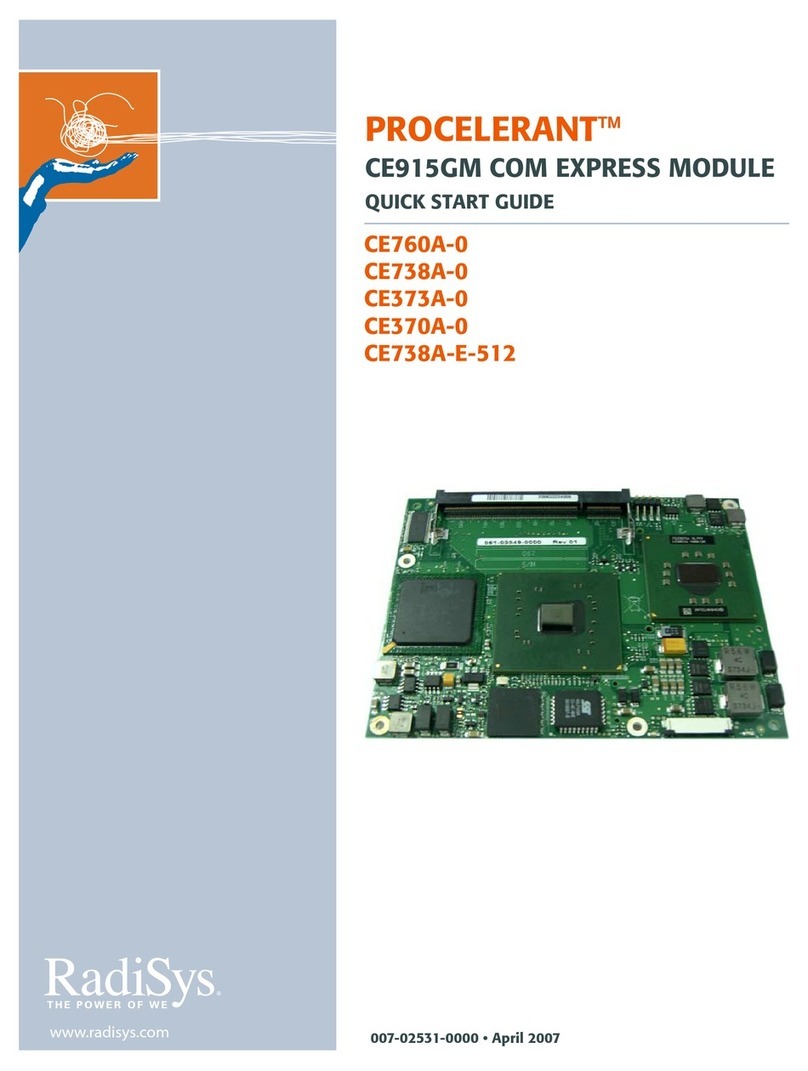
PROCELERANT®
CE915GM COM EXPRESS MODULE
QUICK START GUIDE
FORUSEWITHCE-AHSAACTIVEHEATSINK
Thisguidedescribeshowtoinstall,configure,and
operateaProcelerant®CE915GMCOMExpress
system.TheCR100FlexATXcarrierboardisusedas
thesamplecarrierboard,andtheCE‐AHSAactive
heatsinkisusedasthesampleheatsinkinthisguide.
RefertotheProcelerantCE915GMCOMExpress
ModuleProductManualfordetailedfeatures,
functionality,andspecifications.
Where to get more product information
VisittheRadiSyswebsiteatwww.radisys.comfor
productinformationandotherresources.Downloads
(manuals,releasenotes,software,etc.)areavailable
atwww.radisys.com/downloads.
Handling precautions
WARNING!
• Handle the Procelerant COM Express module and
carrier board with care. Failure to employ
adequate anti-static measures can cause partial
or complete device failure, performance
degradation, or reduced operating life.To avoid
electrostatic discharge (ESD) damage to static-
sensitive components, it is strongly recommended
that you wear a grounded wrist strap or other
static-dissipating device when handling this
product. For further precautions and ESD
information, visit www.radisys.com/esd.
• The battery on the carrier board must be replaced
with the correct type of lithium cell battery (type
CR2032). Using any other battery may damage
the board.

Check your order
2
Check your order
ChecktheRadiSysproductcodesontheCOMExpressmodule,carrierboard,andaccessoriesto
makesureyoureceivedtheproductsyouordered.
COM Express module product codes
Table1liststheCE915GMmodulesavailableatthetimeofpublicationrelease.Allmodulesare
RoHS‐,EN‐,FCC‐,IEC‐,andUL‐compliant.
ChecktheCE915GMproductpageontheRadiSysWebsiteorcontactyoursalesrepresentative
forthelatestinformationaboutproductofferings.Notethatmemorymodulesmustbe
purchasedseparately.
CR100 carrier board product codes
Table2liststheCR100carrierboardsavailableatthetimeofpublicationrelease.
Optional components
System memory
TheCE915GMrequiresonememorymoduletooperate.Forinformationonqualifiedmemory
optionsthathavebeenvalidatedforusewiththeCOMExpressmodule,refertotheProcelerant
CE915GMQualifiedMemoryList.
Table 1. CE915GM product codes
Product name Product code Description
CE915GMA CE760A-0 Intel 2.2GHz Pentium M 760 BGA processor, CE915GM chipset, no memory module, RoHS
CE738A-0 Intel1.4GHz LV Pentium M 738 BGA processor, CE915GM chipset, no memory module,
RoHS
CE373A-0 Intel1.0GHz ULV Celeron M 373 BGA processor, CE915GM chipset, no memory module,
RoHS
CE370A-0 Intel1.5GHz Celeron®M 370 BGA processor, CE915GM chipset, no memory module,
RoHS
CE738A-E-512 Intel1.4GHz LV Pentium M 738 BGA processor, CE915GM chipset, 512MB memory
module, with extended temperature to -25ºC to 70ºC, RoHS
CE915GME CE738B-0 Intel1.4GHz LV Pentium M 738 BGA processor, CE915GM chipset, no memory module,
RoHS
Table 2. CR100 product codes
Product code Description
CR100-2DVI Flex ATX Carrier, Dual DVI
CR100-PCIE16 Flex ATX Carrier, PCIE x16, SVGA

3
Heatsinks
Table3liststheheatsinksofferedbyRadiSysforusewiththeCE915GMsystem.Table4—Table6
showacompletelistofallthecomponentsintheCE‐AHSA,CE‐PHSA,andCE‐PHS17Aheatsink
packages.
Table 3. Heatsink product codes
Product code Description
CE-AHSA Active heatsink assembly (a fan is built into the heatsink) for any COM Express module in a 2U chassis.
The power connector for the CE-AHSA is ATX-compliant.
Heatsink dimensions: 125 x 95 x 26.90mm
Fan dimensions: 80 x 80 x 15mm
Fan power supply: +5V to +13.8V (+12V recommended)
CE-PHSA A passive heatsink for any COM Express module in a 1U chassis. A chassis fan is required with this option.
Dimensions: 125 x 95 x 26.90mm
CE-PHS17A A 17mm low-profile passive heatsink for COM Express modules CE373A or CE738A in a 6HP (ATCA)
blade. An air velocity of 400 lfm [2 m/sec] is required. Use with CE738A requires a chassis fan.
Dimensions: 125 x 95 x 14.94mm
CE-HSPA Heat spreader for CE760A, solid aluminum, compliant with PICMG COM.0 COM Express specification
Revision 1.0
Dimensions: 125 x 95 x 11mm
CE-TIM Thermal compound application bar, phase change at 58ºC (136ºF)
Table 4. CE-AHSA heatsink contents
Product code Description QTY Part number
Backer plate 41x36mm, sheet metal (supplied with four M2 flat head
screws) 1 010-02709-00xx
CE-AHSA Aluminum active heatsink, 125x94x42mm, 12V input 1 019-00352-00xx
Carrier screws M2.5x0.45x4mm, pan head (used to tighten the carrier board
and module) 5 09-0293-00xx
Heatsink screws M2.5x0.45x16mm, panhead(used totightenthe heatsinkand
module) 5 009-01707-00xx
Heatsink spacer M2.5 clear, 4.5mm outside diameter, 6mm long 1 009-01587-00xx
Module screw M2.5x0.45x12mm, pan head (used with the heatsink spacer) 1 09-0344-00xx
Standoffs M2.5x0.45x5mm, hex jam, 4.5mm outside diameter 5 009-01190-00xx
Washers 2.5mm inside diameter, spring lock (used with heatsink
screws) 5 009-01208-00xx

Prepare COM Express components
4
Video adapter
IfyouareusingtheCR100carrierboardandneedtoattachaVGAmonitortoaDVI‐Iport,aDVI‐
to‐SVGAadapterisrequired.RefertoDVIandVGAMonitorsonpage7forfurtherinformationon
VGAsupportonDVI‐Iports.
Prepare COM Express components
LayoutallthecomponentsonagroundedworksurfaceasshowninFigure1topreparefor
assembly.Notethatyoumayhavedifferentpartsdependingonwhatyouordered.
Table 5. CE-PHSA heatsink contents
Product code Description QTY Part number
Backer plate 41x36mm, sheet metal (supplied with four M2 flat head
screws) 1 010-02709-00xx
CE-PHSA Aluminum active heatsink, 125x94x27mm, 12V input 1 019-00352-00xx
Carrier screws M2.5x0.45x4mm, pan head (used to tighten the carrier board
and module) 5 09-0293-00xx
Heatsink screws M2.5x0.45x16mm, panhead(used totightenthe heatsinkand
module) 5 009-01707-00xx
Heatsink spacer M2.5 clear, 4.5mm outside diameter, 6mm long 1 009-01587-00xx
Module screw M2.5x0.45x12mm, pan head (used with the heatsink spacer) 1 09-0344-00xx
Standoffs M2.5x0.45x5mm, hex jam, 4.5mm outside diameter 5 009-01190-00xx
Washers 2.5mm inside diameter, spring lock (used with heatsink
screws) 5 009-01208-00xx
Table 6. CE-PHS17A heatsink contents
Product code Description QTY Part number
Backer plate 41x36mm, sheet metal (supplied with four M2 flat head
screws) 1 010-02709-00xx
CE-AHSA Aluminum active heatsink, 125x95x17mm, 12V input 1 019-00352-00xx
Carrier screws M2.5x0.45x4mm, pan head (used to tighten the carrier board
and module) 5 09-0293-00xx
Heatsink screws M2.5x0.45x16mm, panhead(used totightenthe heatsinkand
module) 5 009-01707-00xx
Heatsink spacer M2.5 clear, 4.5mm outside diameter, 6mm long 1 009-01587-00xx
Module screw M2.5x0.45x12mm, pan head (used with the heatsink spacer) 1 09-0344-00xx
Standoffs M2.5x0.45x5mm, hex jam, 4.5mm outside diameter 5 009-01190-00xx
Washers 2.5mm inside diameter, spring lock (used with heatsink
screws) 5 009-01208-00xx
Product Code Description
CE-DVI-VGA DVI-to-SVGA adapter

5
Figure 1. Basic component preparation
1
2
9
3
8
11
10
47
56
Item Component description Item Component description
1 COM Express module 7 Heatsink spacer and module screw
2 DDR2 memory module 8 Heatsink screws
3 Active heatsink 9 Washers (use with item 8)
4 Backer plate (supplied with four M2 flat head screws) 10 Carrier screws
5 Phase-change thermal interface material, Thermstrate®
TC 11 CR100 FlexATX carrier board
6 Standoffs (use with items 8 and 9)

Prepare COM Express components
6
Power supply
TheCE915GMwillworkwithanATX‐compliantpowersupplyorapowersupplythatiscompliant
withPICMG®COM.0COMExpressSpecificationRevision1.0.Whenselectingapowersupply,be
suretoconsiderthemaximumpower,ACinput,frequency,inputcurrent,andDCout
specificationsofthepowersupply.
Theoretically,theCE915GMrequiresatleast8A onthe+12Vpowerrail.Consideringthepower
consumptionofthecarrierboard,though,itisbesttoallowacertainamountofleewayonthe
twopowerrails.Forthisreason,thepowersupplyshouldberatedabove200 Wattswithatleast
12Aoutputonthe+12Vpowerrail.
AtypicalpowersupplyfortheCR100FlexATXcarrierboardmayhavethesespecifications:
Type:ATX
MaxPower:350W
ACinput:100–120VAC,200–240VAC
Frequency:50/60Hz
Inputcurrent:10A@115V,6A@230V
DCoutput:
Notes:
•ItisrecommendedthatyouuseanATXP4powersupplywitha24‐pincable,whichis
typicallylabeled“BTX.”A20‐pincablecanalsobeused,inwhichcaseyouwouldplugthe20‐
pincableinonthepin#1endofthecarrierboard’sATXpowersupplyconnectorandleave
thetwopairsofpinsontheotherendexposed.Noadapterisrequired.
•Whenmultiplefansareused,additionalamperageisrequired.Forexample,ifa4Uchassis
withtwofanshas2Asurgecurrentforeachfan,16Aisrequired(12A+2A+2A).
CD-ROM/DVD-ROM drives
AUSBCD‐ROM/DVD‐ROMorIDECD‐ROM/DVD‐ROMdriveisusuallyrequiredforyoutoinstall
theoperatingsystemandothersoftware.
Hard disk
StandardcomputerIDEandSATAharddisks(60GB,80GB,120GB,etc.)canbeattachedtothe
carrierboard.TheCR100carrierboardcontainsoneIDEheaderandtwoSATAheaders.
Keyboard and mouse
TheCR100carrierboardsupportsastandardUSBkeyboardandUSBmouse,ratherthanaPS/2
keyboardormouse.
Voltage +3.3V +5V +12V -5V -12V +5V Standby with 12V power supply
Current 14A 30A 15A 0.5A 0.8A 3.0A

7
Video devices
DVI and VGA Monitors
TheCR100‐2DVIcarrierboardcontainstwoDVI‐IportsthatcomplywiththeDigitalVideo
Interface(DVI)specification.Dualindependentdisplayscanbeusedwiththeappropriatedrivers
installed.Alternatively,youcanattachasingleanalogVGAmonitortooneoftheDVI‐Iports.For
detailedinstructions,seeConnectinternaldevicesandsetjumpersonpage19.
Note:ConnectionofaVGAmonitorwithaDB15cableconnectortotheDVIportrequiresaVGA‐
to‐DVIadapter(seeVideoadapteronpage4).
TheCR100‐PCIE16carrierboardisdesignedtouseaPCIExpressgraphicscardinthePCIExpress
x16graphicsslotforhigh‐performancegraphicsacceleration.ThetwoDVI‐Iportsonthiscarrier
boarddonotsupportDVImonitors,butoneoftheportscanbeusedtoattachaVGAmonitor.
Fordetailedinstructions,seeConnectinternaldevicesandsetjumpersonpage19.
LVDS panel
OntheCR100carrierboard,alow‐voltagedifferentialsignaling(LVDS)interfaceallowsthe
connectionofoneLVDSflatpanel.Thisattachmenttypicallyrequiresacustomcable.Usethe
LVDSinterfacepinoutchartintheProcelerantCR100FlexATXCarrierBoardProductManualasa
guideforobtainingasuitablecable.
TV or other S-Video devices
UseastandardMiniDin4maleS‐VideocabletoconnectvideoequipmentorotherS‐Video
compatibledevices.
Ethernet cables
UsetheRJ45EthernetporttoconnecttoaLAN,router,orotherdeviceviaEthernetcable.For
10/100Base‐Tconnections,aCat5cableisrequired.A1000Base‐TconnectionrequiresaCat5E
cable.
Miscellaneous attachments
Additionalinterfaces,suchasanRS‐232port,USBports,frontpanelLEDs,IEEE1394b,and
backlightcontrol,maybeaddedtothechassis.ForconnectorlocationsontheCR100carrier
boardandcableselectionforinternalconnections,refertothecarrierboard‘sdocumentation.

Identify key components
8
Identify key components
Module layout
Figure2—Figure3showthemaincomponentsontheCE915GMmodule.Forinformationon
featuresandfunctionalityofthesecomponents,refertotheProductManual.
Figure 2. Module layout: top view
CPU
DDR2 SO-DIMM
memory socket
Phoenix FirstBIOS
Notebook (Pro) BIOS
Intel 82573V
Ethernet controller
Intel ICH6-M
Mobile Intel 915GM
Express chipset
BIOS operation mode
header
Reset LED (D4)
POST LED (D5)

9
Figure 3. Module layout: bottom view
Carrier board layout
ForlocationsofkeycomponentsontheCR100carrierboard,refertotheProcelerantCR100
FlexATXCarrierBoardProductManual.
Board-to-board
interconnector

Assemble the COM Express system
10
Assemble the COM Express system
Install the memory module
1. InsertonememorymoduleintothelowerDDR2SO‐DIMMmemorysocket.Pressdownon
thecornersofthememorymoduleuntilthelatchesclickintoplace.
2. Toremoveamemorymodule,openthelatchesonbothsidesofthememorysocket,liftthe
freeendofthememorymodule,andremoveitfromthesocket.
Press firmly into place
Memory module
latches

11
Install the active heatsink
1. ApplytheThermstrateTCphase‐changematerialtotheprocessor,GMCH,andICH6‐M
chipsets.Whenassembled,heatfromthechipswillbeconductedthroughthethermal
interfacestotheheatsink.
2. Installtheheatsinkspacerandmodulescrewthroughthemoduleasshownbelow.Thescrew
willsecuretheheatsink.
Heatsink spacer and module screw

Assemble the COM Express system
12
3. Checkthebottomsideoftheheatsinkforcorrectalignmentagainstthemodule.
Against CPU
Against mobile Intel 915GM
Express chipset
Against Intel
ICH6-M
For heatsink spacer
and module screw

13
4. Placetheheatsinkassemblyonthemoduleasshown,liningupthestandoffsontheheatsink
withthescrewholesinthemodule.

Assemble the COM Express system
14
5. Holdthemoduleandheatsinktogetherandturnthemover.Tightenthemodulescrewtoa
torquevalueof0.34N∙m(3lbf∙in).
WARNING! To avoid damaging the module, be careful not to overtighten the screws.
Module screw

15
6. Placetheheatsinkbackerplateonthemoduleasshown.Tightenthesuppliedbackerplate
screwsuntiltheyreachthePCB,andthenbackoff1/2turn.
WARNING! To avoid damaging the module, be careful not to overtighten the screws.
M2 flat head
backer plate screws
Heatsink backer plate

Assemble the COM Express system
16
7. Turntheassemblyoveragain,andinsertthefiveheatsinkscrewsthroughtheirwashersand
intotheholesatthelocationsshown.
8. Theheatsinkscrewswillprotrudethroughthemodule.Usethefive5mmstandoffsshown,
andtightenthescrewstoatorquevalueof0.34N∙m(3lbf∙in).
Heatsink screws
and washers
5mm standoffs

17
9. RadiSysrecommendsyouplacetheassemblyinatemperaturechamberatatemperatureof
60ºCfor10minutestoallowthethermalinterfacematerialtophasechangeandconformto
anoptimalshapebetweenthechipsandheatsink.
Asanalternativetousingatemperaturechamber,youcanperformthisstepimmediately
afterassemblingthesystembytemporarilycoveringtheheatsinktotrapheatandelevate
thetemperature.Toverifythatthetemperaturereaches60ºC,entertheBIOSSetuputilityby
pressingF2duringsystemboot,andnavigatetotheInformation>SystemMonitors
submenu.After10minutesofoperationat60ºC,besuretouncovertheheatsinkbefore
usingthesystemfurther.
WARNING! The CPU may be damaged if this step is not performed prior to operating the
system.
Thiscompletestheassemblyofthemoduleandheatsink.
Install the module and heatsink assembly onto the carrier board
1. Lineuptheboard‐to‐board‐carrierinterconnectorsonthemoduleandtheCR100carrier
board,thenpresstheconnectorsfirmlyintoplace.Whenthemoduleisfullyseated,itsfive
standoffsshouldbetouchingtheCR100carrierboard.
WARNING! To avoid damaging any component, make sure the COM Express module is firmly
seated in the CR100 board’s interconnectors before using screws to complete the assembly.
Board-to-board
interconnector

Assemble the COM Express system
18
2. Plugthefan’s3‐wirecableintotheprocessorfanconnectorontheCR100carrierboard.
3. InsertthefivecarrierscrewsthroughthebackoftheCR100carrierboardatthelocations
shown,thentightenthescrewstoatorquevalueof0.3136N∙m(2.78lbf∙in).
WARNING! Do not overtighten the screws, or the CR100 carrier board may be damaged.
Install the COM Express assembly into the chassis
1. PrepareachassisdesignedtoacceptastandardFlexATX‐sizedboard.
2. RemoveanyI/Oshieldingincludedwiththechassis,andreplaceitwiththeCR100carrier
board’sI/OshieldingfromRadiSys.
3. Fitthemoduleandcarrierboardassemblyintothechassisandsnapthecarrierboard’srear
I/OpanelintotheI/Oshielding.
Note:Toavoidelectromagneticinterference,ensurethatthespringsontheI/Oshieldingare
infullcontactwiththeCR100carrierboard’srearI/Opanel.
4. Usethescrewsandstandoffssuppliedwiththechassistomountthecarrierboard.Torque
valuesvaryaccordingtothesizeandmaterialofthescrewsused.Checkwithyourchassis
manufacturerfortherecommendedtorquevaluesofanyscrewstheyprovide.
Carrier screws

19
Connect internal devices and set jumpers
ThissectiongivestheprocedureforconnectinginternaldevicestotheCR100carrierboard,such
asdiskdrivesandLANcards,andconfiguringjumpersettings.
1. Connectthefollowinginternaldevicestoconnectorsonthecarrierboardasneeded.The
installationorderisnotimportant.Forfurtherinformationaboutattachingdevices,referto
theProcelerantCR100FlexATXCarrierBoardProductManual.
2. IfyouhaveaCR100‐2DVIcarrierboard,youmayneedtospecifywhichDVI‐Iconnectorwill
outputVGAsignalswiththe2‐pinDVIoutputselectionheader.Forinstructionson
connectingaDVIdigitalvideomonitororanalogVGAmonitor,seeConnectexternalI/O
devicesandchassiscomponentsonpage20.
•Pins1and2jumpered(default)—ObtainsanalogVGAoutputfromthesecondaryDVI‐I
portJ2
•Pins1and2open—ObtainsVGAoutputfromtheprimaryDVI‐IportJ1
3. IfyouhaveaCR100‐PCIE16carrierboard,insertaPCIExpressgraphicscardintothePCI
Expressx16graphicsslot.
4. The2‐pinbootBIOSselectionheaderspecifieswhetherthesystemwillusetheBIOSonthe
carrierboardortheBIOSonthemodulewhenbooting:
•Pins1and2open(default)—ThesystemwillbootfromtheCOMExpressmoduleBIOS,
whichisbasedonthePhoenix®FirstBIOS™Notebook(Pro)BIOSwithRadiSysextensions.
•Pins1and2jumpered—ThesystemwillbootfromthecarrierboardBIOS.
Note:RefertoProcelerantCR100FlexATXCarrierBoardProductManualifyouplantoinstall
aBIOSchipontheCR100carrierboard.
5. Connectthepowersupplytothe24‐pinATXPSUconnectorontheCR100carrierboard.The
powersupplyconnectormustbea24‐pinor20‐pin1connectorthatcomplieswithATX
SpecificationVersion2.2.
CR100 connector Device to connect Cable type
Internal USB headers Up to two internal USB devices Standard 5-pin USB cable
PCI Express x1 slot PCI Express x1 device, such as a LAN card N/A
IDE header One IDE device, such as a CD-ROM drive or
hard disk drive Standard IDE cable, complies with the
ATAPI industrial specification
SATA connectors Up to two SATA devices, such as hard disk
drives Standard SATA cable, compliant with SATA
specification 1.0
LVDS flat panel connector One LVDS flat panel Standard 30-pin LVDS cable
Backlight control connector One backlight control connector for the LVDS
flat panel Custom; attaches to 7-pin 1.25mm header
1Ifa 20-pincable isused, plugthe20-pin cablein tothe pin#1 endof theconnector, andleave thetwo pairsof pinsonthe other
end exposed. No adaptor is required. Pin #1 is marked by an asterisk (*) on the CR100 carrier board.

Assemble the COM Express system
20
6. ConnectthepowerswitchandLEDindicatorcablestothefrontpanelI/Oheader.Pin#1is
markedwithanasterisk(*)ontheCR100carrierboard.
Note:TheCR100carrierboarddoesnotsupportthepowerLEDindicator.Ifyouhaveacustom
carrierboardthatsupportsthisfunction,makesurethatyouconnectthecathodeandanodeof
thepowerLEDcablecorrectly.
Connect external I/O devices and chassis components
ConnectexternaldevicestotheconnectorsontherearI/OpaneloftheCR100carrierboard.
1. ConnectthekeyboardandmousetoanyoftheUSBports.
2. IfyouhaveaCR100‐2DVIcarrierboard,connectoneortwomonitorsaccordingtoyour
needs.AssumingyouhaveleftthejumperintheDVIoutputselectionheadertoenableVGA
outputonthesecondaryDVI‐Iconnector:
• ConnectadigitalvideomonitortotheprimaryDVI‐Iconnector.
• ConnectaVGAmonitortothesecondaryDVI‐Iconnector.IftheVGAmonitorcablehasa
DB15connector,youwillneedaDVI‐to‐VGAadaptorasshownbelow(RadiSysproduct
codeCE‐DVI‐VGA).
3. IfyouhaveaCR100‐PCIE16carrierboard,connectoneormoredisplaystothePCIExpress
graphicscardaccordingtotheinstructionsprovidedwiththegraphicscard.
Function Cable setting
Hard disk drive LED
Pins 1 and 3:
• 1: HDD LED cathode (to VCC, typically white in two-
wire cables)
• 3: HDD LED anode (from HD_ACT#)
Reset switch Pins 5 and 7
Power-on switch Pins 6 and 8
Speaker Pins 10 through 16:
• 10: 5V supply
• 12: Audio signal (speaker)
• 14: Not connected
• 16: Audio signal (speaker)
119
220
DVI side of adaptor VGA side of adaptor
Other manuals for CE915GM
1
Table of contents
Other RadiSys Control Unit manuals
Popular Control Unit manuals by other brands

Phoenix
Phoenix BigSound P5 Handbook

Xylem
Xylem FLYGT Pareo DCM 711 Installation, operation and maintenance manual

LEGRAND
LEGRAND 4 131 01 installation instructions

Texas Instruments
Texas Instruments TPS65253 user guide

Logicbus
Logicbus 3540 M user manual

Kessel
Kessel Comfort Instructions for installation, operation and maintenance