RadiSys PROMENTUM ATCA-4500 User manual

-~
ARTISAN
®
~I
TECHNOLOGY
GROUP
Your definitive source
for
quality
pre-owned
equipment.
Artisan Technology
Group
Full-service,
independent
repair
center
with
experienced
engineers
and
technicians
on staff.
We
buy
your
excess,
underutilized,
and
idle
equipment
along
with
credit
for
buybacks
and
trade-ins
.
Custom
engineering
so
your
equipment
works
exactly as
you
specify.
•
Critical
and
expedited
services
•
Leasing
/
Rentals/
Demos
• In
stock/
Ready-to-ship
•
!TAR-certified
secure
asset
solutions
Expert
team
ITrust
guarantee
I
100%
satisfaction
All
tr
ademarks,
br
a
nd
names, a
nd
br
a
nd
s a
pp
earing here
in
are
th
e property of
th
e
ir
r
es
pecti
ve
ow
ner
s.
Find the RadiSys ATCA-4500 at our website: Click HERE

PROMENTUM®
COMPUTE PROCESSING MODULE
INSTALLATION GUIDE
ATCA-4500
This guide describes how to install and set up the
Promentum®ATCA-4500 compute processing module (CPM)
and its optional ATCA-5400 rear transition module (RTM).
Obey ESD precautions
WARNING!Obey the electrostatic discharge (ESD) procedures
described at www.radisys.com/esd when you install the
product. Electrostatic discharge can cause permanent damage
to static-sensitive components in this product.
Important ESD procedures include:
Keep the product in its ESD shielding bag until a step
tells you to remove it.
Put on a grounded wrist strap before you move near or
touch the product.
Install the product only in a grounded work area.
Before you begin
Check all parts and accessories.
Install memory if necessary. For details, refer to the
ATCA-4500 Compute Processing Module Reference.
Included in the package
An ATCA-4500 CPM.
AMC airflow panel.
Optional components
An ATCA-5400 rear transition module (RTM).
DDR3 DIMM memory. See the ATCA-4500 Compute
Processing Module Reference for supported and
preferred DIMM combinations.
Not included in the package
An AdvancedTCA®shelf (such as an ATCA-6000 or
ATCA-6006).
An Advanced Mezzanine Card (AMC).
An operating system (OS) installer.
A USB CD-ROM drive or other USB storage device
from which to retrieve the OS for the initial installation.
The Promentum software distribution CD-ROM image.
Download the image at www.radisys.com/downloads.
A console serial cable (RJ-45 to DE9-S, RadiSys order
code ATCA-SERIAL-CBL). The same cable is included
in shipments of the ATCA-2210 SCM.
Note: This installation guide instructs how to load an OS
from a CD-ROM drive when the CPM is installed. If an OS
is already installed (for example, on a hard disk drive
mounted on an AMC), many of the steps can be ignored.
007-03307-0000 • August 2009
Copyright © 2009 by RadiSys Corporation. All rights reserved.
RadiSys and Promentum are registered trademarks of RadiSys Corporation.
All other trademarks, registered trademarks, service marks, and trade names are the property of their respective owners.
Artisan Technology Group - Quality Instrumentation ... Guaranteed | (888) 88-SOURCE | www.artisantg.com

Installation Guide
2
Hardware installation
Install the AMC—optional
If an AMC will be added to the CPM, follow the steps in the Promentum™ Advanced Mezzanine Card
(AMC) Installation Guide.
Install the rear transition module—optional
The optional RTM can be hot swapped, so
it can be installed before or after the CPM
is installed and while power is applied to
the shelf. This procedure explains where
and how to install the RTM.
Prerequisite: Install any components not
included with the RTM, such as a hard disk
drive and SFP transceivers. For installation
details, see the ATCA-5400 Rear Transition
Module Reference.
1. Identify placement in the back of the
shelf. For example, if the CPM is
installed in slot 1 in the front, the RTM
connects to the back of the shelf in
slot 1.
2. Remove the airflow management
panel, if present, from the back of the
shelf where the RTM will be installed.
3. Remove the RTM from its ESD
shielding bag.
4. Inspect the EMC gasket to make sure it
is free of debris. Lift the RTM ejector
latches to the open position and insert
the RTM into the back panel slot. Use
firm pressure to fully seat the RTM in
the backplane connector. Make sure
the EMC gasket seals the surfaces it
touches.
5. Once the RTM is seated,
simultaneously close both ejector
latches.
6. Tighten the retaining screws in the top and bottom of the RTM panel.
Zone 3
RTM
connector
Ejector
latch
(closed)
Ejector
latch
(closed)
Retaining
screw
Retaining
screw
EMC
gasket
Artisan Technology Group - Quality Instrumentation ... Guaranteed | (888) 88-SOURCE | www.artisantg.com

Hardware installation
3
Install the CPM into an ATCA shelf
The CPM can be hot swapped, which means it can be installed while power is applied to the shelf. This
procedure assumes the power is already applied to the shelf.
1. Determine the node slot where the CPM will be installed. Do not use the slots reserved for the hub
modules (ATCA-2210 SCMs). For example, the hub slots are 7 and 8 on an ATCA-6000 and an
ATCA-6014 shelf, slots 1 and 2 on an ATCA-6006, and slots 8 and 9 on an ATCA-6016 shelf.
2. Remove the CPM from its ESD shielding bag.
3. Lift the ejector latches to the open position. Before inserting the CPM, inspect the EMC gasket to
make sure it is free of debris.
4. Holding the ejector latches in the open position, slide the CPM all the way into the shelf.
5. When the ejector latches reach the latch rail on the shelf, close both ejector latches but open the
bottom or right latch again right away (so only the top or left ejector latch remains closed). This
prevents the CPM from booting. In Set up the BIOS on page 4, you are instructed to close the other
ejector latch and tighten both retaining screws to secure the CPM in the shelf and start the bootup.
6. Make sure the front panel EMC gasket seals the surfaces it touches.
Front panel LED indicators
Connect a computer terminal to the serial port
This section explains how to connect a computer terminal in order to display and interact with the
operating system software.
1. Connect a serial cable to the serial port of the CPM. Cable details are provided in the ATCA-4500
Compute Processing Module Reference.
2. Connect the other end of the cable to the COM port of an external computer terminal, such as a
laptop. See Figure 1 on page 4 for a connection diagram.
3. Configure the terminal emulator on the external computer to match the default settings for the
CPM serial port: 115200 bps, no parity, 8 data bits, 1 stop bit, no flow control. For best display
results, the terminal should be set to 80 columns by 25 lines.
Note: If garbage characters are displayed, check that the same communication parameters are set
for both the serial port and the COM port.
Activity
Power
Out of service
Hot swap
LEDLabel ColorDefinition
LED 1
LED 2
LED 3
H/S
States
Off = Normal operation
Solid blue = Ready for hot swap
Amber = Application defined
Green = Power good
Red or amber = Out of service
Long blink = Searching for Shelf Manager
Short blink = Preparing for removal
Off = Normal operation
OOS
PWR
APP
H/S
Red / Amber
Green
Amber
Blue
Artisan Technology Group - Quality Instrumentation ... Guaranteed | (888) 88-SOURCE | www.artisantg.com

Installation Guide
4
Figure 1. Serial port connection
Connect a CD-ROM drive to the USB port
Connect a CD-ROM drive to the USB port on the front panel of the CPM. Figure 2 illustrates this
connection.
Figure 2. USB port connection
Software configuration and installation
These instructions apply to the first-time installation of an OS in a development or integration lab.
Additionally, this section describes how to choose the BIOS menu items that allow booting from the
device containing the OS installation media. Once the boot device is selected, the OS can be installed
on another hard disk drive device, such as a hard disk drive on an AMC.
Set up the BIOS
1. Insert the operating system CD into the CD-ROM drive.
2. Close the CPM hot swap ejector latch by pushing it toward the center of the front panel to start the
power-on process. The latch should snap into position.
CPM
Serial port
Computer
terminal
COM port
RJ-45 cable
CPM USB port
CD-ROM
USB port
USB cable
OS
CD
Artisan Technology Group - Quality Instrumentation ... Guaranteed | (888) 88-SOURCE | www.artisantg.com

Software configuration and installation
5
3. Tighten the two retaining screws on the front panel to ensure proper connector mating and to
prevent the CPM from loosening due to vibration.
Wait for the blue hot swap LED to turn off and for the power LED to turn solid green. It may take 30
to 40 seconds for the hot swap LED to turn off and 5 to 10 seconds for the CPM to reach the
power-on state. If the hot swap LED does not turn off, make sure the CPM is fully seated and the
latch is completely closed. For more troubleshooting solutions, see the platform reference manual.
4. After the CPM is powered on, the BIOS begins. When the BIOS banner appears, press the F2
function key on the terminal to activate the Main BIOS menu. The following BIOS setup steps are
recommended before initial bootup:
A. Navigate through the Main menu to set the date and time for the system.
B. Make the USB CD-ROM drive the highest priority boot device for OS installation, as follows:
i. Navigate to the Boot menu and select the Boot Option Priorities submenu.
ii. In the Boot Option Priorities submenu, move the USB CDROM option to the top.
For other BIOS setup options, see the ATCA-4500 Compute Processing Module Reference.
C. Save the changes and exit the BIOS.
Install the operating system and RadiSys software packages
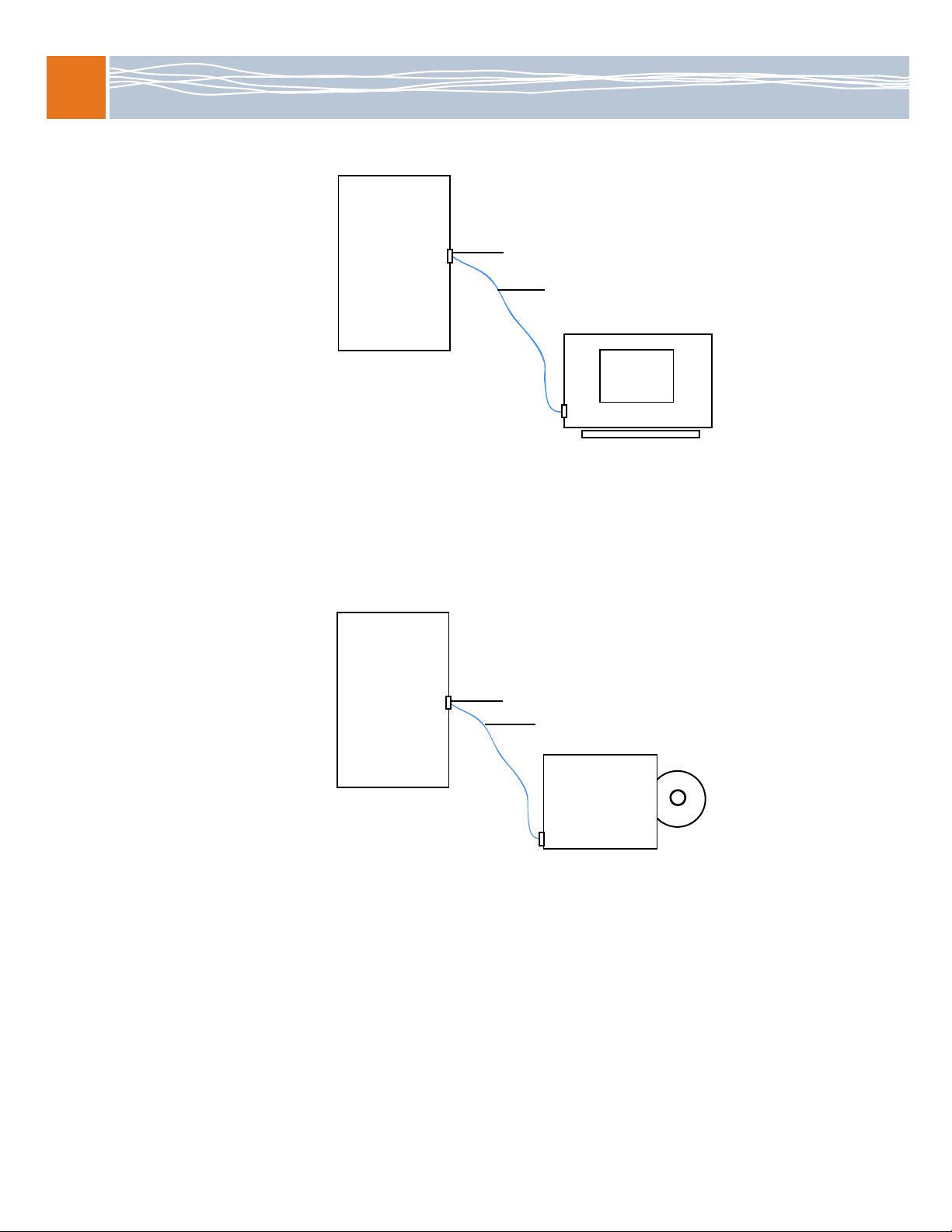
The CPM reboots and loads the operating system from the CD after BIOS changes are saved and you
exit the BIOS. These instructions describe how to install an OS and related RadiSys software.
1. Use the installation directions provided by the OS vendor to install the OS. If you install a version of
Red Hat, be sure to perform the installation in serial mode, which is needed for a device using a
serial connection to a terminal. For example:
boot: linux console=<device>,<speed>
where <device> should be the device you are using (for example, ttyS0 or ttyS1), and <speed>
should be the same as the computer terminal connect speed (115200).
See the RadiSys Developer’s Guide for information about configuring the OS for the CPM and
installing the OS onto a hard disk. The guide is included in the Promentum software distribution.
2. Install the RadiSys RPM packages from the Promentum software distribution (optional). For
information about installing packages, see the Software Guide for Management Processors and
General Purpose Computing Processors. For development information such as cross-compiling
RPMs, see the RadiSys Developer’s Guide.
3. Install the 10 Gb Ethernet driver supplied by the OS vendor. The driver enables the Ethernet
controller and the Fabric interface to function at 10 Gbps. To make the driver start at boot time,
rebuild the module dependencies for the target CPM. For details, see the depmod man page.
Artisan Technology Group - Quality Instrumentation ... Guaranteed | (888) 88-SOURCE | www.artisantg.com

Installation Guide
6
Install the BIOS update driver for rsys-update
BIOS updates for the ATCA-4500 are performed using the rsys-update utility. Before running rsys-
update, the rsysbflash utility and the amifldrv RPM need to be installed. If the required amifldrv RPM is
not available then the driver needs to be built. The driver components and a build script are provided in
an RPM update bundle on the CD.
If a standard RadiSys-provided kernel OS package is used, install the corresponding amifldrv.rpm from
the CD. The installation process names the driver amifldrv_mod.o and places it in the following
directory:
/lib/modules/’uname -r’/extra/amifldrv/
If an appropriate amifldrv.rpm package is not on the CD due to the type of kernel in use on the CPM,
the flash update driver must be built using the rsysbflash utility. Follow these steps to build and install
the flash update driver:
1. Install the appropriate operating system RPM that contains the rsysbflash firmware update utility.
2. Run rsysbflash, passing it the arguments to build the driver.
rsysbflash /MAKEDRV
The utility produces the driver file amifldrv_mod.o. If the driver is built successfully then a
message similar to the following is generated by rsysbflash:
+-----------------------------------------------------------------+
| AMI Firmware Update Utility(APTIO) v2.27 |
| Copyright (C)2009 American Megatrends Inc. All Rights Reserved. |
+-----------------------------------------------------------------+
- Program initializing ..
- Make AFULNX driver .... ok
- Program ended normally.
Note:If a cross-compiled version of Wind River 2.0 is used on the CPM then you must specify the
ARCH and CROSS_COMPILE environment variables before running the
rsysbflash /MAKEDRV
command. The same settings are used that are used to cross-compile the kernel.
See the RadiSys Developer’s Guide for details about environment variables and compiling the kernel.
3. Install the driver to /lib/modules/’uname -r’/extra/amifldrv/. This enables rsys-update to
work with the new driver.
Verify the BIOS driver
Before running rsys-update, verify the BIOS driver is present by entering this command.
rsys-update --versions
The --versions option shows version information for all active, standby, and update bundle
components.
See the Firmware and Software Update Instructions for more information about running rsys-update.
Where to get more product information
Visit the RadiSys Web site at www.radisys.com for product information and other resources. Downloads
(manuals, release notes, software, etc.) are available at www.radisys.com/downloads.
Artisan Technology Group - Quality Instrumentation ... Guaranteed | (888) 88-SOURCE | www.artisantg.com

Artisan
Technology
Group
is
an independent supplier
of
quality pre-owned equipment
Gold-standard
solutions
Extend the life
of
your
critical industrial,
commercial, and military systems
with
our
superior service and support.
We
buy
equipment
Planning to
upgrade
your current
equipment? Have surplus equipment taking
up shelf space? We'll give it a
new
home.
Learn
more!
Visit us at artisantg.com for more info
on price quotes, drivers, technical
specifications, manuals, and documentation.
Artisan Scientific
Corporation
dba
Artisan
Technology
Group
is
not
an affiliate,
representative,
or
authorized
distributor
for
any
manufacturer
listed herein.
We're here to make your life easier.
How
can
we
help you today?
(217)
352-9330
Isales@artisantg.com I artisantg.com
This manual suits for next models
1
Table of contents
Other RadiSys Control Unit manuals
Popular Control Unit manuals by other brands

National Instruments
National Instruments PXIe-7902 Getting started guide

UTC Fire and Security
UTC Fire and Security Edwards Signaling E-IDCWS Installation sheet

Wilo
Wilo Stratos Smart IF module Installation and operating instructions

Siemens
Siemens SINUMERIK user manual

Danfoss
Danfoss MSV-F2 DN Series operating guide

Keysight Technologies
Keysight Technologies 85091D reference guide