RadiSys PROMENTUM ATCA-9100 User manual

-~
ARTISAN
®
~I
TECHNOLOGY
GROUP
Your definitive source
for
quality
pre-owned
equipment.
Artisan Technology
Group
Full-service,
independent
repair
center
with
experienced
engineers
and
technicians
on staff.
We
buy
your
excess,
underutilized,
and
idle
equipment
along
with
credit
for
buybacks
and
trade-ins
.
Custom
engineering
so
your
equipment
works
exactly as
you
specify.
•
Critical
and
expedited
services
•
Leasing
/
Rentals/
Demos
• In
stock/
Ready-to-ship
•
!TAR-certified
secure
asset
solutions
Expert
team
ITrust
guarantee
I
100%
satisfaction
All
tr
ademarks,
br
a
nd
names, a
nd
br
a
nd
s a
pp
earing here
in
are
th
e property of
th
e
ir
r
es
pecti
ve
ow
ner
s.
Find the RadiSys ATCA-9100 at our website: Click HERE

PROMENTUM®
MEDIA RESOURCE MODULE
INSTALLATION GUIDE
ATCA-9100
Thisdocumentdescribeshowtoinstallandtoset
upthePromentum®ATCA‐9100MediaResource
Module(MRM).
Before you begin
Toensureallsafetyprecautionsarefollowedduring
installationandsetup,reviewthePromentumSafety
InformationdocumentontheATCA‐9100MRM
downloadspageatwww.radisys.com/downloads.
Obey ESD procedures
WARNING!Obeytheelectrostaticdischarge(ESD)
proceduresdescribedatwww.radisys.com/esdwhenyou
installtheproduct.Electrostaticdischargecancause
permanentdamagetostatic‐sensitivecomponentsinthis
product.
ImportantESDproceduresinclude:
• KeeptheproductinitsESDshieldingbaguntilastep
tellsyoutoremoveit.
•Putonagroundedwriststrapbeforeyoumovenear
ortouchtheproduct.
•Installtheproductonlyinagroundedworkarea.
Thirdedition,March2011
©2006–2008,2011byRadiSysCorporation.Allrightsreserved.
RadiSysandPromentumareregisteredtrademarksofRadiSysCorporation.AdvancedTCAand
ATCAareregisteredtrademarksofPCIIndustrialComputerManufacturersGroup.Allother
trademarks,registeredtrademarks,servicemarks,andtradenamesarethepropertyoftheir
respectiveowners.
*007-02584-0002*
Artisan Technology Group - Quality Instrumentation ... Guaranteed | (888) 88-SOURCE | www.artisantg.com

ATCA-9100 MRM Installation Guide
2
Prepare for installation
InstallationoftheMRMrequires:
•AnAdvancedTCA®(ATCA®)shelf,suchasaRadiSysATCA‐6000orATCA‐6006shelf
• Adequateventilationfortheshelf
• AdditionalhardwaretoconnecttotheMRMfromanexternalcomputerusingoneofthese
options:
• Connectthroughahubmoduleintheshelf.ThisrequiresastandardcrossoverEthernet
cable.
• Connectthroughareartransitionmodule(RTM).ThisrequiresaRadiSysreardebugcard
(ordercodeTH‐1620‐00)oranRTMdesignedfortheMRM.Inaddition,youneeda
crossoverEthernetcableoranullmodemserialcable.
Install the MRM
ThissectionassumesyouareinstallingthemoduleinanATCAshelfandtheshelfpowerison.
TheATCAshelfarchitectureletsyouinsertandremovethemodulefromtheshelfwithout
poweringdownthesystem.
1. ObeyESDprecautionsandmakesureyouare
adequatelygroundedbeforehandlingthemodule
(seepage 1).
2. Removethemodulefromitsantistaticbag.
3. Openbothejectorhandlesoutwardatthesame
timeasshowninthefigure.
4. Slidethemoduleintooneofthenodeslotsonthe
shelf.Ifcorrectlyaligned,theedgesofthemodule
willfitwithinthenarrowguiderailsoftheshelf.
5. Oncethemoduleisinsertedallthewayintothe
shelf,simultaneouslyclosebothejectorhandles
inward.Thiswillseatthemodule’sconnectorsinto
theshelf’sbackplane.
Thehot‐swap(H/S)LEDflashesuntilthemoduleis
fullypowered(seeFrontpanelLEDindicatorson
page 3).Oncepowered,theH/SLEDwillturnoff
andthePWRLEDwillbecomegreen.
IftheH/SLEDremainssolidblueorkeepsflashing
afterthemoduleisinserted,itindicatesthe
installationmayhavefailed.SeetheATCA‐9100
MediaResourceModuleReferenceforinformation
ontroubleshootingLEDstates.
6. Securethemoduleinitsslotbyhand‐tightening
thethumbscrewsnexttotheejectorhandles.
Opening the ejector handles
1. Slide latch toward handle.
2. Pull handle out.
1
1
2
2
Artisan Technology Group - Quality Instrumentation ... Guaranteed | (888) 88-SOURCE | www.artisantg.com

Front panel LED indicators
3
Front panel LED indicators
Install an RTM (optional)
AnRTMcanbeusedtoprovideI/OaccesstotheMRM.TheRTMmustbedesignedfor
compatibilitywiththeMRM.RadiSysdoesnotcurrentlymanufactureanRTMforusewiththe
MRM.
AnRTMcanbeinstalledatanytime.IfyouwillusetheRadiSysreardebugcardinsteadofan
RTM,seeInstallthereardebugcard(optional).
Preparation
BeforeinstallinganRTM:
1. ObeyESDprecautions.Seepage 1formoreinformation.
2. IdentifythefrontnodeslotwhereyouinstalledtheMRM.TheRTMwillbeinstalledinthe
rearslotdirectlybehindit.Forexample,ifyouinstalledtheMRMinfrontslot 3,theRTMgoes
inrearslot 3.
3. Removetheairflowmanagementpanelinstalledintherearslot.
4. RefertotheRTM’sdocumentationforinstallationinstructions.
Application
Power
Out of service
Hot swap
LEDLabel ColorDefinition
LED 1
LED 2
LED 3
H/SH/S
APP
PWR
OOS
States
Solid blue = Ready for hot swap
Green or amber = Application-defined
Green = Power supplies were good initially,
and power has not been removed
Amber = Application-defined
Off = The MRM is not powered on
Red or amber = Application-defined
Long blink = Searching for Shelf Manager
Short blink = Preparing for removal
Off = Normal operation
DSP stateLED3DSP# Green = Application-defined
Red = Application-defined or DSPs are
initialized with no application loaded
Artisan Technology Group - Quality Instrumentation ... Guaranteed | (888) 88-SOURCE | www.artisantg.com

ATCA-9100 MRM Installation Guide
4
Install the rear debug card (optional)
Inalabenvironment,theRadiSysreardebugcardcanbeusedforI/Oaccessasanalternativeto
anRTM.TheMRMmustbeinstalledintheshelfbeforeyouinstallthereardebugcard.
ToinstalltheRadiSysreardebugcard:
1. Usetheinstructionslistedin
Preparationonpage 3.
2. MakesuretheMRMisalready
installed.
3. Removethereardebugcardfromits
antistaticbag.
4. IfyouplantousetheBaseEthernetor
FabricEthernetport,installanSFP
transceivermoduleintothe
correspondingsocket.
Bothsocketssupportcopperoroptical
gigabitEthernetSFPtransceivers.The
transceiversoperateat1Gbpswithno
auto‐negotiation.
5. Slidethedebugcardintotheempty
rearslotintheshelfalongthetop
guiderail.
Thedebugcardalignmentpinsand
connectorslideintotheMRM
alignmentholesandconnector.
Thereardebugcardpowersupimmediately.
Important:Thereardebugcardisnotdesignedtosupportthefullweightofcables.Whenyou
connectcables,useappropriatecablerestraintstoreducethestressonthedebugcard
connectorsthatmatewiththeMRM.
Serial
console
port
Ethernet
maintenance
port
Base
Ethernet
socket
Fabric
Ethernet
socket
Rear debug card
Artisan Technology Group - Quality Instrumentation ... Guaranteed | (888) 88-SOURCE | www.artisantg.com

Connect to an external computer and the network
5
Connect to an external computer and the network
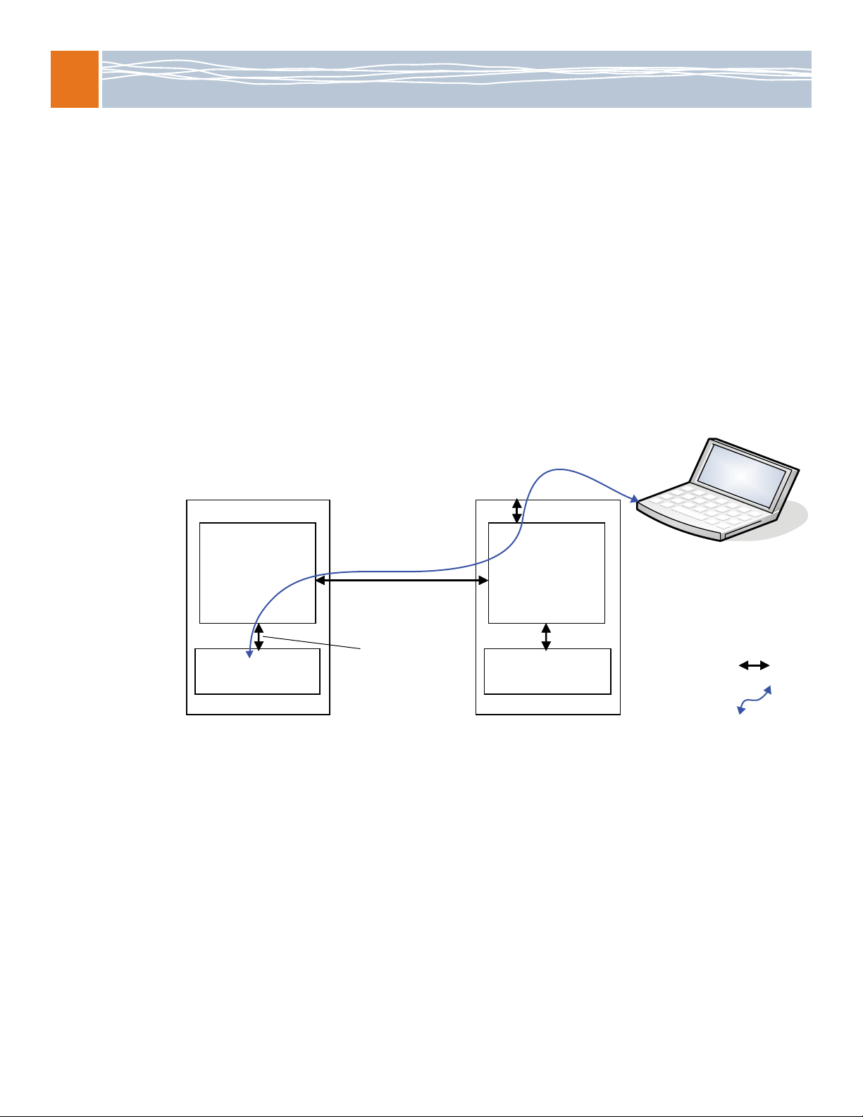
Connecttoanexternalcomputerandthenetworkusingoneofthesemethods:
•Method1:WithanoptionalRTMdesignedtomatewiththeMRMorwiththereardebugcard
•Method2:ThroughanothermoduleviathebackplaneEthernetinterfaces
Method 1: Connect with the RTM or rear debug card
TheMRMcanbeaccessedbyanexternalcomputerthroughtheserialportandtheEthernet
maintenanceportonanRTMorreardebugcard.Usetheserialporttoperformdiagnosticand
verificationprocedures.UsetheEthernetmaintenanceporttoconnecttheMRMtothenetwork
andtoperformconfigurationprocedures.
Connect to the serial port
1. ConnectanullmodemserialportcablebypluggingoneendintotheserialportontheRTMor
reardebugcard.
2. Connectthecable’sotherendtotheCOM1ortheCOM2serialportofanexternalcomputer,
suchasalaptop.
3. Startaterminal‐emulatorapplication,suchasProcommPlus®orminicom,fromtheoperating
systemonyourcomputerorlaptop.Specify115200baud,8databits,noparity,onestopbit,
andnohardwareorsoftwareflowcontrol.
4. PresstheEnterkeytogettheATCA‐9100loginprompt.
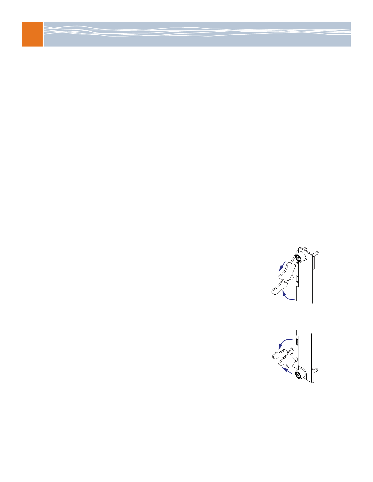
Iftheloginpromptdoesnotdisplay,checkthecablingandverifytheterminal‐emulator
settingsarecorrect.YoucanalsochecktheLEDstatesonthemodule.Ifnecessary,pressthe
RTMresetbuttonandseeifanytextisdisplayed.Displayedtextmayprovidehintsabout
otheritemstocheck.
5. Enteradminattheprompt.
6. VerifythatyoureceiveawelcomemessageandapromptshowingATCA‐9100#.Fromthis
promptyoucanperformdiagnosticandverificationprocedures.Tologoffthemoduleatany
time,enterthe exitcommand.
Connect to the Ethernet maintenance port
1. ConnectacrossoverEthernetcablebetweentheRJ‐45Ethernetmaintenanceportonthe
RTMandtheRJ‐45EthernetportonaLinuxhostcomputerthatisconnectedtoyournetwork.
2. ConfigurethehostcomputertoasubnetIPaddressof10.0.0.<x>.Forthe<x>variable,select
avaluefromtherange2‐254(forexample,10.0.0.2to10.0.0.254).Setthenetmaskto
255.255.255.0.
3. Fromthehostcomputer,useaTelnetconnectiontoaccessthemodule’sdefaultIPaddress
10.0.0.1(port 23).TheATCA‐9100loginpromptforthemodulewilldisplay.
IftheATCA‐9100loginpromptdoesnotdisplay,verifythemodule’sIPaddressiscorrectinthe
Telnetcommand.
Artisan Technology Group - Quality Instrumentation ... Guaranteed | (888) 88-SOURCE | www.artisantg.com

ATCA-9100 MRM Installation Guide
6
4. LoginasadmintogettheATCA‐9100#prompt.Fromthispromptyoucanperform
configurationprocedures.Tologoffthemoduleatanytime,enterthe exit command.
Note:ToconnecttotheLinuxshellonthemodule,useeitheraserialportoraTelnet
connection.Afterconnecting,loginasrootandenterifconfigtovieweth0configuration
settings.
Method 2: Connect through another module via the backplane Ethernet interfaces
IfconnectingwithanRTMorreardebugcardisnotpossible,youcanaccesstheMRMby
connectinganexternalcomputertoanothermoduleintheshelf.
ToconnecttotheMRMthroughanothermodule:
1. Findthehubmoduleinthelower‐numberedhubslot.Onthehubmodule,findanunused
EthernetportthatconnectstotheBaseinterface.Thediagrambelowillustratesthe
connectiontotheMRMwhenanATCA‐2210SCMislocatedinthelower‐numberedhubslot.
IfthehubmoduledoesnothaveaBaseEthernetportavailablebutisalreadyconfiguredfor
networkaccess,youcanuseTelnetoverthenetworktoconnecttothehubmodule(inthe
lower‐numberedhubslot).FromthereyoucanuseTelnettoconnecttotheMRMas
describedinstep4.Inthisscenario,youcanskipsteps2and3.
Note:TheMRMdefaultsettingsallowBaseinterfaceaccesstoonlythelower‐numberedhub
slot.Ifahubmoduleisnotavailableinthelower‐numberedhubslot,movetheinstalledhub
moduletothatslotorpurchaseareardebugcard.
2. ConnectanEthernetcablebetweentheEthernetportonthehubmoduleandtheEthernet
portontheexternalcomputer.
Base Ethernet
Switch
Front Panel
Base Port (e.g., 1/6)
Local Management
Processor
Base Backplane
Link
Media Resource Module
(MRM)
ATCA-2210 SCM
(Hub Module)
eth1 Interface
Base Ethernet
Switch
Local Management
Processor
Interface
Telnet
connection
=
=
Artisan Technology Group - Quality Instrumentation ... Guaranteed | (888) 88-SOURCE | www.artisantg.com

Verify Ethernet switch
operation
7
3. ConfiguretheIPaddressoftheexternalcomputerusingthefollowing:10.2.<chassis>.<x>.
The<chassis>parameterrepresentstheshelfaddress(thephysicallocationoftheshelfwithin
acentraloffice).Forthe<x>variable,selectavaluefromtherange17‐254(forexample,
10.2.<chassis>.17to10.2.<chassis>.254).Setthesubnetmaskfortheinterfaceto
255.255.0.0.
4. FromtheexternalcomputeruseaTelnetconnectiontoaccesstheeth1:0interfaceonthe
MRM.ThestaticIPaddressis:10.2.<chassis>.<slot>.
The<chassis>parameterrepresentstheshelfaddress,andthe<slot>parameterrepresents
theMRM’slocationintheshelf.
TheATCA‐9100loginpromptwilldisplay.Ifthepromptdoesnotdisplay,verifytheTelnet
connectiontotheIPaddressiscorrect.
5. LoginasadmintogettheATCA‐9100#prompt.Fromthispromptyoucanperform
configurationprocedures.TologofftheMRMatanytime,enterthe exit command.
6. DisconnecttheEthernetcablefromtheBaseEthernetportonthehubmoduleyouconnected
throughwhenyouaredoneperformingtheconfigurationprocedures.
Verify Ethernet switch operation
UsethesestepstoviewportstatusandtoenableportsontheBaseEthernetandFabricEthernet
switches.
View port status
1. Verifyyouareatthisprompt.
ATCA‐9100#
Ifyouarenotattheappropriateprompt,seeConnecttoanexternalcomputerandthe
networkonpage 5forinstructionsonhowtogetthere.
2. Entertheapplicablecommandfortheswitchyouareverifying.
3. Enterthiscommandtoshowthestatusoftheports.
showportall
Viewtheportstatusinformationtoseewhichportsareenabled(EKeyModeandAdmin
Mode)andconnectedtoapeer(LinkStatus).Ifneeded,pressthespacebartoviewmoreof
thelist.
4. Proceedtotheapplicablesectionorstep:
•Toenableordisablespecificports,seeEnableordisablespecificportsonpage 8.
•Tokeepthedefaultsettings,continuewithstep5.
Switch Command to enter Resulting prompt
Base Ethernet base‐ethernet ATCA‐9100‐Base#
Fabric Ethernet fabric‐ethernet ATCA‐9100‐Fabric#
Artisan Technology Group - Quality Instrumentation ... Guaranteed | (888) 88-SOURCE | www.artisantg.com

ATCA-9100 MRM Installation Guide
8
5. EntertheexitcommandtoreturntotheATCA‐9100#prompt.
Ifyouareaskedtosavechanges,enteryforyesornforno.Ifyouchooseyforyes,this
configurationwillbesavedasthestartupconfiguration.
6. Entertheexitcommandtologoffthemodule.
Enable or disable specific ports
Note:RadiSysrecommendshavingonlyonebackplaneportenabledontheMRMBaseinterface
iftheshelfhastwohubmoduleswithinterconnectedBaseswitchingdomains.Bydefault,
RadiSyshubmodulesconnecttheirBaseswitchingdomains.IftheFabricswitchingdomainsare
alsointerconnected(whichtheyarenotbydefaultonRadiSyshubmodules),onlyonebackplane
portontheMRMFabricinterfaceshouldbeenabled.
1. Verifyyouareattheapplicableswitchprompt.
Ifyouarenotattheappropriateprompt,seeViewportstatusonpage 7forinstructionson
howtogetthere.
2. Usethesestepstoenableordisablespecificports:
a. Enterthiscommand.
configure
b. Enterthespecificport(interface)numbertoenable.
interface<s>/<p>
Where<s> and<p>havethefollowingvalues.
c. Enterthiscommandtoenableaport:
noshutdown
Ifyouaredisablingtheinterface,enter shutdown.
Switch Prompt
Base Ethernet ATCA‐9100‐Base#
Fabric Ethernet ATCA‐9100‐Fabric#
Backplane slots s=0 p=1-2
DSPs 1-10 s=2 p=1-10
DSPs 11-20 s=1 p=1-10
Local management processor (LMP) s=3 p=1
RTM s=4 p=1
Artisan Technology Group - Quality Instrumentation ... Guaranteed | (888) 88-SOURCE | www.artisantg.com

Power up and load software to the DSP devices
9
d. Toenableanotherport,entertheexitcommandandperformtheproceduresdescribed
instepsbandc.
Whenfinishedenablingports,enterthisseriesofcommandstoreturntothe
ATCA‐9100# prompt.
exit
exit
exit
Ifyouareaskedtosavechanges,enteryforyesornforno.Ifyouchooseyforyes,this
configurationwillbesavedasthestartupconfiguration.
3. Entertheexitcommandagain,tologoffthemodule.
Power up and load software to the DSP devices
BydefaulttheDSPfarmsarepoweredoffandnosoftwareisloadedontheDSPdevices.The
procedureinitializestheserialRapidIO(sRIO)switchinordertoaccesstheDSPdevices.The
procedureloadsthesupplieddiagnosticssoftwaretoverifytheDSPdevicescanloadaknown
softwareimage.
TopoweruptheDSPfarmsanddevicesandloadsoftwaretothem:
1. Verifyyouareatthisprompt.
ATCA‐9100#
Ifyouarenotatthisprompt,seeConnecttoanexternalcomputerandthenetworkonpage 5
forinstructionsonhowtogetthere.
2. AccesstheLinuxshell:
linux‐shell
3. Identifythekernelversioninthedirectorypath:
ls‐d/lib/modules/*mrm1
Theoutputshouldlooksimilartothisandwillbeusedfor<base_path>inthenextstep:
/lib/modules/2.6.14.7‐105mrm1
4. LoadthelibraryforthesRIOswitch,usingthebasepathfromthepreviousstep:
insmod<base_path>/kernel/drivers/rapidio/riodev.ko
Forexample:
insmod/lib/modules/2.6.14.7‐105mrm1/kernel/drivers/rapidio/riodev.ko
5. InitializethesRIOswitch:
sriotoolinit
6. PoweruptheDSPfarms:
sriotoolfpon0
sriotoolfpon1
TheDSPLEDsbecomered.
Artisan Technology Group - Quality Instrumentation ... Guaranteed | (888) 88-SOURCE | www.artisantg.com

ATCA-9100 MRM Installation Guide
10
7. ConfigurethesRIOinterfacesontheDSPdevices:
sriotoolidin20
Thevalue20representsallDSPdevices.
8. ConfiguretheDDRmemoryfortheDSPdevices:
sriotoolidcm20
9. LoadtheimageforrunningdiagnosticteststotheDSPdevices:
ForF‐DSPfarms:
sriotoolidpl20/usr/share/fdspdiags.srec
ForT‐DSPfarms:
sriotoolidpl20/usr/share/tidspdiags.srec
Whenthediagnosticsimageisloaded,theDSPLEDsbecomegreenandthismessage
displays:
DSPProgramLoad/ExecuteSuccess
10. ExittheLinuxshellandlogofftheMRM:
exit
exit
Where to go from here
SeetheATCA‐9100MediaResourceModuleReferencefordetailedinformationonthemodule’s
electricalandmechanicalcharacteristicsaswellasthesoftwarespecificallyforcontrollingthe
DSPs.ToconfigureotheraspectsoftheMRM,seetheSoftwareGuideforManagement
ProcessorsandGeneralPurposeComputingProcessors(alsocalledtheSoftwareGuide)andthe
CLIReference.
Youshouldalsosetpasswordsfortherootandtheadminusersandcreateuseraccountsfor
thosewhodonotrequireadministrativeprivileges.SeetheSoftwareGuideformore
information.
Where to get more product information
PleasevisittheRadiSysWebsiteatwww.radisys.comforproductinformationand
otherresources.Downloads(manuals,releasenotes,software,etc.)areavailableat
www.radisys.com/downloads.
Artisan Technology Group - Quality Instrumentation ... Guaranteed | (888) 88-SOURCE | www.artisantg.com

Artisan
Technology
Group
is
an independent supplier
of
quality pre-owned equipment
Gold-standard
solutions
Extend the life
of
your
critical industrial,
commercial, and military systems
with
our
superior service and support.
We
buy
equipment
Planning to
upgrade
your current
equipment? Have surplus equipment taking
up shelf space? We'll give it a
new
home.
Learn
more!
Visit us at artisantg.com for more info
on price quotes, drivers, technical
specifications, manuals, and documentation.
Artisan Scientific
Corporation
dba
Artisan
Technology
Group
is
not
an affiliate,
representative,
or
authorized
distributor
for
any
manufacturer
listed herein.
We're here to make your life easier.
How
can
we
help you today?
(217)
352-9330
Isales@artisantg.com Iartisantg.com
Table of contents
Other RadiSys Control Unit manuals
Popular Control Unit manuals by other brands

Danfoss
Danfoss PVG 100 Service and parts manual

Agilent Technologies
Agilent Technologies 83400 Series user guide

Highcross
Highcross ECM-RS2D Quick reference guide

Pentair
Pentair Autotrol 255 Series Service manual

MSA
MSA SM5000 instruction manual

Optical Systems Design
Optical Systems Design OSD361 Operator's manual