Rainfresh CAFO 948 User manual

1
CAFO948 Air Induction Oxidation Iron Filter
Installation & Operation Manual
(Please save for future reference)
Thank you for purchasing one of our ENVIROGARD / Rainfresh products. We are committed to
ensuring that you are totally satisfied.
If you have any problems, don’t go back to the store– please contact us !
Most issues can be resolved over the phone.
Help Line : 1-800-667-8072 (Monday to Friday 8:30 AM to 5:00 PM EST)
www.rainfresh.ca
TABLE OF CONTENTS
System Specifications .................................................. 2
How the CAFO System Works...................................... 2
Safety Precautions ...................................................... 2
Cautions before Installation......................................... 2
Installation ................................................................... 3
a) Electrical Requirements..................................... 3
b) Unpacking the unit ............................................ 3
c) Installation Location .......................................... 4
d) Plumbing the filter unit...................................... 5
e) Start-up and Programming ................................ 7
i. Level 1 Programming............................... 7
ii. Level 2 Programming............................... 10
iii. Manual Regeneration.............................. 11
Other Features............................................................. 11
Maintenance................................................................ 11
Troubleshooting........................................................... 12
Exploded Diagram & Parts List..................................... 13
Warranty...................................................................... 16

2
SYSTEM SPECIFICATIONS
Model No.
Rated Service
Flow
US GPM (LPM)
Max Flow Rate
US GPM (LPM)
Min. Well
PUMP Flow
Rate
US GPM (LPM)
Inlet /
Outlet
Drain
Electrical
Pressure
Drop
Operating
Pressure
Shipping
Weight
(lbs)
CAFO 948
3 (11.3)
6 (22.7)
5 (19)
3/4"
MNPT
1/2"
Hose
110V
AC
< 15
psig
30 –100
psig
82
Water Temp –4- 38°C (39 - 100°F)
Water pH Range –6.8 to 8.5*
Max Raw Water Turbidity –5 NTU
Max Raw Water Iron –15 PPM
Alkalinity > [2 x (Sulphates + Chlorides)]
Chlorine - Nil
Tannins –Nil
Polyphosphates –Nil
Hydrogen Sulphide - Nil
* Higher the pH, better the performance. If pH is lower than 6.8, call Rainfresh for information on ordering a pH Neutralizing Filter
HOW THE CAFO SYSTEM WORKS
Your Rainfresh CAFO iron-removal filter utilizes oxidation and filtration technology to remove
dissolved iron from water. This filter works by adding oxygen to the incoming water by passing it
through a bubble of compressed air which oxidizes the ferrous iron to a filterable rust form (ferric
iron). The water is then passed through a special filter bed which acts as a physical barrier to trap iron
precipitate. As more water passes through this iron filter, the oxygen in the unit is used up, and the
media gets loaded with iron. The automatic regeneration process then replenishes the supply of
oxygen, and flushes away the precipitated iron trapped in the media bed.
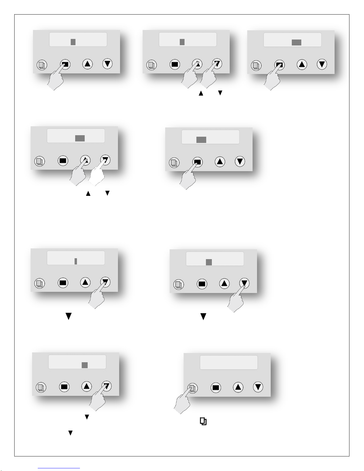
The regeneration process is completely automatic and is factory set for 12:00 AM (can be changed).
Note: No salt or chemicals are required to clean the system. As such it is typically safe to dump the
water into the septic system. However, because in every regeneration cycle, about 60 gallons of
water are used to clean the system, it is recommended that you consult a professional to ascertain
the safety of the water going into your septic system.
SAFETY PRECAUTIONS
-Follow all applicable province/state and local regulations.
-Handle the filter carefully. Do not lie on side, turn upside down, drop or drag.
CAUTIONS BEFORE INSTALLATION
Follow all plumbing codes for installation.
To operate properly, the well pump flow rate must exceed the regeneration flow rate (4.5 US GPM (17 LPM)). If
your well pump does not deliver this flow rate, do not install the unit as it will not work properly. You may need to
either change the well pump or call Rainfresh for a custom size unit that will operate within your pump
specifications.
The automatic control valve works on 110V AC. We recommend a GFI (ground fault interrupter) 120 volt outlet
within 5 feet of the filter. Extension cords are not recommended.
CAFO systems do not kill or remove bacteria or any other pathogenic microorganisms. To continuously disinfect all
the water in your house, we recommend that you install a Rainfresh UV system. Call Rainfresh for details.
For use on cold water only.
Only use thread seal tape (Teflon® tape) for fitting connections into unit. DO NOT USE pipe dope or chemical
sealants.
If water pipes are used to ground electrical system, install jumper wire (#4 gauge solid copper wire) across the unit
to maintain proper grounding of your electrical system
Protect your unit from freezing - drain the unit if freezing temperatures exist.
Do not use petroleum based lubricants on O-rings as they will cause swelling and result in water leakage.
Air Induction
Oxidizing
Iron Filter
CAFO948

3
NOTE: IF SOLDER TYPE FITTINGS ARE USED DO NOT USE torch near inlet/outlet connections. All solder joints
should be made before joining pipe to filter head.
DO NOT over-tighten metal fittings on to unit connections.
The unit should only be moved by 2 or more people due to heavy weight. Failure to do so can result in back or other
injury.
DO NOT TURN FILTER UPSIDE DOWN
How to check well pump flow rate (must be more than 5 GPM (19 LPM).
Make sure that the pressure tank is full and no one uses any water until you have finished the test.
1) Connect a hose to an appropriate outlet at the bottom of the pressure tank and put the other end into an empty
pail of known volume (e.g. a 10 gal pail)
2) Open the valve to which the hose is connected and collect water into the container. Shut off the valve as soon as
you hear the well pump come on. Measure the volume of water collected. This is the drawdown from the tank.
3) Note the time in seconds that it takes for the pump to complete a cycle from start to shut-off.
Well pump flow rate = (Volume of water collected (drawdown) ÷Time for pump cycle) x 60
EXAMPLE : If you collect 5 gal of water and the pump takes 40 seconds to complete a cycle, the flow rate is:
(5/40) x 60 = 7.5 GPM.
INSTALLATION
Electrical Requirements:
The automatic control valve requires a constant power supply - 120V/60 Hz AC. We recommend a GFI (ground fault
interrupter) outlet within 5 feet of the CAFO Filter. Extension cords are not recommended.
If water pipes are used to ground electrical system, you will need to install a jumper wire across the filter unit.
Unpacking the unit
The unit includes:
1) Main filter tank
with control
valve and
bypass valve
2) Inlet/outlet elbow fittings (2) –¾”
Male NPT with allen key ( for ease
of opening & closing bypass valve)
3) Inlet check valve
4) Drain hose (15 ft) with hose
clamp
5) AC power adapter
6) Brine check Valve

4
Unpack the unit and place it at the location where you intend to install the unit.
Stand back and look at the main media tank and make sure it is standing straight up and not tilted to one side.
Sometimes during shipment, the bottom of the tank will get knocked out of alignment and you will need to
straighten it out before starting installation. If your tank is a bit tilted, simply pick the tank up 2 –3 inches off the
floor and drop it gently but firmly down, favoring the side that needs to be adjusted to make the filter stand straight
up again.
Make sure your chosen location is fairly level, dry, and protected
from possible freezing conditions. The plastic base of the filter is
slightly adjustable to non-even floors. The filter can sit directly on the
floor, it will not corrode. DO NOT set the tanks onto make shift
platforms as this may cause the filter to topple.
The following materials can be used for installing your new system,
but it is recommended that you check your local plumbing codes.
Copper and PVC, CPVC, and PEX are the most popular.
The system has 3 connections - an inlet, an outlet, and a drain line
connection. If you are looking at the back of the unit (fig 1), the inlet is
on the left side. Warning: Make sure that you have correctly identified
the inlet of the system. REVERSING THE CONNECTIONS WILL RESULT
IN FILTER MEDIA BEING THROWN INTO YOUR HOME'S PLUMBING SYSTEM CAUSING DAMAGE TO IT AS WELL AS
THE Filter system.
You may choose not to treat the water spigots that go outside used for irrigation or sprinkler systems. You will have
to plan the job so that you cut in to feed the CAFO filter AFTER these spigots. Installing the CAFO filter after the
pressure tank is the proper location (WARNING : DO NOT INSTALL CAFO FILTER BETWEEN WELL PUMP &
PRESSURE TANK). If you intend to install a water softener to soften the water or a UV system to disinfect the water,
these should be installed after the CAFO filter (see Fig 2).
Figure 2: Piping Schematic
WATER
IN
WATER
OUT
Fig 1

5
BEFORE YOU BEGIN
INSTALLATION, CONFIRM
THE INLET AND OUTLET
OF THE UNIT AND
IDENTIFY THE SERVICE
AND BYPASS POSITIONS
OF THE VALVE (Fig 3). The
bypass valve is used to isolate the
unit from the plumbing system in
order to perform maintenance or
repairs on the unit. During normal
use the bypass valve should be in
“SERVICE” position and to isolate
it, the valve should be turned to
“BYPASS” position.
Plumbing in your CAFO Iron Filter
Turn the power off to the well pump then shut off the
main water shut off valve which should be located after
the pressure tank. Open a few faucets and empty the
pressure tank before cutting into the line. If your hot
water tank is electric, turn off the power to it to avoid
damage to the element in the tank.
The bypass valve generally comes pre-assembled. If not,
attach the bypass valve to the control valve by pushing it
in and secure it with the metal clips and screws (Fig 4).
Insert Allen key into the bypass handles and make sure
that the valve is in BYPASS position.
Firmly push the inlet/outlet elbow fittings fully into the
open end of the bypass valve and lock them in by inserting
the red locking clips into the slots (Fig 5).
For ease of installation, orient the inlet/outlet fittings in
the direction of the inlet & outlet pipes by simply rotating
them.
Use thread tape on the inlet fitting and attach the INLET
CHECK VALVE on this fitting (Fig 6) with arrow marked on
the check valve pointing towards the bypass valve.
Caution: Do not install the INLET CHECK VALVE on the
outlet fitting as that will cause malfunction of the unit.
Remove the blue locking clip on the brine fitting. Make a
mark on the open white tube of the brine check valve,
about ¾” from the open end. Push the white tube (with
brine valve attached) into the brine fitting until the mark
is flush with the fitting. Replace the blue locking clip.
Fig 4
Fig 5
Fig 3
Fig 6

6
Now plumb in the ½” flexible plastic drain tubing (included) running from the filter (elbow hose fitting) (Fig 7).
oYou can run the drain hose from the unit to the
ceiling joists (max 8 ft ceiling) and run it to the
nearest laundry tub or drain pipe. This can be ran up
overhead or down along the floor. If running drain
line more than 30 feet overhead, increasing the line
size to 3/4" will be required. Please follow your local
health dept. codes for where to run filter discharge
water. NEVER MAKE A DIRECT CONNECTION INTO A
WASTE WATER DRAIN. A PHYSICAL AIR GAP OF AT
LEAST 3" SHOULD BE USED TO AVOID BACTERIA AND
WASTEWATER TRAVELLING BACK THROUGH THE DRAIN LINE INTO THE CAFO FILTER (Fig 8).
oThere will be a fair amount of pressure on this flexible plastic drain line when the filter is in the regeneration
mode, so secure it to the drain fitting by a hose clamp. Also secure the drain tube to the wall or ceiling.
You can also use code-approved air-gap attachments available at most plumbing stores.
Before proceeding further, once again make sure that the bypass valve is in the bypass position (Fig 3)
Close all open taps and turn on the switch for the well pump.
Insert the Allen key into the inlet side of the bypass valve and turn it on only slightly and watch for leaks. Make sure
a faucet is on somewhere and that any aerator is removed to avoid clogging from loosened scale in the pipes. Leave
the bypass valve in the same position and slowly turn the main shutoff valve on all the way. If you have no leaks,
proceed to the next steps.
Connect the control valve to the AC power source (Fig 9). Manually put the
CAFO filter into the regeneration cycle by pressing the SET/REGEN button
(see page 11). NOTE : WITHOUT PERFORMING REGENERATION THIS
UNIT WILL NOT BE READY FOR SERVICE.
Turn the bypass valve slightly more into the service position to allow water
to run into the unit. You want water to initially fill the tank slowly. Once
the tank is full of water, you can open valve fully. This prevents filter
media from being pushed up into the control head by the initial surge of
water going in. Once the tank is full of water you should start to see water
flowing from the drain line. It may look somewhat discoloured at first. This
is normal. Once the water runs clear and free from air pockets, turn both
handles of the bypass valve into the full "service position". You should have a full flow to the drain at this point.
Your water may be discoloured for a day to two after initial installation or may appear milky due to small air
bubbles. This is normal. Also, it will take a few days to get all the untreated water out of your hot water tank and
you may choose to empty your hot water tank at the time of installation and clean it before letting water in from
the filter.
The system is now ready for use.
Fig 9
Fig 7
Fig 8
LAUNDRY
TUB
STANDING
PIPE
FLOOR DRAIN
OR SUMP
Min 1.5”
air gap
Min 1.5”
air gap
Min 1.5”
air gap

7
START UP & PROGRAMMING
The control valve is controlled with simple, user-friendly electronics
displayed on an LCD screen.
When power is connected, the screen will show the following information in
sequence:
1. Date & Time
2. Regeneration Days (Time interval between
regenerations)
3. Remaining Days (days left before regeneration
begins)
4. Regeneration Time (Time of day when regeneration
starts)
5. Last Regeneration Date (Last date when system
regenerated)
6. Current Flow Rate (GPM) (flow rate of water being
currently used)
7. Peak Flow Rate (GPM) (Max recorded flow rate of
the water)
The control valve has a display screen and 4 buttons
PROGRAMMING YOUR CAFO948 FILTER
The valve has 2 levels of programming –Level 1 and Level 2. The unit is factory set for your use and you do not
need to change any settings other than time and date. Please call Rainfresh before attempting to change
any values as that can affect the performance of your unit.
Level 1 PROGRAMMING
STEP 1 : Set Current Time
1. Press “ ” (MENU) for 3
seconds to unlock screen.
MENU BUTTON “ ”
The function of this key is to enter the
level one programming mode where
the valve settings can be adjusted.
SET / REGEN BUTTON “”
This button has two functions. The first is to initiate a manual regeneration by holding
the button for 3 or more seconds. The second function is while in programming mode,
pressing this key allows the user to change the value of each setting.
UP / DOWN “ ”
These buttons are used to increase or
decrease the value of the settings while
in the programming mode.
FOR VIDEO INSTRUCTIONS ON
PROGRAMMING
Visit our website
http://rainfresh.ca/how_to_videos.php
JAN/21/2015
05:27 PM
2. The display will read “Press
MENU Key for 3 sec to
unlock”.
3. After 3 seconds, the display
will beep confirming unlock
4. Press “ ” (MENU) again
and the hour value
becomes highlighted
PRESS MENU KEY
3 SEC TO UNLOCK
CURRENT TIME
05 : 27 PM

8
STEP 2 : Set Current Date
5. Press “” (SET/REGEN)
once and the highlighted
value flashes.
6. Now press “ ” (UP) or “ ”
(DOWN) key to change the
hour values to current time.
7. Press “” (SET/REGEN)
again. Hour value will be
accepted and minute value
will start flashing.
13. Press “” again and the
MONTH value flashes
CURRENT TIME
05 : 27 PM
CURRENT TIME
07 : 27 PM
CURRENT TIME
07 : 27 PM
CURRENT TIME
07 : 45 PM
8. Now press “ ” (UP) or “ ”
(DOWN) key to change the
minute value to current
time
CURRENT TIME
07 : 45 PM
9. Press “” (SET/REGEN)
again. Minute value will be
accepted and AM/PM
value will start flashing.
10. Now press “ ” (UP) or “ ”
(DOWN) key to change the value
to AM or PM
CURRENT TIME
07 : 45 AM
CURRENT TIME
07 : 45 AM
11. Press “” (SET/REGEN) again to
accept. Flashing stops & hour
value is highlighted again.
PROCEED TO STEP 2
CURRENT TIME
07 : 45 AM
12. Press “ ” to advance to
CURRENT DATE. The month
value is highlighted
CURRENT DATE
JAN/21/2012
CURRENT DATE
AUG/21/2012
14. Now press “ ”or “ ”key to
change the value to current
month

9
STEP 3: Set “Number Of People”in the house & “Feed Water Iron”
15. Press “”again. Month
value is accepted and the
DAY starts flashing
CURRENT DATE
AUG/21/2012
CURRENT DATE
AUG/15/2012
16. Now press “ ”or “ ”key
to change the value to
current day of the month
CURRENT DATE
AUG/15/2012
17. Press “”again. Date
value is accepted and the
YEAR starts flashing
CURRENT DATE
AUG/15/2015
18. Now press “ ”or “ ”key
to change the value to
current day of the month
19. Press “”again to accept. Flashing
stops & MONTH value is highlighted
again. PROCEED TO STEP 3
CURRENT DATE
AUG/15/2015
NUMBER PEOPLE
4
20. Press “ ” to advance to
NUMBER OF PEOPLE. LEAVE
THIS AT DEFAULT SETTING.
FEEDWATER IRON
05 GPG
VACATION MODE
YES NO
22 Now press “ ” key to advance to
VACATION MODE.
Press “” again to advance or press
“” to set vacation mode.
21. Press “ ” to advance to FEEDWATER
IRON. The value is highlighted. LEAVE
THIS AT DEFAULT SETTING
JAN/21/2015
05:27 PM
23. Press “ ” key to exit level 1 programming

10
Level 2 PROGRAMMING (OPTIONAL SETTINGS)
CAUTION: DO NOT CHANGE LEVEL 2 SETTINGS WITHOUT CONSULTING RAINFRESH TECHNICIAN
(1-800-667 8072). Wrongly changing the settings can result in malfunction of the unit.
NOTE : Under normal use there is no need to change the settings under level 2 programming. You can, however,
change the default settings if required.
When the Level 2 Master Programming Mode is entered, all available option setting displays may be viewed and set
as needed. Depending on current option settings, some parameters cannot be viewed or set.
To change any setting under level 2 programming
-press the “” key and the value flashes
-press the “or ” keys to change the value
-press the “” key again to accept value
-press the “ ” key to advance to the next value
The following chart indicates choices and default settings. Note: Default settings are indicated in bold letters
Use same programming method as you used in level 1 to advance and/or change values.
Bold letters indicate default settings
Parameter
Option 1
Option 2
Option 3
Option 4
Comments
1
SYSTEM
LANGUAGE
English (√)
Spanish
French
Set to French if desired. Spanish
not enabled
2
VALVE
OPERATION
Softener
Filter
Iron
Filter (√)
Leave at default setting
3
REGENERATION
MODE
Meter
Delayed
Meter
Override
Calendar
Clock (√)
Meter
Immediate
Leave at default setting
4
REGENERATION
TIME
12:00 AM
(√)
The unit is factory set to regeneration at 12:00 AM on the day of
regeneration. You can change to another time if desired.
5
CAPACITY
CALCULATION
Manual
(√)
Automatic
Leave at default setting
6
REGENERATION
DAYS
3 Days (√)
Leave at default setting. Before changing this value, contact Rainfresh
7
BACKWASH
15 (√)
Leave at default setting
8
BRINE/RINSE
45 (√)
Leave at default setting
9
RAPID RINSE
00 (√)
Leave at default setting (zero)
10
REFILL
00 (√)
Leave at default setting (zero)
11
RESTORE DEFAULT
NO (√)
Leave at default. Change only if you want to re-start programming from start
Press “ ” (MENU) for 3
seconds to unlock screen.
JAN/21/2015
05:27 PM
The display will read “Press MENU
Key for 3 sec to unlock”.
After 3 seconds, the display will
beep confirming unlock
PRESS MENU KEY
3 SEC TO UNLOCK
SYSTEM LANGUAGE
ENGLISH
Press and hold “ ” together
for three seconds to enter Level
Two Master Programming.

11
Manual Regeneration
If screen is locked, press “ MENU” for 3 seconds to unlock. To start an immediate regeneration:
Press the SET/REGEN button for 3 seconds, an option for “Delayed” or “Immediate” regeneration will
appear.
Press the SET/REGEN button again and “Delayed” will begin flashing.
Now press or buttons and “Immediate” will flash.
Press the SET/REGEN button once and then press the “MENU” button once. Valve will immediately start
manual regeneration.
OTHER FEATURES
Control Operation During a Power Failure
In the event of a power failure, the valve will keep track of the time and day for 48 hours. The programmed settings
are stored in a non-volatile memory and will not be lost during a power failure. If power fails while the unit is in
regeneration, the valve will finish regeneration after power is restored. If the valve misses a scheduled regeneration
due to a power failure, it will queue regeneration at the next regeneration time once power is restored.
New Sounds
You may notice new sounds as your filter operates. The regeneration cycle lasts approximately 20 minutes. During
this time, you may hear water running intermittently to the drain.
Manual Bypass
In the case of emergency, such as a leak, you can isolate your filter system from the water supply using the bypass
valve located at the back of the control (see Fig 3). To resume filtered water service, open bypass valve by rotating
the knobs counterclockwise.
MAINTENANCE
The CAFO948 filter does not require any routine maintenance except ensuring that it regenerates regularly. There
are no filters or parts to be replaced. Typically, after a few years of service (5-7), you may notice that some iron is
present in filtered water. At this time you will need to replace the filter media in the unit, which can be purchased
from Rainfresh. Please call customer service at 1800-667-8072.
Care of your CAFO948 Iron filter
To retain the attractive appearance of your new filter, clean occasionally with mild soap solution. Do not use
abrasive cleaners, ammonia or solvents. Ensure that there is no dust or debris on the bypass valve.
Winterizing the system
If the unit is to be winterized, the best way is to close the by-pass valve and unscrew the 2 screws adjacent to the by-
pass valves that hold the unit and the by-pass valve together, and carry the unit to a place where it will not be
subject to freezing temperatures.

12
TROUBLESHOOTING
Please review the following troubleshooting guide before calling customer service.
If you are unable to resolve the problem using the guide below, please call customer service at 1800 667
8072 (Mon to Fri 8:30 AM to 5 PM EST)
Please have your receipt & model number ready before you call. Customer service may
request digital pictures of your installation in order to help troubleshoot the unit.
ISSUE
POSSIBLE CAUSE
SOLUTION
A. No water flowing into
filter unit
1. Inlet check valve installed in
reverse
1. Install check valve with arrow pointing
towards bypass valve (see Fig 6)
B. Unit does not
regenerate
1. No power supply
2. Defective circuit board
3. Bypass valve closed
1. Check power supply & re-set time of day
2. Replace faulty parts
3. Open bypass valve (see Fig 3)
C. Filter does not seem to
be working as there is
iron in filtered water
1. Power supply unplugged
2. Bypass valve is closed
3. Leak between valve and riser
tube
4. Internal valve leak
5. Air leak in brine check valve
or inlet check valve
6. Supply water pH too low
1. Plug in control valve to power supply
2. Open bypass valve
3. Check if riser is cracked or O-ring is
damaged. Replace faulty parts
4. Replace valve seals, spacer and piston
assembly
5. Push brine check valve fully into fitting or
replace. Replace inlet check valve
6. Install pH neutralizing filter (Call Rainfresh)
D. Low water pressure
1. Not enough water flow from
pump to regenerate unit
properly
2. Inlet of control valve plugged
due to dirt
1. Replace pump to correct size. May need to
replace filter sand as well. Remove any
flow limiting devices before unit
2. Clean control valve inlet
E. Filter media in drain line
1. Incorrect or missing drain line
flow control (DLFC)
1. Check and replace DLFC
F. Filter media in plumbing
lines or water is coming
out grey or very
discoloured
1. You have reversed the
inlet/outlet of the unit
1. See fig 1 for correct inlet/outlet and plumb
correctly. You will need to flush all your
plumbing lines and may need to top up the
sand as well
G. Unit cycles continuously
1. Defective circuit board
1. Replace faulty parts
H. Water flows to drain
continuously
1. Valve settings incorrect
2. Internal leak
1. Check valve settings
2. Replace seals, spacer & piston assembly
I. Filter is leaking between
the bypass valve and
control valve
1. O-rings pinched or damaged
Check the metal adapter clips holding the 2
components together and tighten if necessary.
Replace O-rings as required
J. Filter is always flashing
through different pieces
of information
This is normal
No action required
K. I am having difficulty
accessing level 2
programming?
Unlock the screen by pressing and holding the
menu button for 3 seconds. Press and hold
both up and down arrows until the system
language appears. See video at
http://rainfresh.ca/how_to_videos.php
L. My display screen is
blank
1. Power cord may be unplugged
from either adapter or receptacle
2. Defective circuit board
1. Re-connect power cord
2. Call Rainfresh to receive new circuit board
with replacement instructions

13
VALVE BODY

14
POWER HEAD

15
PARTS LIST
To order replacement parts:
Call 1800 667 8072
Monday to Friday
8:00 AM to 5 PM EST.

16
Limited Warranty:
This CAFO948 System is warranted to the original
Consumer purchaser for a period of one (1) year, from the
date of purchase, against defects in materials or
workmanship. The electronic controls and mineral tank are
warranted for 5 and 10 years respectively against defects in
materials or workmanship. The company's obligation under
this warranty shall consist of repair or replacement, at its
option, of any part found by company inspection to be
defective, provided that the product has not been misused,
abuse, altered or damaged by Consumer with respect to
the original installation, as determined by the company.
This warranty will not apply if feed water does not meet
specifications of this system. This limited Warranty applies
only to a unit when returned to the Warrantor at the
owner’s expense and in accordance with shipping
instructions received from the Warrantor. This warranty
does NOT cover, and is intended to exclude, any liability on
the part of Envirogard for any incidental damages,
consequential damages, labour charges or any other costs
incurred in connection with the purchase, installation, use,
maintenance or repair of the system whether under this
warranty or any other warranty implied by law. Some
provinces/states do not allow the exclusion of incidental or
consequential damages, so the above limitation or
exclusion may not apply to you. This warranty gives you
specific legal rights and you may also have other rights,
which vary from province/state to province/state. This
warranty applies only to CAFO948 systems purchased in
Canada.
Envirogard Products Limited
446 Major Mackenzie Drive East,
Richmond Hill, ON L4C 1J2, Canada
Tel : (905) 884 9388 Helpline: 1800 667 8072
Web: www.rainfresh.ca
© COPYRIGHT . ENVIROGARD PRODUCTS LIMITED 2017 . ALL RIGHTS RESERVED
Aug 2017
DESCRIPTION
1
Riser
2
Media Tank –9”x 48”
3
Filter media (1 cu ft)
4
Bottom Distributor
5
Power adapter (110V)
6
Inlet check valve
1
2
3
4
5
6
To order replacement parts:
Call 1800 667 8072
Monday to Friday
8:00 AM to 5 PM EST.
Other manuals for CAFO 948
1
Table of contents
Other Rainfresh Water Dispenser manuals
Popular Water Dispenser manuals by other brands

DanPure
DanPure LUXE 75 user manual

Hellenbrand
Hellenbrand ProMate Series owner's manual

Ecodyne Water Systems
Ecodyne Water Systems EP 6130 Installation, operation, maintenance & repair parts

MUHLER
MUHLER WD-11ED instruction manual

AmeriWater
AmeriWater CW330 Series Operation & installation manual

Tong Yang
Tong Yang WPU-8900C/F Safety instruction