Raisecom RC904-V35FE1-BL User manual

RC904-V35FE1-BL
V35 to fractional E1balanced interface
converter
User manual
REV.C
Raisecom technology Co., Ltd
(10/2005)

Raisecom Technology Co., Ltd
1
1. Cautions
Please read the following notices carefully before installing
and using the device, Raisecom does not respond to any loss
that caused by violating safety notices.
RC904-V35FE1-BL provides standard V35 synchronous data
interface that is compliant with ITU norm. V35 cable must be
connected to the device before powered on. To avoid
damaging V35 data interface hot-swap of V35 cable is strictly
forbidden. RC904-V35FE1-BL also provides standard E1 port
that is compliant with ITU-T norm, to avoid damaging E1 port
there must be grounding protection and the voltage between
the two ends shielded layer of coaxial cable cannot be too
high.
RC904-V35FE1-BL is an integrated device that has precise
elements, please avoid violent shakes and impacts, and do not
disassemble or maintain the device yourself. If it is required,
please do it under the guide of our technical staff following in
the steps of anti static. Please contact us if there is any need.
There must be grounding protection for the sake of safety; do

Raisecom Technology Co., Ltd
2
not disassemble the device yourself, we regard it as you
waiver your rights of repair guarantee.

Raisecom Technology Co., Ltd
3
Contents
1. Cautions .............................................................................................................. 1
2. Overview ............................................................................................................. 4
2.1. Introduction .................................................................................................. 4
2.2. Main feathers ............................................................................................... 4
2.3. Device serial number and pair use explanation:........................................... 5
3. Parameters.......................................................................................................... 6
3.1. V35 interface characteristic .......................................................................... 6
3.2. E1 interface characteristic ............................................................................ 6
3.3. Cable type .................................................................................................... 6
3.4. Power consumption...................................................................................... 6
3.5. Dimensions .................................................................................................. 7
3.6. Environment requirements ........................................................................... 7
4. How to use .......................................................................................................... 8
4.1. Front panel ................................................................................................... 8
4.2. DIP-Switch Setting ..................................................................................... 10
5. Installation & Preparation .................................................................................. 18
5.1. Installation preparation ............................................................................... 18
6. Q & A ................................................................................................................. 19
7. Appendix How to make cable ............................................................................ 21

Raisecom Technology Co., Ltd
4
2. Overview
2.1. Introduction
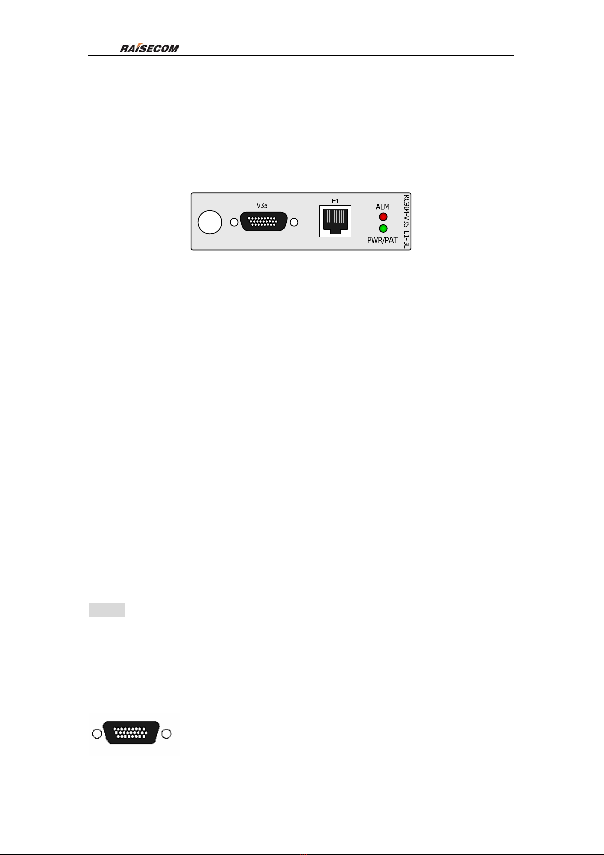
RC904-V35FE1-BL V.35 to E1 interface module converter extends
transmission distance of V35 data by utilizing long haul transmission of E1 line.
They provide a solution for remote connection of routers, and are very common
interface converter devices in WAN organizing.
RC904-V35FE1 provides one V.35 interface and one E1 interface to support
N×64Kbps(N=1~31)fractional E1 transmission.
RC904-V35FE1-BL series are module devices and can be installed in
Raisecom RC002-16 16 slots chassis, RC002-4 4 slots chassis and RC001-1
single slot chassis, SNMP network management is available and remote
device status also can be inquired.
2.2. Main feathers
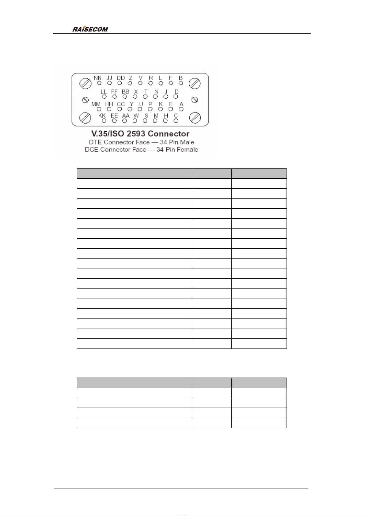
zProvide a DCE interface for V35 synchronous data and is compliant with
ITU norm.
zProvide a 120Ωbalanced E1 interface compliant ITU-T G.703, and the
longest transmission distance is 1800m.
zUtilize ITU-T G.704 frame format to adjust the bandwidth of V35 interface.
zDiversified E1 cable alarms provide local and remote alarm index.
zSupport local and remote loop-back function for error code test.
zSupport both E1 fractional frame format and transparent frame format, and
in fractional mode all the time slots are available for configuration.
zProvide 3 kinds of clock mode: master clock (inside timing), slave clock
(follow E1 line for timing), V35 clock (follow V35 line for timing).
zThe remote device can detect the local device automatically to synchronize
time slot configuration when the devices are pair used in fractional mode.
zInside error code test module is available for variable loop back tests to
diagnose faults.
zBoth PCM30 and PCM31 are available in fractional mode, and CRC4
function is auto-adapted.
zSupport adjustment function of V35 Rx data phase.
zSupport fault pass through function, and the line fault can be tested from
the V35 interface.
zUtilize large scale ASIC chip and 4 layers of PCB, low power consumption
and high reliability.

Raisecom Technology Co., Ltd
5
2.3. Device serial number and pair use explanation:
Types of RC903/904-V35FE1 series converters:
Type
Description
RC904-V35FE1-BL Local/user module
,
one V35 port
(
HDB26 male
),
one 120
Ω
RJ45 port
,
support local
network management
RC904-V35FE1 Local/user module
,
one V35 port
(
HDB26 male
)
, one pair 75
Ωcoaxial ports,
support
local network management
RC903-V35FE1 Standalone device
,
one V35 port
(
M34 female
),
one pair 75
Ω
BNC
coaxial ports
,
one120
Ω
RJ45 port.
The shadow part is the device type this manual describes. RC903-V35FE1
standalone device includes
RC903
-V35FE1-AC, RC903-V35FE1-DC, and AC,
DC stand for the power supply type.
RC903/904-V35FE1 series converters can communicate with nearly all the
same/approximate function products.

Raisecom Technology Co., Ltd
6
3. Parameters
3.1. V35 interface characteristic
Physical characteristics: Complies with V.35 interface standard
Connector type:ISO 2593 female connector (34 pin female)
Working mode:DCE(can be connected with other types of DCE
devices)
Interface bit rate:V.35 interface rate is N×64Kbps(N=1~31)at E1
fractional mode;
V.35 interface rate is 2048Kbps at E1 transparent
pattern
3.2. E1 interface characteristic
Nominal rate:2048Kbps
Interface coding:HDB3
Interface impedance:120Ω(balanced)
Connector:RJ-45connector
Electrical feature:Compliant with ITU-T G.703
Other feathers:Transfer feature, jitter tolerance compliant with ITU-T
G.823, G.724
3.3. Cable type
When connect HDB26 interface with DTE devices such as routers, affixing
CBL-V35-HDB26M/M34F cable provided by Raisecom is required. If there is
not enough cable, you can order from Raisecom.
When connect HDB26 with other company DCE devices, you need to order
cross CBL-V35-HDB26M/M34M-X cable from Raisecom. And Raisecom does
not provide this kind of cable affixed with the device. You must tell us the cable
length, if not we will provide 2m cable.
22WAG and 24WAG are both available for E1 cable.
3.4. Power consumption
Power consumption: ≤5W

Raisecom Technology Co., Ltd
7
3.5. Dimensions
91mm (W)*25mm (H)* 178mm (D)
3.6. Environment requirements
Temperature: 0 ~45℃
Humidity: ≤90%(25℃)

Raisecom Technology Co., Ltd
8
4. How to use
4.1. Front panel
Front panel view
zPower/error code test indicator light:
PWR/PAT Green/Yellow:
Green,device power supply works normal;
Yellow,when doing the error bit test: there is no error bit; when there are error
bits, this light will turn Green for 1 second at least.
zAlarm indicator light:
ALM Red/Yellow:
Red(ON) LOSalarmoflocalE1Rx.
Red (Flashing) LOS alarm of remote E1 Rx.(only in E1 fractional
mode)
Yellow (ON) In fractional mode, there are local E1 Rx alarms: AIS
alarm, LOF alarm, LOMF alarm, CRC4 error alarm or
Coding Violation alarm;
In transparent mode, there are local E1 Rx alarms:
AIS alarm or Coding Violation alarm
Yellow (Flicking) There are remote Rx alarms: AIS alarm, G704 LOF
alarm, G704 LOMF alarm, CRC4 alarm and Coding
Violation alarm (only when pair used the devices and
in E1 fractional mode)
Note:
RC904-V35FE1-BL supports CRC4 auto-adapt function, when there is CRC4
information in Rx data, it will enable CRC4 function and there will be alarm if
there is CRC4 error; when there is no CRC4 information in Rx E1 data, CRC4
will be disabled and there will not be CRC4 error alarm.
zV.35 interface:
The left figure is a HDB26 connector, and Raisecom ISO2593
cable converter connector is required.

Raisecom Technology Co., Ltd
9
The left figure is a
standard V.35 interface
ISO 2593 connector,our
devices utilizes DCE
Connector Face – 34 Pin
Female connector and
can be connected to
standard DTE cable.
Interface definition:
I-IN;O-OUT
Signal name IN/OUT Pin number
Chassis Ground — CGND - A
Signal Ground — GND - B
Receive Data (A) — RD(A) O R
Receive Data (B) — RD(B) O T
Receive Timing (A) — RCK(A) O V
Receive Timing (B) — RCK(B) O X
Send Data (A) — TD(A) I P
Send Data (B) — TD(B) I S
Send Timing (A) — TCK(A) O Y
Send Timing (B) — TCK(B) O AA
Terminal Timing (A) — SCTE(A) I U
Terminal Timing (B) — SCTE(B) I W
Request to Send — RTS I C
Clear to Send — CTS O D
Data Set Ready — DSR O E
Data Carrier Detect — DCD O F
Data Terminal Ready — DTR I H
zE1 interface:
E1 interface is RJ45 connector:
Signal name IN/OUT Pin number
TX+ O 1
TX- O 2
RX+ I 4
RX- I 5

Raisecom Technology Co., Ltd
10
4.2. DIP-Switch Setting
There are six 8-bit DIP-switches (as the above figure): SW1, SW2, SW3, SW4,
SW5 and SW6, and top indicates ON, below indicates OFF when the left is the
first bit and the right is the eighth bit.
There is a 2-bit DIP-switch SW7.
The locations of the six DIP-switches on module are in the following figure, and
you must set the DIP-switches before install the module into the chassis.
zTime slot configuration DIP-switches SW1 to SW4:
Time slot configuration switches are: SW1, SW2, SW3 and SW4
In the following table “√” indicates ENABLE and “×” indicates DISABLE.
SW1 definition(Default status: OFF)
1
st bit 2nd bit 3rd bit 4th bit 5th bit 6th bit 7th bit 8th bit
Definition
Frame
format
TS1 TS2 TS3 TS4 TS5 TS6 TS7
ON Fractional √√√√√√√
OFF Transparent × × × × × × ×
SW2 definition(Default status: OFF)
1
st bit 2nd bit 3rd bit 4th bit 5th bit 6th bit 7th bit 8th bit
Definition TS8 TS9 TS10 TS11 TS12 TS13 TS14 TS15
ON √√√√√√√√
OFF × × × × × × × ×

Raisecom Technology Co., Ltd
11
SW3 definition(Default status: OFF)
1
st bit 2nd bit 3rd bit 4th bit 5th bit 6th bit 7th bit 8th bit
Definition TS16* TS17 TS18 TS19 TS20 TS21 TS22 TS23
ON √√√√√√√√
OFF × × × × × × × ×
SW4 definition(Default status: OFF)
1
st bit 2nd bit 3rd bit 4th bit 5th bit 6th bit 7th bit 8th bit
Definition TS24 TS25 TS26 TS27 TS28 TS29 TS30 TS31
ON √√√√√√√√
OFF × × × × × × × ×
Note:
If SW1-1 is configured as transparent mode, DIP-switches from TS1 to TS31
are invalid;
If SW1-1 is configured as fractional mode, DIP-switches from TS1 to TS31 are
valid and cannot be OFF all. There must be some time slots using otherwise it
cannot be fractional mode.
If SW3-1(TS16) is enabled, the device works in PCM31 frame format;
If SW3-1(TS16) is disabled, the device works in PCM30 frame format.
zFunction select DIP-switch SW5:
The function select DIP-switch is SW5
In the following table “√” indicates ENABLE and “×” indicates DISABLE.
SW5 definition
1
st bit 2nd bit 3rd bit 4th bit 5th bit 6th bit 7th bit 8th bit
Definition Timing
Clock 1
Timing
Clock 2
TS_FLOW
Time slot
follow
switch
BERT
Error bit
test
RX CLK
Phase
ALOOP
Local V35
Loop-back
test switch
DLOOP
Local E1
Loop-back
test switch
RLOOP
Remote
E1
Loop-back
test switch
ON * * √√Positive √√√
OFF * * × × Negative × × ×
1. 1st bit and 2nd bit of SW5: clock mode select switch Timing1 and
Timing2(default status: OFF)
The working clock mode is codetermined by both 1st bit and 2nd bit of SW5 as in
the following table:
SW5 1st bit SW5 2nd bit Clock mode
OFF OFF
Master clock mode(Internal clock)
OFF ON
V.35 terminal clock mode(follow V35
interface clock)

Raisecom Technology Co., Ltd
12
ON OFF N/A
ON ON
Slave clock mode(follow E1Rx line clock)
2. 3rd bit:Time slot auto-follow function switch TS_FLOW(default status:
OFF)
3rd bit Time slot
auto-follow function
switch
ON Enable
OFF Disable
The following conditions must be satisfied to realize time slot auto-follow
function:
(1)Same series devices must be pair used and in point-to-point topology.
(2)In E1 line there is no PCM device that the Sa bit is occupied.
(3)Neither of the two ends devices can be configured in transparent mode.
Local device must be configured in fractional mode at first! Set SW1-1
ON, and DIP-switches from TS1 to TS31cannot be OFF all.
(4)When set local device in slave clock mode, time slot auto-follow function
will enable automatically.
After satisfy the above conditions, set the time slot auto-follow function switch
ON, and enable the auto-follow function, then local time slots and frame format
(PCM30/PCM31) will follow that of remote device.
3. 4th bit:error code test switch BERT(default status: OFF)
SW5 4th bit
ON Enable inside error
code test
OFF Disable inside error
code test
Inside the device there is an error code test unit that generates pseudo-random
sequences in 2E15-1 Std format, and transmits the sequences to E1 line. The
sequences can be configured to transmit in different data channels, then users
can configure loop-back mode for the device checking the return sequences.
The PWR/PAT indicator light will display test result. When there is error code,
the PWR/PAT indicator will turn green for 1 second at least, and will turn yellow
if there is no more error code.
When enable the error code test function (V35 service will be interrupted), the
device will send test sequences to data channel, and the function is available in
both fractional and transparent mode.
Note:
Error code test function can be used for variable tests along with multiple

Raisecom Technology Co., Ltd
13
loop-back. When enable ALOOP local V35 loop-back test function, cable is
available for simulating local loop-back. And if PWR/PAT is yellow (ON), there
is no error code. When enable RLOOP remote E1 loop-back test, the test
sequences will be transmitted for a whole process.
4.5th bit:RX CLK phase select DIP-switch(default status: OFF)
SW5 5th bit
ON Negative RX CLK
phase
OFF Positive RX CLK
phase
This DIP-switch is for different routers which data phase may be different.
When set the RX CLK phase positive, RC904-V35FE1-BL can communicate
with Cisco series V35 interfaces.
RX CLK positive:RD signal is updated by RX CLK falling edge.
RX CLK
RD
RX CLK negative:RX CLK rising edge updates RD signal
RX CLK
RD
Note: the TX CLK and TD phase is auto-adjust, and does not need to
configure.
5.6th , 7th, and 8th bits:loop-back test switches(default status: OFF)
The 6th, 7th, and 8th bits can control 3 types of loop-back tests, please be
attention that only one kind of loop-back test can enable at one time, two or
more loop-back tests are not allowed to enable at one time.
ALOOP local V35 interface loop-back for test V35 cable local device is as the
following figure:
DLOOP local E1 interface loop-back for test E1 line and E1 interface
parameters (e.g. whether local time slots are same with those of remote device)
is as the following figure:
RLOOP remote E1 interface loop-back:
DTE
or V.35 BERT Local device
Master clock
E1V.35
DTE
or V.35 BERT
Local device
Master clock
E1V.35
DTE
or V.35 BERT
Local device
Remote
device
E1V.35
DTE
or V.35 BERT

Raisecom Technology Co., Ltd
14
Remote loop-back function is only available when RC903/904-V35FE1 (REV.C)
series products are pair used and in fractional mode. Local V35 cable, local
device, E1 line and remote device all can be tested. Note that the two ends
device clock must be the same before testing.
zFunction select DIP-switch SW6:
SW6 definition(default status: OFF)
1
st bit 2nd bit 3rd bit 4th bit 5th bit 6th bit 7th bit 8th bit
Definition Fault
pass
through
Reserved Reserved Reserved N/A
ON Enable
OFF Disable Default Default Default
1. 1st bit:fault pass through DIP-switch
1st bit Fault pass
through
ON Enable
OFF Disable
When enable fault pass through function, alarms of optical Rx and Tx will be
passed through to DCD and CTS signal of V35 interface; when disable fault
pass through function, DSR, DCD and CTS will always valid.
If there are local alarms of RC904-V34FE1-BL, there will be fault of RC904,
and then DCD signal of V35 interface will be shutdown, and DTE device will
response.
If there are remote alarms of RC904-V34FE1-BL, there will be fault of optical
Tx, and then CTS signal of V35 interface will be shutdown, and DTE device will
response.
Local DSR signal will always valid after powered on.
2. 2nd, 3rd, 4th bits :reserved
These DIP-switches are reserved for test and should be OFF in normal.
3. 5th, 6th, 7th and 8th bits: no meaning
These DIP-switches are no meaning.
zE1 interface Long/Short Haul select:
z
SW7 is E1 coaxial interface grounding switch
1 2
ON
OFF
ON

Raisecom Technology Co., Ltd
15
1st 2
nd Definition
ON ON Long Haul -36dB(factory default)
OFF ON Long Haul -43dB
ON OFF Short Haul -15dB
OFF OFF Gain Mode
Long Haul -36dB:
Equalizer detects the input wave and compensates 36dB at most to adjust
input E1 signal, and this function is used for cable loss (frequency), but not flat
loss (resistive);
Long Haul -43dB:
Equalizer detects the input wave and compensates 43dB at most to adjust
input E1 signal, and this function is used for cable loss (frequency), but not flat
loss (resistive);
Short Haul -15dB:
Equalizer detects the input wave and compensates 15dB at most to adjust
input E1 signal, and this function is used for cable loss (frequency), but not flat
loss (resistive);
Gain Mode:
Equalizer detects the input wave and compensates 29dB at most to adjust
input E1 signal, and this function is used for flat loss (resistive), cable loss
(frequency).
The relationship between hardware configuration DIP-switches and software
configuration
The relationship is in following table:
Hardware switch Whether software can
configure
SW1~SW4 Yes
SW5 Yes
SW6 No
Basic connection topology
The following topologies are just for reference, and users can organize your
network according practice. The following topologies are RC903-V35FE1
examples.
zPoint-to-point “master-slave clock” mode

Raisecom Technology Co., Ltd
16
As in above figure, when connect to the V.35 interface of Routers or other
equipments in point-to-point pattern; Routers need to work at DTE mode. For
convenience of installation and preparation, local converter can work in master
clock mode and remote converter in slave clock mode, the clock source should
be in local converter.
When use “Master clock — Slave clock” connection structure, if DXC and
MUX equipments are in series in E1 line, the DXC, MUX and remote converter
should be at slave clock mode (follow E1 link clock).
zPoint-to-point “Terminal clock — Slave clock” topology:
When remote DTE equipments must follow local DTE equipments output clock,
namely TX CLOCK of local DTE is internal clock source, local converter is
configured in terminal clock mode, and local converter in slave clock mode,
V.35 interface of local DTE equipment must configure clock frequency.
When use “Terminal clock — Slave clock” connection topology, if there are
DXC and MUX equipments in series in E1 link, then DXC, MUX and remote
converter should be in slave clock mode (follow E1 link clock).
zPoint-to-point fractional E1 mode “Slave clock — Slave clock”
/DCE

Raisecom Technology Co., Ltd
17
structure
When use slave mode at both sides, there must be clock source provided by
DXC, MUX or other PCM fractional E1 equipments in E1 line, and only one
clock source can exist in whole E1 line.
zExtending topology
Connect with other factory product and not pare used.
If remote routers use E1 interface, parameters of E1 line must first be
confirmed, such as fractional/transparent E1, PCM30/31, CRC enable/disable,
relationship of clock, bandwidth distribution and time slots occupied etc. If any
one of those does not match the setting of the converter’s, there will be
problems in connection.
In this case, if both ends equipments work in fractional E1 mode, the clock
relationship can be easily omitted. Should first make sure that, in witch
equipment the clock source is, then the equipment at other end should follow
E1 link clock.

Raisecom Technology Co., Ltd
18
5. Installation & Preparation
5.1. Installation preparation
zMake sure that the V35 cable you use matches the connected device.
zWhether the device has damage
zConfigure the DIP-switches before installing if there is no network
management software.
zSoftware configuration privilege is high than that of hardware except fault
pass through function.
Notice when powered on
zV.35 interface is strictly forbidden to hot-swap when powered on
z-48V DC power supply,we suggest first connect the grounding protection
PGND(middle part of DC outlet), Note, inverse connection of positive and
negative polarity is forbidden.
Deployments
zIn equipment room, this must be kept clean and with air-conditioning
devices.
zRecheck configuration switches and other parameters.
Test of connection
zMake sure that no alarm in local equipment
zCheck if local DTE equipment can communicate with remote equipment
If the data communication cannot be processed, then check:
1.Use the 3 types of loop-back tests to check whether the device works
normal.
2.If there is packet loss of routers, RX CLK phase may need to adjust, or
there are some error codes in E1 line.
3.If the ALM flicks not periodically, E1 cable may have problems, and please
check E1 cable.
After the above steps, if there is still the problem please contact sellers for
technical support.

Raisecom Technology Co., Ltd
19
6. Q & A
If there are any problems during installation and operation, please try to solve
them by the following suggestions. If they cannot be solved, please contact
distributors for help.
1. Power indicator (PWR) OFF
Answer:Please check if there is any fault with power supply
2. Yellow ON, after connection coaxial cable in transparent mode.
Answer: in transparent mode, if E1 receives AIS signal, the ALM will turn
yellow (ON). If you can make sure that the line is normal, maybe: the
remote V35 interface of remote device does not connect to routers, remote
router is powered off or remote V35 interface of router is shutdown. In
some case, this device can communicate with some routers normally even
if the ALM in yellow (ON) or turns yellow at interval, that is because remote
router V35 interface outputs AIS signal in idle status. If it does not effect the
communication, we hope our customers can understand.
3. PWR/PAT turns green and yellow alternately when enable loop-back
function and use BERT.
Answer:It will take 3 to 5 seconds for the device initialization, and during
this time the status of indicator lights is not normal.
4. When there is conflict between network management software and
hardware DIP-switches, which privilege is higher?
Answer: CPU only reads DIP-switches configuration once, thereafter it will read
network management configuration. Please be attention that software
cannot configure fault pass through.
5. How to deal with serious packet loss?
Answer:The followings maybe the reason:
Clock mode configuration is not correct; there may be more than one
clock source.
Check the V35 interface status of router, if there is output/input data
error, the RX CLK phase of local or remote side need change.
If there is coding violating of coaxial cable, it maybe caused by
common grounding or virtual shout-cut. You can enable the error code
test function to check the cable.
6. Compatibility with other factories products
Answer: this device can interoperate with products with similar function of
other brands, and can interoperate with Routers with fractional E1 interface,
Table of contents
Other Raisecom Media Converter manuals

Raisecom
Raisecom RC906-FXE1-M User manual

Raisecom
Raisecom RC953-4FE E1T1 Series User manual

Raisecom
Raisecom RC952-FEE1-BL User manual

Raisecom
Raisecom RC513 User manual

Raisecom
Raisecom RC315 User manual

Raisecom
Raisecom RC552-FE User manual

Raisecom
Raisecom RC902-FE4E1-BL User manual

Raisecom
Raisecom RC905-EE1 User manual