9
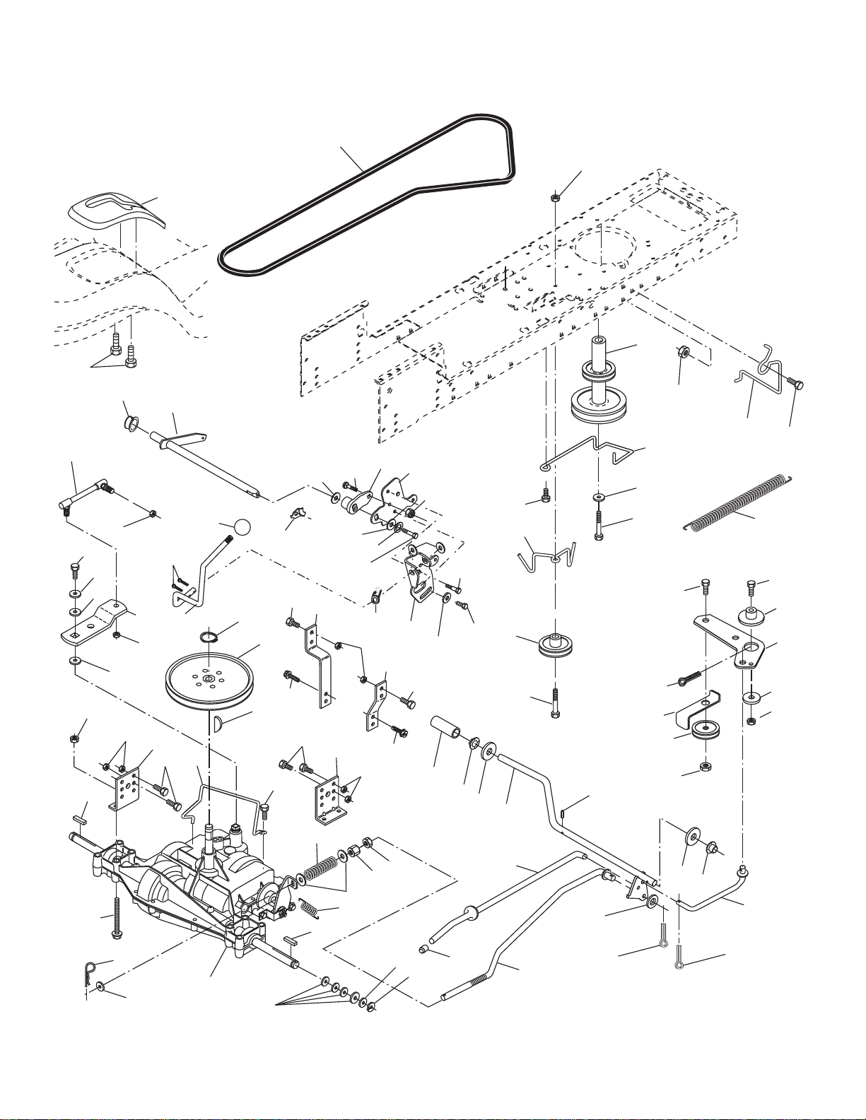
TRACTOR - - MODEL NUMBER CO15538LT (96012007403), PRODUCT NO. 960 12 00-74
DRIVE
KEY PART
NO. NO. DESCRIPTION
KEY PART
NO. NO. DESCRIPTION
1 - - - - - - - Transaxle DANA D6800-5 (Order
parts from transaxle manufacturer)
2 532 14 66-82 Spring Return Brake T/a Zinc
3 532 12 36-66 Pulley Transaxle 18" tires
4 812 00 00-28 Ring Retainer # 5100-62
5 532 12 15-20 Strap Torque 30 Degrees
6 817 06 05-12 Screw 5/16-18 x 3/4
8 532 19 27-06 Rod Shift Fender Adjust Lt
10 876 02 04-16 Pin Cotter 1/8 x 1 Cad
11 532 10 57-01 Washer Plate Shf 388 Sq Hole
13 874 55 04-12 Bolt 1/4-28 unf Gr. 8 W/Patch
14 810 04 04-00 Washer Lock Hvy Helical
15 874 49 05-44 Bolt Hex FLGHD 5/16-18 Gr. 5
16 873 80 05-00 Nut Lock Hex w/ins 5/16-18
18 874 78 06-16 Bolt, Fin Hex 3/8-16 unc x 1 Gr. 5
19 873 80 06-00 Nut Lock 3/8-16 unc
21 532 10 69-33 Knob
22 532 13 08-04 Rod Brake Blk Zinc 26 840
24 873 35 06-00 Nut Hex Jam 3/8-16 unc
25 532 10 68-88 Spring Rod Brake 2 00 Zinc
26 819 13 13-16 Washer 13/32 x 13/16 x 16 Ga.
27 876 02 04-12 Pin Cotter 1/8 x 3/4 Cad
28 532 17 57-65 Rod Brake Parking LT/YT
29 532 07 16-73 Cap Brake Parking
30 532 17 49-73 Bracket Mtg Transaxle
32 874 76 05-12 Bolt Hex Hd 5/16-18 unc x 3/4
34 532 17 55-78 Shaft Asm Pedal Foot
35 532 12 01-83 Bearing Nylon Blk 629 Id
36 819 21 16-16 Washer 21/32 x 1 x 16 Ga.
37 532 12 49-63 Pin Roll 3/16 x 1"
38 532 17 91-14 Pulley Composite Flat
39 872 11 06-22 Bolt RDHD 3/8-16 unc x 2-3/4 Gr. 5
41 532 17 55-56 Keeper Belt Flat Idler
47 532 12 77-83 Pulley Idler V Groove Plastic
48 532 15 44-07 Bellcrank Asm
49 532 12 32-05 Retainer Belt Style Spring
50 872 11 06-12 Bolt Carr. Sh. 3/8-16 x 1-1/2 Gr. 5
51 873 68 06-00 Nut Crownlock 3/8-16 unc
52 873 68 05-00 Nut Crownlock 5/16-18 unc
53 532 19 96-52 Link Clutch
55 532 10 57-09 Spring Return Clutch 6 75
56 817 06 06-20 Screw 3/8-16 x 1-1/4
57 532 40 16-03 V-Belt Ground Drive
62 532 12 48-72 Cover Pedal Blk Round
63 532 17 54-10 Engine Pulley
64 532 17 39-37 Bolt Hex
65 810 04 07-00 Washer Lock Hvy Hlcl Spr 7/16
66 532 15 47-78 Keeper Belt Engine Foolproof
69 532 14 24-32 Screw Hex wsh HiLo 1/4 x 1/2 unc
70 532 13 46-83 Guide Belt Mower Drive RH
75 532 12 17-49 Washer 25/32 x 1 1/4 x 16 Ga.
76 812 00 00-01 E-ring #5133-75
77 532 12 35-83 Key Square 2 0 x 1845/ 1865
78 532 12 17-48 Washer 25/32 x 1-5/8 x 16 Ga.
79 532 12 50-96 Key Woodruff #9 3/16 x 3/4
80 532 13 14-88 Arm Shift
81 532 16 55-94 ShaftAsmCrossTaperedPMST/20
82 532 16 57-11 Spring Torsion T/a
83 819 17 12-16 Washer 17/32 x 3/4 x 16 Ga.
84 532 16 62-29 Link Transaxle Dana/18" Zinc
85 532 15 03-60 Nut Lock Center 1/4 - 28 FNTHD
89 532 19 58-61 Console Shift STLT
96 532 12 47-88 Retainer Spring 1"
112 819 09 12-10 Washer 9/32 x 3/4 x 10 Ga.
113 532 12 72-85 Strap Torque LT
116 872 14 06-08 Bolt Rdhd Sq Neck 3/8-16 x 1
120 873 90 06-00 Nut Lock Flg. 3/8-16 unc
150 532 17 54-56 Spacer Retainer
151 819 13 32-10 Washer 13/32 x 2 x 10
156 532 16 60-02 Washer Srrted 5/16ID x 1.125
158 532 16 55-89 Bracket Shift Mount
159 532 18 39-00 Hub Tapered Flange Shift Lt
161 872 14 04-06 Bolt Rdhd Sqnk 1/4-20 x 3/4
162 873 68 04-00 Nut Crownlock 1/4-20 unc
163 874 78 04-16 Bolt Hex Fin 1/4-20 unc x 1 Gr. 5
165 532 16 56-23 Bracket Pivot Lever
166 817 49 05-10 Screw 5/16-18 x 5/8
168 532 16 54-92 Bolt Shoulder 5/16-18 x .561
169 532 16 55-80 Plate Fastening
170 532 18 74-14 Keeper Belt Transaxle Gear
197 532 16 96-13 Nyliner Snap-In
198 532 16 95-93 Washer Nyliner
202 872 11 06-14 Bolt RdHd 3/8-16 unc x 1-3/4 Gr. 5
212 532 14 52-12 Nut Hexflange Lock
NOTE: All component dimensions given in U.S. inches
1 inch = 25.4 mm