manuals.online logo
Brands
  1. Home
  2. •
  3. Brands
  4. •
  5. RamonSoler
  6. •
  7. Bathroom Fixture
  8. •
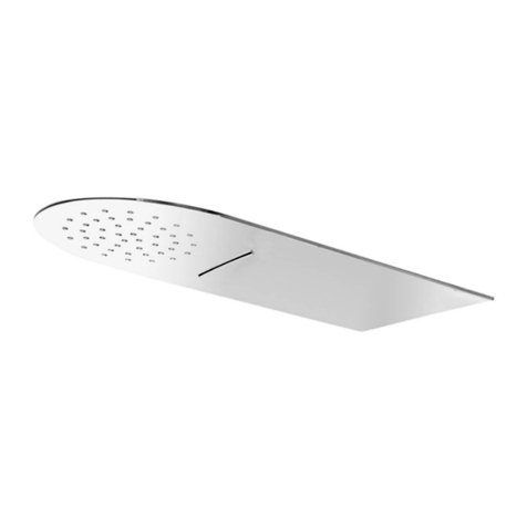
  9. RamonSoler RELNK500 99Z300715 User manual

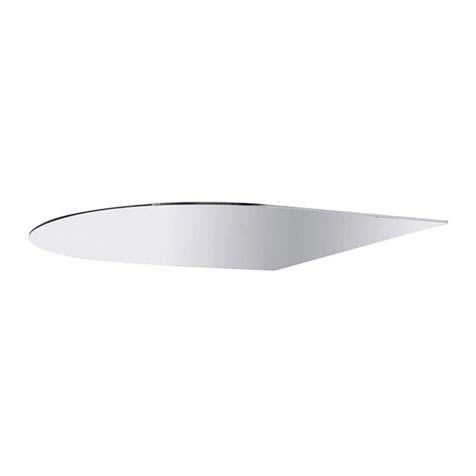
RamonSoler RELNK500 99Z300715 User manual

RELN550
RELNRK
RELNK500
2
Ref. RELN550 (Ø 550/H=50mm)
Ref. RELNK500 (X=500/H=50mm)
DIBUJO TÉCNICO/TECHNICAL DRAWING
DESSIN TECHNIQUE/TECHNISCHE ZEICHNUNG
1. Fischer SX 8 x 40 2. DIN 6923 M6
(x3) (x9) (x3)
3. DIN 975 M6 L=500mm
(x4) (x2)(x1) (x1)
6. Limiter 12l/min 7. Connection 1/2”M-1/2”M 8. Connection 1/2”M-1/2”F
4. Gloves
1. Fischer SX 8 x 40 2. DIN 6923 M6
(x4) (x12) (x4)
3. DIN 975 M6 L=500mm
(x4) (x2)(x1) (x1)
6. Limiter 12l/min 7. Connection 1/2”M-1/2”M 8. Connection 1/2”M-1/2”F
4. Gloves
Ø
H
H
X
X
5. Filter (x2 Recambio/Spare part)
3
Ref. RELNRK (X=400/Y=700/H=50mm)
1. Fischer SX 8 x 40 2. DIN 6923 M6
(x4) (x12) (x4)
3. DIN 975 M6 L=500mm
(x4) (x3)(x2)
6. Limiter 12l/min
Min. 1 Bar
Max. 5 Bar
Correct 2-3 Bar
Max. 70 ºC
Correct 38 º/40 ºC
7. Connection 1/2”M-1/2”F
Flow 3 Bar
RELN550 12 l/min
11,5 l/min (6 Nebuliz.)
RELNK500 13 l/min
8,5 l/min (4 Nebuliz.)
RELNRK 19,5 l/min
8,5 l/min (4 Nebuliz.)
220/240cm
175cm
ESPECIFICACIONES/SPECIFICATIONS
SPÉCIFICATION/SPEZIFIKATION
4. Gloves
H
Y
X
5. Filter (x1 Recambio/Spare part)
4
Fig.1
MONTAJE/MOUNTING
MONTAGE/MONTAGE
INTRODUCCIÓN/INTRODUCTION
INTRODUCTION/EINFÜHRUNG
ES
EN
FR
DE
(ES) Para una correcta instalación es necesario
tener en cuenta sobre que superficie vamos a
colocar el rociador. El sistema de agua (E) debe
estar centrado en el marco, y el borde inferior
alineado con la superficie visible del techo.
(EN) For correct installation, the surface on
which the sprinkler will be installed needs to
be considered. The water system (E) must
be centred in the frame, and the lower edge
must be lined up with the visible surface of the
ceiling.
(FR) En vue d’une installation conforme, il
convient de tenir compte du support sur lequel
sera placé le système d’extinction automatique.
Il est important de centrer le système d’eau (E)
dans le cadre et d’aligner le bord inférieur avec
la partie visible du plafond.
(DE) Für eine ordnungsgemäße Installation
ist die Oberfläche zu berücksichtigen, auf
welcher der Brausekopf befestigt wird. Das
Wassersystem (E) muss im Rahmen zentriert
und der untere Rand sollte mit der sichtbaren
Deckenfläche ausgerichtet sein.
(ES) Antes de instalar su nuevo rociador es esencial
que limpie la instalación para eliminar impurezas
que queden en el sistema y que puede causar
daños en el rociador.
Recomendamos la instalación de filtros en las
tuberías de alimentación.
Todas las piezas deben ser retiradas de su embalaje
e inspeccionadas antes de la instalación por si
hubieran sufrido cualquier daño en el transporte.
Si no se siguen las instrucciones de instalación y
conexionado el producto quedará fuera de garantía.
(EN) Before installing your new sprinkler, it is
essential to clean the installation to eliminate any
impurities left in the system that could damage it.
We recommend installing filters in the supply
pipes.
All the parts must be removed from their
packaging and inspected before installing, in case
any of them have been damaged during transport.
If the installation and connection instructions are
not followed, the product warranty will be void.
(FR) Avant d’installer votre nouveau système
d’extinction automatique , il est indispensable de
nettoyer l’installation afin d’éliminer tout corps
étranger qui pourrait se trouver à l’intérieur du
système et l’endommager.
Nous vous recommandons d’installer des filtres
dans les tuyauteries d’alimentation.
Retirez l’emballage de chaque pièce. Avant de
procéder à l’installation, vérifiez si des dommages
ont pu être occasionnés par un transport incorrect.
En cas de non-respect des présentes instructions
d’installation et de branchement, la garantie du
produit sera sans effet.
(DE) Vor der Installation des Brausekopfes
ist es notwendig, die Anlage zu reinigen, um
Verunreinigungen zu entfernen, die im System
verbleiben und die Brause beschädigen könnten.
Wir empfehlen die Anbringung von Filtern an den
Zuleitungen.
Sämtliche Teile aus der Verpackung entfernen und
vor der Installation auf etwaige Transportschäden
prüfen.
Bei Nichtbefolgung der Anweisungen für die
Installation und den Anschluss verfällt die Garantie
für das Produkt.
5
ES
EN
FR
DE
Fig.2.1
Fig.2.2
Fig.3.1
MONTAJE/MOUNTING
MONTAGE/MONTAGE
(ES) Para la instalación en techo de obra, fijar a
través de las aletas (A y B) o mediante tornillos
en las ranuras (C).
(EN) To install on a structural ceiling, fix using
the flanges (A and B) or with screws in the
slots. (C).
(FR) Pour une installation dans un plafond
classique, fixez-le au moyen de vis à oreilles (A
et B) ou de vis dans les rainures (C).
(DE) Für die Installation in der Decke entweder
mittels der Klappen (A und B) oder mithilfe
der Schrauben in den Nuten festmachen (C).
(ES) Posteriormente selle el espacio entre el
marco y el techo.
(ES) En el caso de la instalación en falso techo
utilizar el kit de fijación, compuesto de varillas
y sus accesorios (1, 2, 3).
(EN) Then seal the space between the frame
and the ceiling.
(EN) If installing on a false ceiling, use
the fixing kit, consisting of rods and their
accessories (1, 2, 3).
(FR)Scellez ensuite l’espace entre le cadre et
le plafond.
(FR)En cas d’installation dans un faux plafond,
utilisez le kit de fixation composé de tiges et de
leurs accessoires (1, 2, 3).
(DE)Anschließend den Abstand zwischen
Rahmen und Decke abdichten.
(DE)BeieinerInstallationinderZwischendecke
das Befestigungsset, bestehend aus Stäben
und Zubehör, verwenden (1, 2, 3).
max. 500mm
6
Fig.3.2 Fig.3.3
2
2
1
2
Fig.3.4
3
MONTAJE/MOUNTING
MONTAGE/MONTAGE
ES
EN
FR
DE
(ES)Hacerelrecorteenelfalsotechocorrespondiente
a las medidas del marco interior del rociador. Hacer
los taladros al techo de obra para colocar las varillas
(3). Utilizar los tacos adecuados según el tipo de
material del cual sea la superficie a taladrar.
Introducir el marco por el recorte realizado, este
quedará apoyado sobre el falso techo gracias a las
aletas.
(ES) Fijar el marco del rociador mediante el
kit de montaje compuesto por las varillas (3),
tuercas (2) y tacos (1), tal y como se observa
en las imágenes. Cortar las varillas si fuera
necesario. La Fig.3.3 corresponde a la zona
superior de la varilla que va fijada al techo y la
Fig.3.4 corresponde a la fijación del marco.
(EN) Cut out an area of the false ceiling
corresponding to the dimensions of the
interior frame of the sprinkler. Drill the holes
to fix the rods (3) to the ceiling. Use the
appropriate wall plugs depending on the
surface to be drilled.
Place the frame into the hole, where it will be
supported on the false ceiling by its flanges.
(EN) Fix the sprinkler frame using the assembly
kit consisting of rods (3), screws (2) and wall
plugs (1), as shown in the illustrations. Cut the
rods if necessary. Fig. 3.3 shows the upper part
of the rod that is fixed to the ceiling and Fig. 3.4
shows the fixing of the frame.
(FR) Découpez le faux plafond selon les
dimensions du cadre intérieur du système
d’extinction automatique. Percez-le afin de fixer
les tiges (3) au plafond. Utilisez les chevilles
de fixation adaptées en tenant compte du
matériau à percer.
Dans le trou ainsi effectué, insérez le cadre qui,
au moyen d’ailettes, restera maintenu au faux
plafond.
(FR) Grâce au kit de montage composé de tiges
(3), d’écrous (2) et de chevilles (1), fixez le cadre
du système d’extinction automatique comme
indiqué sur les images. Si cela est nécessaire,
coupez les tiges. La Fig. 3.3 correspond à la
zone supérieure de la tige devant être fixée
au plafond et la Fig. 3.4 indique la fixation du
cadre.
(DE) Die Zwischendecke entsprechend
den Abmessungen des Innenrahmens des
Brausekopfes ausschneiden. Löcher bohren, um
die Stäbe an der Decke (3) zu platzieren. Die Dübel
entsprechend der Art des Materials verwenden,
aus dem die zu bohrende Oberfläche besteht.
Den Rahmen durch das ausgeschnittene Loch
führen. Dank der Klappen hält die Vorrichtung in
der Zwischendecke.
(DE) Den Rahmen des Brausekopfes mithilfe
des Montagesets, bestehend aus Stäben
(3), Schraubenmuttern (2) und Dübeln (1),
entsprechend den Bildern befestigen. Wenn
nötig, Stäbe zuschneiden. Abb. 3.3 zeigt den
oberen Bereich des Stabes, der an der Decke
befestigt wird. Abb. 3.4 zeigt die Befestigung
des Rahmens.
7
ES
EN
FR
DE
Fig.4 Fig.5
MONTAJE/MOUNTING
MONTAGE/MONTAGE
Fig.6
7
6
5
(ES)En ambas opciones de instalación, antes de
realizar las conexiones hidráulicas, acoplar el
rociador empotrado con el marco mediante los
cables de seguridad (F) y purgar la instalación.
(ES) Completar la instalación del rociador
mediante la realización de las conexiones
hidráulicas, utilizarsi es necesariolas conexiones
extras (8) como alargador. Colocar el filtro (5)
y el limitador (6) entre las conexiones flexibles
(7) y el rociador Fig.5. Compruebe el sistema
hidráulico y a continuación fije el marco con los
tornillos en sus asientos Fig.6.
(EN) For both installation options, before
connecting to the water supply, connect the
recessed sprinkler with frame using the safety
cables (F) and purge the installation.
(EN) Complete the sprinkler installation by
connecting to the water supply. If necessary,
use the extra connections (8) as an extension.
Place the filter (5) and the limiter (6) between
the flexible connections (7) and the sprinkler
(Fig. 5). Test the water system and then fix the
frame with the screws in their seats (Fig. 6).
(FR) Pour chaque type d’installation, avant
d’effectuer les raccords hydrauliques,
assemblez le système d’extinction automatique
encastré dans le cadre grâce aux câbles de
sécurité (F) et purger l’installation.
(FR) Complétez l’installation du système
d’extinction automatique en réalisant les
raccordements hydrauliques. Si cela est
nécessaire, utilisez le raccord supplémentaire
(8) comme rallonge. Placez le filtre (5) et le
limiteur (6) entre le raccord flexible (7) et le
système d’extinction automatique (Fig. 5).
Vérifiez le système hydraulique et fixez ensuite le
cadre avec les vis dans leurs emplacements (Fig. 6).
(DE) Bei beiden Installationsmöglichkeiten
den eingebauten Brausekopf vor der
Verbindung der hydraulischen Anschlüsse
mithilfe der Sicherungskabel (F) mit dem
Rahmen verbinden und die Anlage säubern.
(DE) Die Installation des Brausekopfes durch
die Verbindung der hydraulischen Anschlüsse
abschließen.Dabei,fallsnotwendig,diezusätzliche
Verbindung (8) als Verlängerung verwenden. Den
Filter (5) und Durchflussbegrenzer (6) zwischen
dem flexiblen Anschluss (7) und dem Brausekopf
platzieren (Abb. 5). Das Hydrauliksystem
überprüfen und anschließend den Rahmen mit
den Schrauben an ihrem entsprechenden Platz
befestigen (Abb. 6).
PKIS0019

This manual suits for next models

2

Other RamonSoler Bathroom Fixture manuals

RamonSoler 8120B User manual

RamonSoler

RamonSoler 8120B User manual

RamonSoler RCEXT User manual

RamonSoler

RamonSoler RCEXT User manual

RamonSoler T20003 RP200 User manual

RamonSoler

RamonSoler T20003 RP200 User manual

RamonSoler RCRK 99Z300708 User manual

RamonSoler

RamonSoler RCRK 99Z300708 User manual

RamonSoler 745103 User manual

RamonSoler

RamonSoler 745103 User manual

RamonSoler 3333T User manual

RamonSoler

RamonSoler 3333T User manual

RamonSoler T100 D User manual

RamonSoler

RamonSoler T100 D User manual

RamonSoler RELED570 User manual

RamonSoler

RamonSoler RELED570 User manual

RamonSoler Soltronic 8102 User manual

RamonSoler

RamonSoler Soltronic 8102 User manual

Popular Bathroom Fixture manuals by other brands

Watermark PB-8524 quick start guide

Watermark

Watermark PB-8524 quick start guide

Akuaplus ELIAS SPB9629BL quick start guide

Akuaplus

Akuaplus ELIAS SPB9629BL quick start guide

agape NIVIS ACER0763FP0 Assembly instructions

agape

agape NIVIS ACER0763FP0 Assembly instructions

Axor 460/300 2jet 35275 Series manual

Axor

Axor 460/300 2jet 35275 Series manual

Croydex Luxury Round Shower Curtain Rod AD116541 manual

Croydex

Croydex Luxury Round Shower Curtain Rod AD116541 manual

Anzzi ANCHORAGE SP-AZ038 install guide

Anzzi

Anzzi ANCHORAGE SP-AZ038 install guide

Signature Hardware EXIRA THERMOSTATIC SHOWER installation guide

Signature Hardware

Signature Hardware EXIRA THERMOSTATIC SHOWER installation guide

bathstore OPTIM ALPHA 1100 quick start guide

bathstore

bathstore OPTIM ALPHA 1100 quick start guide

Zline EMBY-BTF-MB installation manual

Zline

Zline EMBY-BTF-MB installation manual

Glacier bay DORIND HD67110W-6001 Installation and care guide

Glacier bay

Glacier bay DORIND HD67110W-6001 Installation and care guide

Sanela Alex SLP 18RB Instructions for use

Sanela

Sanela Alex SLP 18RB Instructions for use

Kohler BEITOU 72830T-L installation instructions

Kohler

Kohler BEITOU 72830T-L installation instructions

Viega PureFlow Press Zero Lead Product instructions

Viega

Viega PureFlow Press Zero Lead Product instructions

HAFRO ICON TAPS 2 TASTI Assembly instructions

HAFRO

HAFRO ICON TAPS 2 TASTI Assembly instructions

unidrain ReFrame 7023 Mounting instructions

unidrain

unidrain ReFrame 7023 Mounting instructions

Toto WASHLET S500E SW3044 01 Series installation guide

Toto

Toto WASHLET S500E SW3044 01 Series installation guide

Toto TTLR201FK-1 instruction manual

Toto

Toto TTLR201FK-1 instruction manual

Luxart Serendipity SE341 Installation

Luxart

Luxart Serendipity SE341 Installation

manuals.online logo
manuals.online logoBrands
  • About & Mission
  • Contact us
  • Privacy Policy
  • Terms and Conditions

Copyright 2025 Manuals.Online. All Rights Reserved.