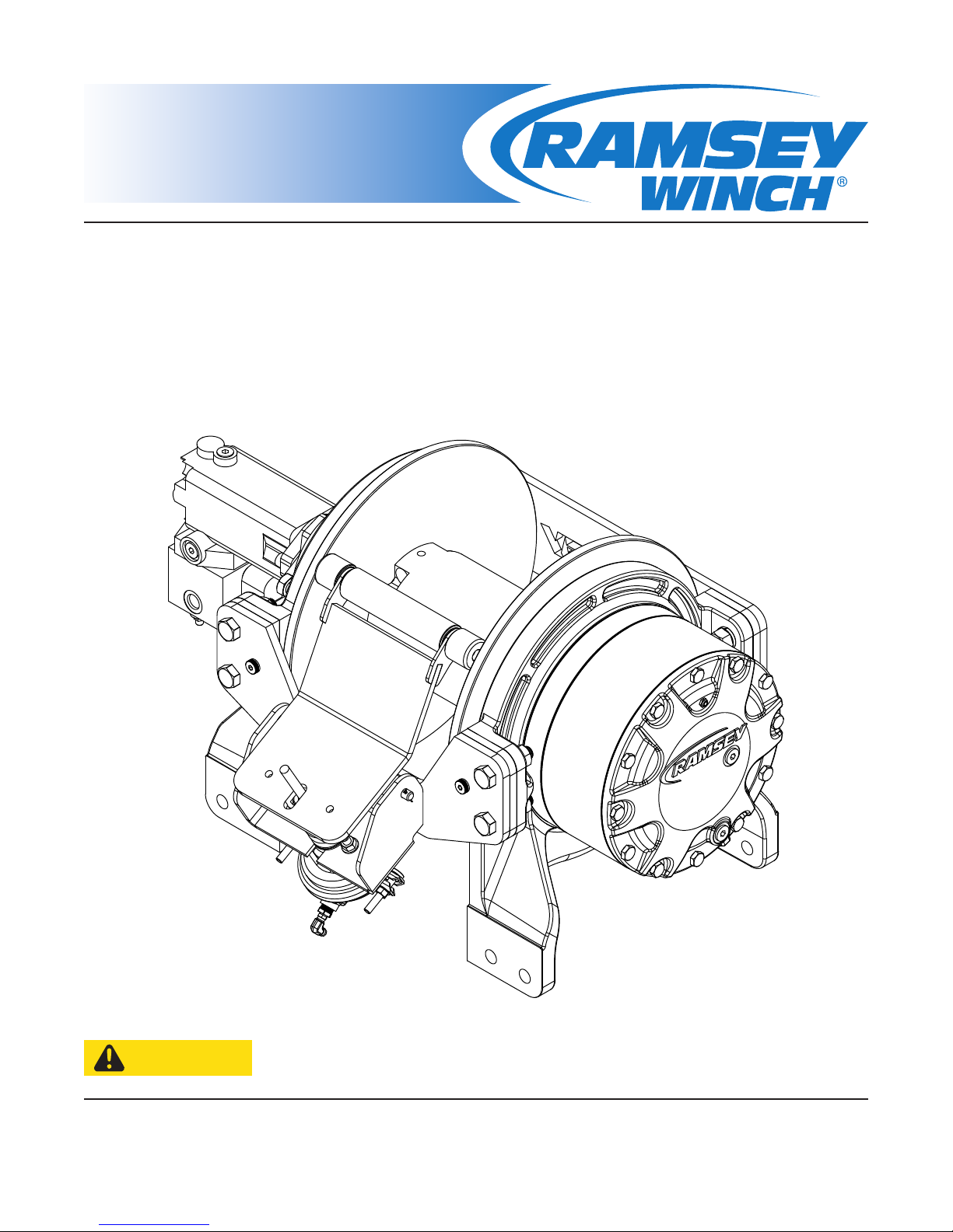
Ramsey Winch Hercules 50K User manual

Operating/Service/Maintenance Manual
Mailing Address:
P.O. Box 581510
Tulsa, OK 74158697
Phone: (918) 438-2760
Fax: (918) 438-6688
www.ramseyindustries.com
READ AND UNDERSTAND THIS MANUAL BEFORE INSTALLATION
AND OPERATION OF WINCH. SEE WARNINGS.
CAUTION
Hercules 50K
OM 914289-0918-B


1 Introduction ...................................................................................
2 Hydraulic System Requirements ........................................................
3 Winch Operation .............................................................................
Clutch Operation .....................................................................
Cable Installation ....................................................................
4 Synthetic Rope Installation ..............................................................
5 Rope Inspection Techniques .............................................................
6 Maintenance ..................................................................................
7 Instructions for Overhaul .................................................................
8 WinchMountingConguration..........................................................
R.H.HighAngleMountingConguration ....................................
L.H.HighAngleMountingConguration .....................................
R.H.StandardMountingConguration.......................................
L.H.StandardMountingConguration .......................................
9 R.H. High Angle Mount Dimensional View ...........................................
L.H. High Angle Mount Dimensional View ...........................................
10 R.H. Standard Mount Dimensional View .............................................
L.H. Standard Mount Dimensional View .............................................
11 Winch Exploded View ......................................................................
12 Drum Assembly ..............................................................................
13 Cable Tensioner ..............................................................................
SECTION PAGE
3
4
5
5
5
6
10
11
12
17
17
17
18
18
19
20
21
22
23
26
27
HERCULES 50K 1
Table of Contents

2HERCULES 50K

HERCULES 50K 3
Introduction 1
PLEASE READ THIS MANUAL CAREFULLY
ThismanualcontainsusefulideasinobtainingthemostefcientoperationfromyourRamsey
Winch, and safety procedures one needs to know before operating a Ramsey Winch. Do not operate
this winch until you have carefully read and understand the “WARNINGS” and “OPERATION”
sections of this manual.
WARRANTY INFORMATION
RamseyWinchesaredesignedandbuilttoexactingspecications.Greatcareandskillgointo
every winch we make. If the need should arise, warranty procedure is outlined on the back of your
self-addressedpostagepaidwarrantycard.Pleasereadandllouttheenclosedwarrantycard
and send it to Ramsey Winch Company. If you have any problems with our winch, please follow
instructions for prompt service on all warranty claims. Refer to back page for limited warranty.
WARNING
Clutch must be totally engaged before starting the winching operation.
Do not Start Winch motor before engaging clutch.
Do not disengage clutch under load.
Stay out from under and away from raised loads.
Stand clear of cable while pulling. Do not try to guide cable.
Do not exceed maximum line pull ratings shown in table.
Do not use winch to lift, support, or otherwise transport people.
A minimum of 5 wraps of cable around drum barrel is necessary to hold the load.
Cable anchor is not designed to hold load.
Use only Ramsey Winch recommended 3/4” synthetic rope.
A minimum of 8 wraps of Ramsey Winch recommended synthetic rope is necessary to hold load.
Cable anchor is not designed to hold load.
SPECIFICATIONS *(LOW SPEED)
RELATED LINE PULL (LBS.) .......................................................................................................................................... 50,000
(KGS.) ............................................................................................................................................ 2,670
GEAR REDUCTION ....................................................................................................................................................... 51.35:1
WEIGHT (WITHOUT CABLE) ................................................................................................................... 740 LBS. (336 KGS.)
LAYER OF CABLE 1 2 3 4 5 6
RATED LINE PULL
PER LAYER
LBS.
KGS.
50,000
22,680
41,800
18,960
36,000
16,320
31,600
14,330
28,100
12,740
25,400
11,500
CABLE
CAPACITY
FT.
M.
25
7
60
18
100
30
145
44
190
57
250
76
LINE SPEED
(AT 25GPM)
FPM
MPM
20
5.6
22
6.6
25
7.6
28
8.6
31
9.5
35
10.5
* THESE SPECIFICATIONS ARE BASED ON RECOMMENDED WIRE ROPE OF .75” DIAMETER EIPS CABLE AND 11.9
CU. IN./REV. MOTOR AT 2900 PSI WORKING PRESSURE.
* USE ONLY RAMSEY WINCH RECOMMENDED 3/4” SYNTHETIC ROPE.
* DIRECTIONAL CONTROL VALVE: 3-POSITION, 4 WAY MOTOR SPOOL.
* WINCH MEETS SAE J706.

4HERCULES 50K
B
TYPICAL LAYOUT
WITH BRAKE RELEASE SHUTTLE
MOTOR
BRAKE
PORT
A
SYSTEM
RELIEF
3 POSITION
4 WAY VALVE
(MOTOR SPOOL)
MAX. FLOW &
PRESSURE AT
RATED LOAD:
HIGH PRESSURE LINE
(.50 I.D. MINIMUM)
LOW PRESSURE LINE
(.75 I.D. MINIMUM)
PORT CONTROL
25 GPM
2900 PSI
PUMP
2 Hydraulic System Requirements
Refer to the performance charts to properly match your hydraulic system to Hercules 50K winch
performance.
(1)Linepull(lbs.)rstlayervs.workingpressure(PSI)and(2)linespeed(FPM)rstlayervs.ow
(GPM). Performance is based on a motor displacement of 11.9 cubic inches with 25 GPM maximum
owrate.Seepage10formotorportsize.

HERCULES 50K 5
Winch Operation 3
The best way to get acquainted with how your winch operates is to make test runs before you use
it. Plan your test in advance. Remember, you hear your winch, as well as see it operate. Learn to
recognizethesoundsofalightsteadypull,aheavypull,andsoundscausedbyloadjerkingor
shifting.Gaincondenceinoperatingyourwinchanditsusewillbecomesecondnaturewithyou.
The uneven spooling of cable, while pulling a load, is not a problem, unless there is a cable pileup
on one end of drum. If this happens, reverse the winch to relieve the load and move your anchor
pointfurthertothecenterofthevehicle.Afterthejobisdoneyoucanunspoolandrewindfora
neat lay of the cable.
CLUTCH OPERATION
To engage clutch:
1. Move the clutch control valve to the “clutch engaged” position.
2.Anytimethetemperatureisbelowfreezing,runthemotorinthe“cableout”directiononlyuntil
the drum starts to turn. In extreme cold temperatures (below 0° F/-18° C), pull out on the cable
by hand only until the drum starts to turn.
3. Wait at least 3 seconds for the clutch to fully engage, after which the winch is ready to winch in
the cable.
Donotattempttoengagetheclutchbyrstrunningthewinchmotorand
then moving the clutch control valve to the “clutch-engaged” position while
the motor is running. Do not start picking up the load at the same time the
clutch is being engaged.
To disengage clutch: Run the winch in the “cable out” direction until the load is off the cable.
4. Move the clutch control valve to the “clutch-disengaged” position.
5. The cable may now be pulled off by hand.
CABLE INSTALLATION
1. This winch has a cable anchor located at each end of the drum which
allows cable installation on either end.
2. Unwind cable by rolling it out along the ground to prevent kinking.
Securely wrap end of wire rope opposite hook, with plastic or similar
tape to prevent fraying.
3. Insert the end of cable, opposite hook end, into the hole in drum
barrel. Secure cable to drum barrel, using setscrew furnished with
winch. TIGHTEN SETSCREW SECURELY.
4. Carefully run the winch in the “reel-in” direction. Keeping tension on
end of cable, spool all the cable onto the cable drum, taking care to
form neatly wrapped layers.
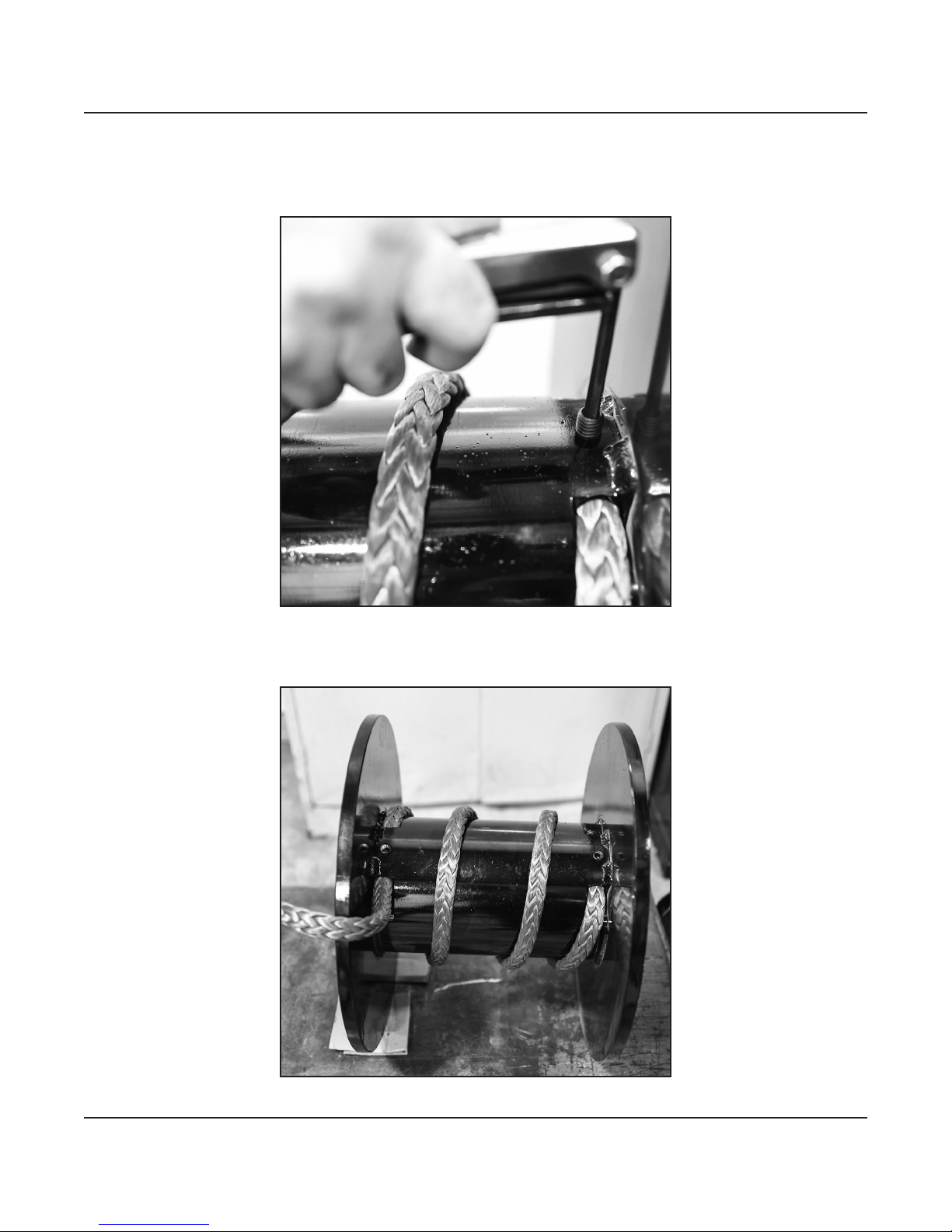
SYNTHETIC ROPE
The roller tensioner must be removed to use synthetic rope.
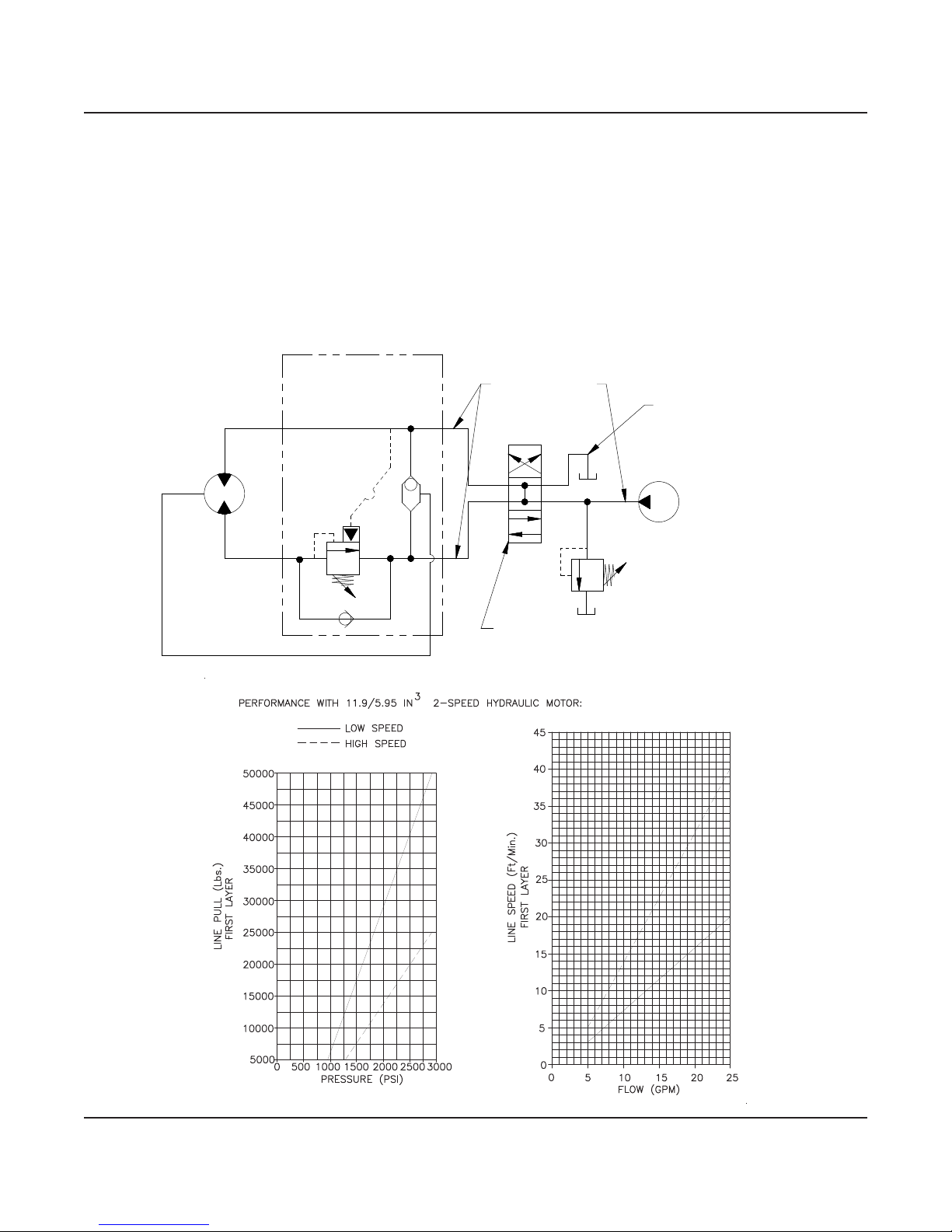
1.Useonly12strand(HMPE)highmoduluspolyurethanebercoatedsyntheticrope,commonly
known as Dyneema (MBS 58,000 lbs.). Maximum Winch capacity is 250 ft. of 3/4” rope.
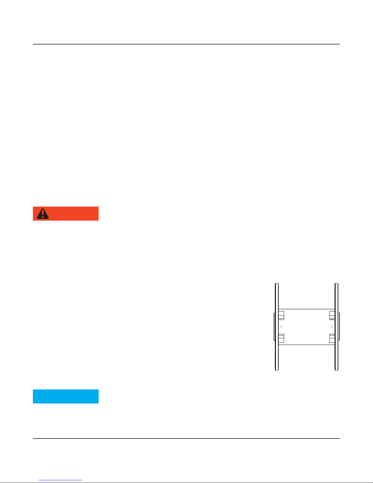
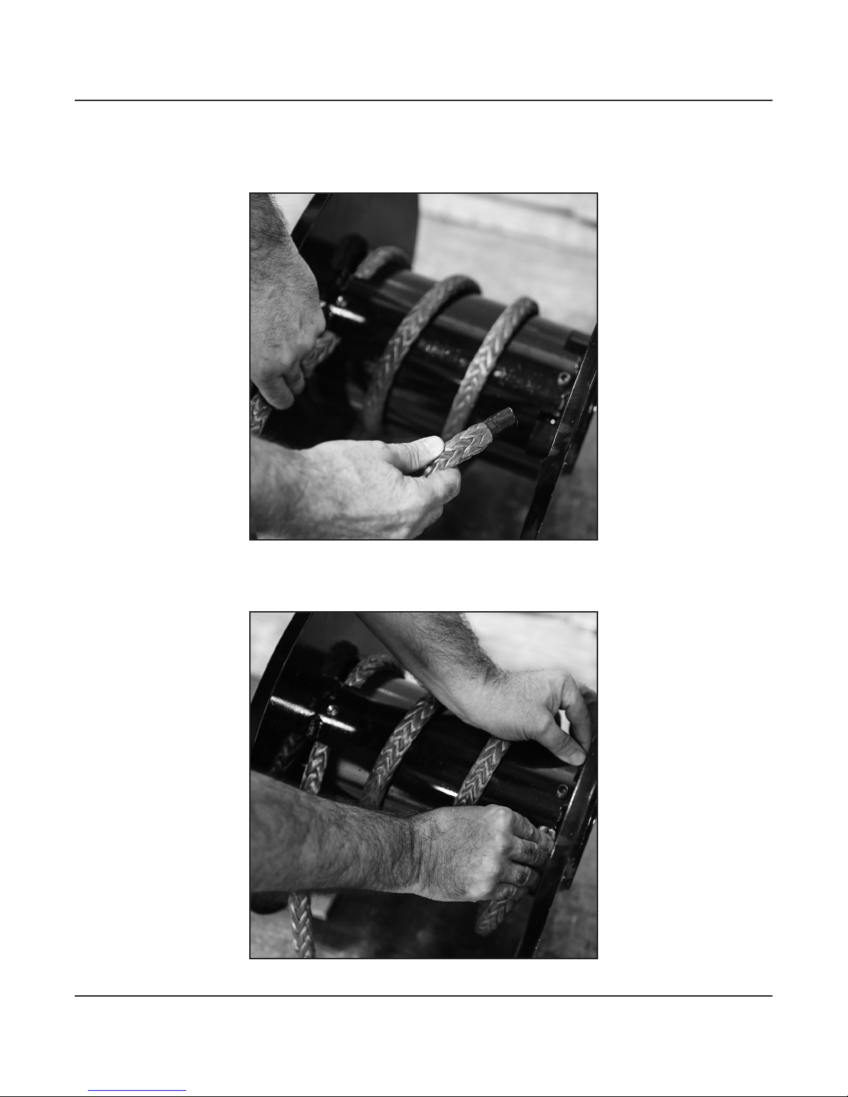
2. Install and anchor synthetic rope as shown below.
WARNING
NOTICE

6HERCULES 50K
4 Synthetic Rope Installation
1. Tape the end of the rope with electrical tape 2”-3” from end as shown in picture. This will aid in
installing the rope through the anchor hole.
2. Run rope through anchor hole. Pull approximately 60” of rope past anchor.

HERCULES 50K 7
Synthetic Rope Installation 4
3. Spiral wrap rope around drum barrel, approximately 3 times, evenly spaced to second anchor
hole.
4. Push rope into anchor hole until it is even with back side of hole.

8HERCULES 50K
4 Synthetic Rope Installation
5.Tightenanchorsetscrewuntilitisushwithdrumbarrel.
6. Pull excess slack from rope until rope is tight against drum barrel.

HERCULES 50K 9
Synthetic Rope Installation 4
7. Wind rope onto drum (no load) for minimum of 8 wraps before applying load to install entire
length of rope.

10 HERCULES 50K
5 Rope Inspection Techniques
INSPECTION WHAT CAUSE CORRECTIVE ACTION:
CUT STRANDS
REPAIR OR
RETIRE
•TWOORMORECUT
STRANDS IN PROXIMITY
•ABRASION
•SHARPEDGESAND
SURFACES
•CYCLICTENSIONWEAR
IF POSSIBLE, REMOVE AFFECTED
SECTION AND RESPLICE WITH A
STANDARD END-FOR-END SPLICE. IF
RESPLICING IS NOT POSSIBLE, RETIRE
THE ROPE.
COMPRESSION
NOT
PERMANENT
REPAIR
•VISIBLESHEEN
•STIFFNESSREDUCEDBY
FLEXING THE ROPE
•NOTTOBECONFUSED
WITH MELTING
•OFTENSEENONWINCH
DRUMS
•FIBERMOLDINGITSELF
TO THE CONTACT
SURFACE UNDER A
RADIAL LOAD.
FLEX THE ROPE TO REMOVE
COMPRESSION.
PULLED STRAND
NOT
PERMANENT
REPAIR
•STRANDPULLEDAWAY
FROM THE REST OF THE
ROPE
•ISNOTCUTOR
OTHERWISE DAMAGE
•SNAGGINGON
EQUIPMENT OR
SURFACES
WORK BACK INTO THE ROPE.
MELTED OR
GLAZED FIBER
REPAIR OR
RETIRE
•FUSEDFIBERS
•VISIBLYCHARREDAND
MELTED FIBERS, YARNS,
AND/OR STRANDS
•EXTREMESTIFFNESS
•UNCHANGEDBY
FLEXING
•EXPOSURETO
EXCESSIVE HEAT,
SHOCK LOAD, OR A
SUSTAINED HIGH LOAD
IF POSSIBLE, REMOVE AFFECTED
SECTION AND RESPLICE WITH A
STANDARD END-FOR-END SPLICE. IF
RESPLICING IS NOT POSSIBLE, RETIRE
THE ROPE.
DISCOLORATION/
DEGRADATION
REPAIR OR
RETIRE
•FUSEDFIBERS
•BRITTLEFIBERS
•STIFFNESS
•CHEMICAL
CONTAMINATION
IF POSSIBLE, REMOVE AFFECTED
SECTION AND RESPLICE WITH A
STANDARD END-FOR-END SPLICE. IF
RESPLICING IS NOT POSSIBLE, RETIRE
THE ROPE.
INCONSISTENT
DIAMETER
REPAIR OR
RETIRE
•FLATAREAS
•LUMPSANDBUMP
•SHOCKLOADING
•BROKENINTERNAL
STRAND
IF POSSIBLE, REMOVE AFFECTED
SECTION AND RESPLICE WITH A
STANDARD END-FOR-END SPLICE. IF
RESPLICING IS NOT POSSIBLE, RETIRE
THE ROPE.
ABRASION
REPAIR OR
RETIRE
•BROKENFILAMENTS
AND YARNS
•ABRASION
•SHARPEDGESAND
SURFACES
•CYCLICTENSIONWEAR
CONSULT ABRASION IMAGES* AND RATE
INTERNAL/EXTERNAL ABRASION LEVEL
OF ROPE. EVALUATE ROPE BASED ON
ITS MOST DAMAGED SECTION.
Minimal strength loss (continue use) Signicant strength loss (consult rope supplier) Severe strength loss (retire rope)

HERCULES 50K 11
Maintenance 6
Adhering to the following maintenance schedule will keep your winch in top condition and
performing as it should with a minimum of repair.
Weekly
1. Check the oil level and maintain it to the oil level plug. If oil is leaking out, determine location
and repair.
2. Check the pressure relief plug in the gear housing cover. Be sure that it is not plugged.
3. Lubricate cable with light oil.
Monthly
1. Check the winch mounting bolts. If any are missing, replace them and securely tighten any that
are loose. Use grade 5 or better bolts.
2. Inspect the cable. If the cable has become frayed with broken strands, replace immediately.
3. Inspect synthetic rope and follow inspection criteria.
Annually
1. Drain the oil from the winch annually or more often if winch is used frequently.
2. Fill the winch to the oil level plug with clean kerosene. Run the winch a few seconds with no load
in the reel in direction. Drain the kerosene from the winch.
3.Rellthewinchtotheoillevelplugwithall-purposeSAE75W-90syntheticgearoil.
4. Inspect frame and surrounding structure for cracks or deformation.
TROUBLESHOOTING GUIDE
CONDITIONS POSSIBLE CAUSE CORRECTION
OIL LEAKS FROM WINCH 1. SEALS DAMAGED OR WORN
2. TOO MUCH OIL
3. DAMAGED GASKETS
1. REPLACE SEAL
2. DRAIN EXCESS OIL. REFER TO OPERATION
3. REPLACE GASKETS
WINCH RUNS TOO SLOW 1. LOW FLOW RATE
2. HYDRAULIC MOTOR WORN OUT
1. CHECK FLOW RATE. REFER TO HYDRAULIC
SYSTEMS PERFORMANCE CHART PAGE 2.
2. REPLACE MOTOR
CABLE DRUM WILL NOT
FREE-SPOOL
1. CLUTCH NOT DISENGAGED 1. CHECK AIR PRESSURE TO CLUTCH
CYLINDER: 100PSI MINIMUM REQUIRED.
REFER TO PAGE 15 FOR PORT LOCATION.
BRAKE WILL NOT RELEASE 1. BRAKE LINE DISCONNECTED
OR BLOCKED
1. CHECK BRAKE FUNCTION

12 HERCULES 50K
Disassembly
1. Drain oil from gear housing cover by removing o-ring plugs #42. Remove tensioner assembly.
2.Disconnecthose#50fromelbow#43onvalve#51andtting#29onbrake#36.Remove
motor #39 and gasket #36a by removing (2) cap screws #20. Remove valve #51, if needed,
from motor by loosening (4) cap screws #14.
36a
39
51
14
20
43
50
42
7Instructions for Overhaul

HERCULES 50K 13
Instructions for Overhaul 7
3. Remove (12) cap screws #16 to remove gear housing cover and gasket from ring gear. Remove
input thrust washer, sun gear and input carrier assembly from inside ring gear. Remove ring gear
and gasket. Remove output carrier assembly. Replace if damaged or excessive wear.
4. Remove (8) cap screws #18 to remove clutch retainer plate #10 from clutch piston. Remove
clutch #9.
37
37
4
16
9
10
18

14 HERCULES 50K
5. Remove clutch housing #28 with piston #29 inside. To remove piston from clutch housing apply
air to 1/8” port. Remove o-rings #40 and #41 and inspect for damage or wear.
6. Remove (9) springs #49, thrust washer #25, gasket #37, output shaft #12 from gear end
bearing. Replace if damaged or excessive wear.
41
29
40
28
12
25
37
49
LONGEST
SPLINE
7Instructions for Overhaul

HERCULES 50K 15
Instructions for Overhaul 7
7. Remove winch tie bars #45, #44, and (4) spacers #46 by removing (8) cap screws #27, (8)
lock washers # 24, (8) nuts #23, and (4) shoulder bolts #26. Pull gear end bearing #6 from
drum assembly #1.
8. Pull drum assembly #1 from end bearing #7. Remove quad-rings #34 from grooves in drum
bushings. Remove input shaft #13 from end bearing. Examine splined ends of input shaft for
signs of wear, replace if damaged. Examine drum assembly #1 for signs of wear.
27 26
45
46
24 23
1
23
24
46
26 27
27
26
44
46
24
23
24
46
26
27
23
6
48
5
53
7
8
2
13
34 1
34

16 HERCULES 50K
9. If splines inside drum are damaged, drum must be replaced. If bushings show signs of wear,
replace by pressing old bushings from drum #101 and removing o-rings from grooves in drum.
Placewelloiledo-rings#106intodrum.Pressbushings#104intodrumuntilangeisushand
#103isushagainstdrum.
10. Remove brake assembly screws #15 attaching brake #36b to end bearing #7. Remove gasket
#36dfromendbearing.Takenoteofmountingcongurationforpropermountingofparts
during re-assembly.
103
105 101
105
104
15
36c
36b
36d
11
7
7 Instructions for Overhaul

HERCULES 50K 17
Winch Mounting Conguration 8
R.H. HIGH ANGLE MOUNTING CONFIGURATION
L.H. HIGH ANGLE MOUNTING CONFIGURATION

18 HERCULES 50K
8 Winch Mounting Conguration
R.H. STANDARD MOUNTING CONFIGURATION
L.H. STANDARD MOUNTING CONFIGURATION
Table of contents
Other Ramsey Winch Other manuals

Ramsey Winch
Ramsey Winch QUICK MOUNT 9000 User manual

Ramsey Winch
Ramsey Winch RE8000 User manual

Ramsey Winch
Ramsey Winch 400 Installation and user guide

Ramsey Winch
Ramsey Winch POWERMASTER SERIES 20,000 LB Installation and user guide

Ramsey Winch
Ramsey Winch Patriot Profile 9500 User manual

Ramsey Winch
Ramsey Winch SCH-8500 User manual

Ramsey Winch
Ramsey Winch UTV HONCHO 5000 User manual