3 OM-9560 & 9570 DROP-IN SERIES HEATED WELLS
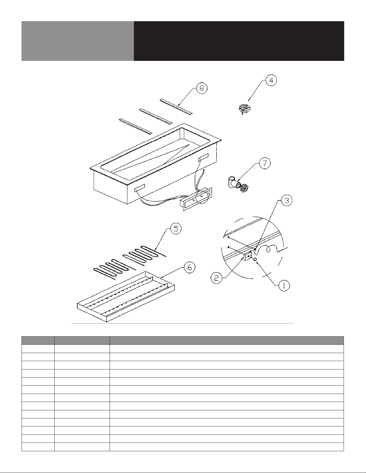
9570 INSTALLATION
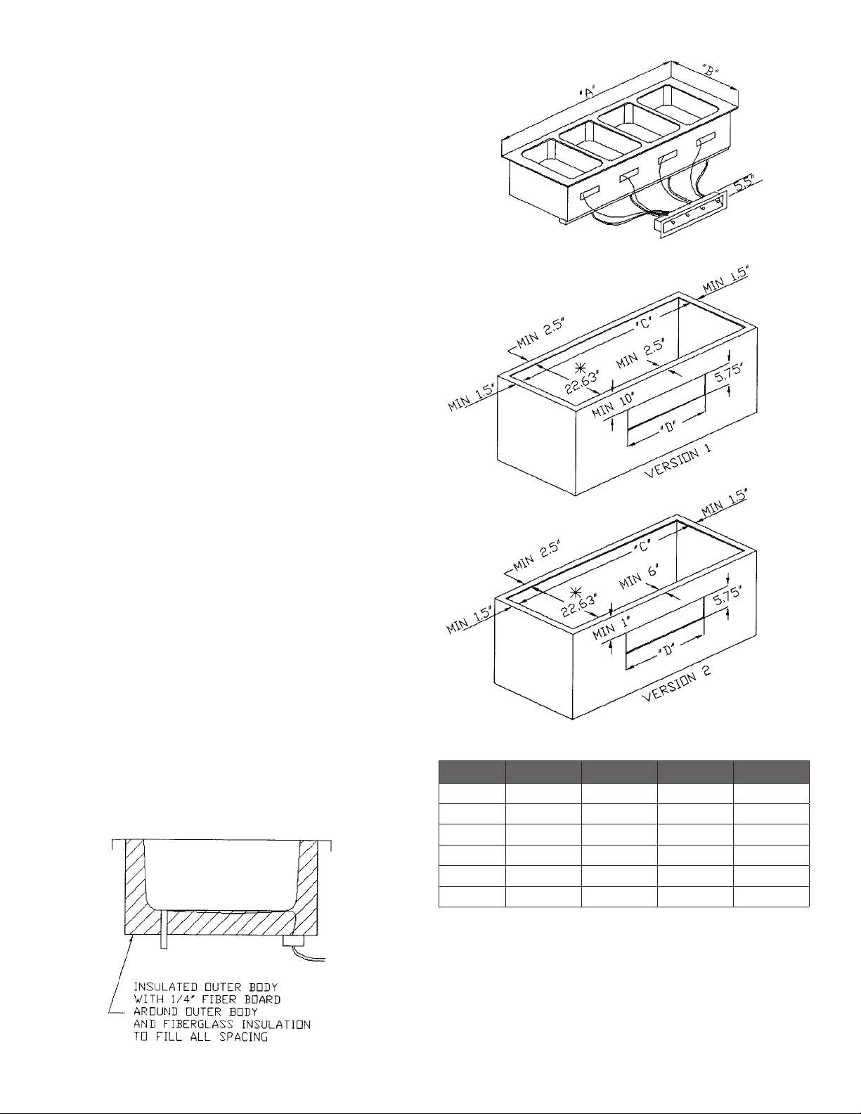
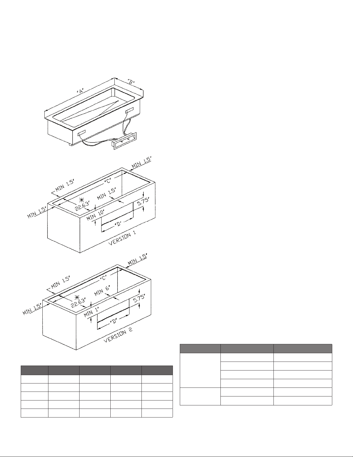
1. When installing Model 9570 Drop-in Hot Food unit, a clearance of 1.5”
on all sides and 6” clearance below the unit must be maintained from all
combustible materials.
2. Control panel must be inserted into front cutout before main unit is installed.
3. Secure unit to top and seal with NSF approved silicon.
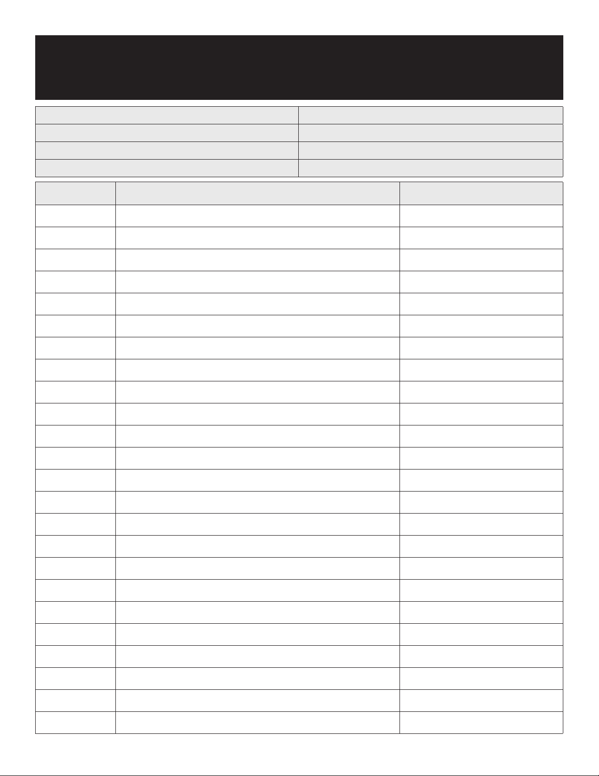
INSTALLATION REQUIREMENTS
MODEL “A” “B” “C” “D”
9570-2 31.25” 26” 28.25” 14”
9570-3 43.75” 26” 40.75” 14”
9570-4 56.5” 26” 53.375” 14”
9570-5 69.25” 26” 66.25” 14”
9570-6 82” 26” 78.9375” 14”
* REVISED CUTOUT SIZE FROM 22.5” TO 22.63” 10-18-95
OPERATION
All units are designed for 145° to 175° operation or 140° to 170° product
temperature. When using the unit dry expect at least a 15° drop in product
temperatures compared to using it wet. Electric hot food holding units may be
operated utilizing water or dry. Wet operation is usually recommended for higher
efficiency.
Plumbing: The units drain must have an outlet to an appropriate drainage area
or container.
Note: Drains must be plumbed to all applicable local code requirements.
Caution: Moisture collecting from improper drainage can create a slippery surface
on the floor and a hazard to employees. When making electrical connections refer
to the amperage data listed on the units data plate. Your local code or the national
electrical code handbook to be sure the unit is connected to the proper power source.
PREVENTATIVE MAINTENANCE
Randell strongly suggests a preventive maintenance program which would include
the following procedures:
1. Clean your hot food unit with a solution of warm water and a mild detergent.
The stainless steel portion of your unit can be polished with any quality
polish.
2. Drain water from wells daily and wipe them out. Clean wells thoroughly
twice a week to help insure a longer life for your wells.
Note: Do not use chemicals, steel wool or scrapers to clean unit.
Caution: Do not use abrasive cleaning solvents.
Proper maintenance of equipment is necessary to prevent costly repairs.
By evaluating each unit on a regular schedule you can often catch and repair
minor problems before they completely disable the unit. For more information
on preventive maintenance consult your local service company or www.CFESA.
com. Most repair companies offer this service at very reasonable rates to allow
you the time you need to run your business along with the peace of mind that
all your equipment will last throughout its expected life. These services often
offer guarantees as well as the flexibility in scheduling of maintenance for your
convenience. Randell believes strongly in the products it manufacturers and backs
those products with one of the best warranties in the industry. We believe with the
proper maintenance and use you will realize a profitable return on your investment
and years of satisfied service.
TROUBLESHOOTING
An electric hot food table operates on 120V, 208V or 240V circuits. It draws
power through either a fuse or circuit breaker panel; if you suspect an electri-
cal problem, check there first. The heating elements are controlled by electrical
temperature controls which sense and regulate temperature.
The following trouble shooting guide list the most common malfunctions in order
from most to least likely.
SYMPTOM POSSIBLE CAUSE PROCEDURE
Unit will not heat
Thermostat off Turn on
Unit unplugged Plug in unit
Circuit breaker tripped Replace breaker
Unknown problem Call preferred service agency
Individual well will
not heat
Thermostat off Turn on
Unknown problem Call preferred service agency
CONTACT US
If you have questions pertaining to the content in this manual, contact Randell
at 888-994-7636.