Randell PHHC-26 User manual

OPERATOR MANUAL
IMPORTANT INFORMATION, KEEP FOR OPERATOR
PART NUMBER PP MNL1001 (08/23)
This manual provides information for:
PHHC-26
HOT HOLDING CABINET
RETAIN THIS MANUAL FOR FUTURE REFERENCE
NOTICE: Due to a continuous program of product improvement, Randell reserves the
right to make changes in design and specifications without prior notice.
NOTICE: Please read the entire manual carefully before installation. If certain
recommended procedures are not followed, warranty claims will be denied.
MODELNUMBER_________________________
SERIAL NUMBER _________________________
INSTALLATION DATE ______________________
The serial number is located on the interior side wall
of the cabinet. An example is shown here.
EQUIPMENT DESCRIPTION
MODEL LENGTH DEPTH HEIGHT # PIZZA BOXES
(TWO FRONT TO BACK) VOLT AMPS NEMA SHIP WT (LBS)
PHHC-26 25” 33” 72” 36 115/1/60 9.7 5-15P
325
INSTALLATION
WARNING: FAILURE TO FOLLOW INSTALLATION GUIDELINES AND RECOMMENDATIONS
MAY VOID THE WARRANTY ON YOUR UNIT.
SELECTING A LOCATION FOR YOUR NEW UNIT
The following conditions should be considered when selecting a location for
your unit:
1. Floor Load: The area on which the unit will rest must be level, free of
vibration, and suitably strong enough to support the combined weights of
the unit plus the maximum product load weight.
2. Clearance: There must be a combined total of at least 6” clearance above
the top of the unit and also around each side of the top of the unit.
3. Ventilation: Avoid placing your unit in enclosed locations with low ceiling
height..
INSTALLATION CHECKLIST
WARNING: DAMAGE TO EQUIPMENT MAY RESULT IF NOT FOLLOWED. RANDELL IS NOT
RESPONSIBLE FOR DAMAGE TO EQUIPMENT IF IMPROPERLY INSTALLED.
NOTE: ALL MOTORS ARE OILED AND SEALED.
After the final location has been determined, refer to the following checklist prior
to start-up:
1. Check to ensure no damage has been sustained to the unit during shipment.
2. Check that fan motor and blade rotate freely without striking any stationary
members.
3. Unit must be properly leveled; check all legs or casters to ensure they all are
in contact with the floor while maintaining a level work surface. Adjusting
bullet feet heights or shimming casters may be necessary if the floor is not
level.
Information contained in this document is known to be current and accurate at the time of printing/creation. Reference our product line website for the most
updated product information and specifications. © 2023 Electrolux Professional, Inc. All Rights Reserved.
888-994-7636, fax 888-864-7636
unifiedbrands.net
THIS MANUAL MUST BE RETAINED FOR FUTURE REFERENCE. READ,
UNDERSTAND AND FOLLOW THE INSTRUCTIONS ANDWARNINGS CONTAINED
IN THIS MANUAL.
FOR YOUR SAFETY Do not store or use gasoline or other flammable vapors
and liquids in the vicinity of this or any other appliance.
NOTIFY CARRIER OF DAMAGE AT ONCE It is the responsibility of the
consignee to inspect the container upon receipt of same and to determine
the possibility of any damage, including concealed damage. Randell suggests
that if you are suspicious of damage to make a notation on the delivery
receipt. It will be the responsibility of the consignee to file a claim with the
carrier. We recommend that you do so at once.
Manufacture Service/Questions 888-994-7636.
Front View Back View

2 OM-PHHC-26 HOT HOLDING CABINET
4. Check all doors to ensure that they are sealing properly, are properly aligned,
and open and shut freely.
5. Confirm there is adequate supply voltage for the unit.
6. Plug in unit and turn on main on/off power switch.
7. Allow unit time heat to temperature. If temperature adjustments are required,
the temperature adjustment control is located on the face of the unit above
the door.
8. Refer to the front of this manual for serial number location. Please record this
information in your manual. It will be necessary when ordering replacement
parts or requesting warranty service.
9. Confirm that the unit is holding temperature. Set control to desired
temperature for your particular ambient and altitude.
10. Allow your unit to operate for approximately 2 hours before putting in
product to allow interior of unit to heat to storage temperature.
ELECTRICAL SUPPLY
The wiring should be done by a qualified electrician in accordance with local
electrical codes. A properly wired and grounded outlet will assure proper
operation. Please consult the data tag attached to the compressor to ascertain
the correct electrical requirements. Supply voltage and amperage requirements
are located on the serial number tag located inside the unit on the left interior
side wall.
CABINET DOORS
The doors on the PHHC-26 are reversible. The doors can be reversed by
removing the hinge screws located on the opposite side of the cabinet opening.
The smaller half size doors need to be rotated 180° and then secured into the
screw holes on the opposite side.
This same procedure can be followed for the full size door. In addition the hinges
that attach to the full size door will also need to be rotated 180° along with the
door latch. The cam lift hinge bushing within the cabinet mounted hinges will
need to be removed and inserted into the hinge to allow for proper pitch for door
closure.
SHELVES
Cabinet shelves are adjustable in 1” increments. To adjust shelving the shelf will
need to be removed. Remove all 4 clips for the shelf and set all 4 at the new
desired height making certain all 4 clips are at the same level. Re-install shelf
onto the clips.
OPERATION
WARNING: EVEN THOUGH YOUR REACH-IN WAS DESIGNED FOR HEAVY USE,
EXCESSIVE AND UNNECESSARY DOOR OPENINGS SHOULD BE AVOIDED IN
ORDER TO MAINTAIN PROPER BOX TEMPERATURE.
NOTE: THE HEATED CABINET IS DESIGNED AS A HOLDING CABINET AND WILL
MAINTAIN A TEMPERATURE RANGE OF 70° - 180°F. THE HEATED CABINET
IS NOT INTENDED TO COOK OR HEAT PRODUCT. PRODUCT ENTERING THE
CABINET SHOULD ENTER AT A MINIMUM OF 140°F.
Your heated holding unit will maintain proper temperatures when utilized properly.
It is strongly recommended that the doors be kept closed as much as possible.
Make sure the doors close properly after each use.
Your heated reach in unit was equipped with a temperature adjustment control
located on the top front of the unit. See Figure A. The temperature control has been
preset at the factory. Once the unit is powered on, allow 45 minutes to 1 hour for
the inside temperature to reach the factory set point of 160°F. Once the unit has
reached the set point it may then be loaded with product.
Figure A
TEMPERATURE CONTROL SETTINGS
PART NO. RANDELL CONTROL SETTINGS / PHHC-26 REF. NO DEF.
RF CNT1001 XR01CX-4N4LQ
Heated Upright Cabinet 1001
CODE LOCKED FACTORY SET
PARAMETER
Set Thermostat set point 160
HY Thermostat Differential (hysteresis) 5
LS Lower Set Point 150
US Upper Set Point 180
ot Offset Room Temp 0
od Output delay @ Startup 0
AC Anti-Cycle Time (min off after cycle) 0
CY Compressor ON time (probe failure) 0
Cn Compressor OFF (probe failure) 0
CH Kind of Action (Heating or Cooling) Ht
CF °C / °F F
rE Resolution 0.0°C (only °C) in
dy Display Delay 0
ALC Alarm Configuration Ab
AU Maximum Temperature Alarm 190
AL Minimum Temperature Alarm 140
iP Digital Input Plarity CL
iF Digital Input Configuration EA
di Digital Input Delay 5
dC Comp. and Fan Status when open door no
rd Regulation with door open n
PC Type of Probe ntc
rL Software Info 1.7
Pt Software info 12

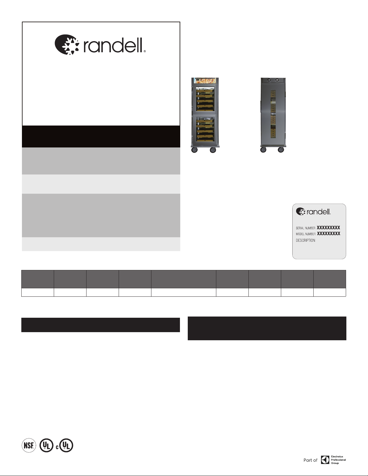
3 OM-PHHC-26 HOT HOLDING CABINET
ENTERING CONTROLLER PROGRAM MODE
1. Enter the Programming mode by pressing the “Set” and Arrow for 3
seconds. (the Fahrenheit symbol “F” will start blinking)
NOTE: If “of” appears the control is locked. Proceed to Unlocking the Keyboard
to unlock.
2. Enter full programming mode by again pressing the “Set” and Arrow for
8 seconds until L2 appears. Release the buttons and “HY” will appear with
a decimal point between the “H” and “Y” at the bottom. This indicates the
control is now in full programming mode.
3. While “HY” is on display push once and release.
4. “LS” will appear on display (this is the low set point)
5. Push and release “SET” once to view the current LS set point.
6. Continue this procedure of pushing “Set” and releasing to see the next code
on the sheet and the corresponding parameter for that code.
7. Should a parameter need to be changed you may use the or to get to
the desired new parameter.
8. Once the desired new parameter setting is achieved push and release “SET”
once. The new parameter will flash 3 times indicating the new parameter is
locked in.
9. After the parameter is locked in the control will then drop to the next code on
the chart. Continue by pushing the “Set” button to view the parameter of that
code.
10. Proceed until you have reached “HY” again.
11. Do not push any buttons for 8 seconds.
12. Once the temperature is displayed on the control you are now out of
programming mode,
13. You may now lock the keyboard if desired. Proceed to How to Lock the
Keyboard.
UNLOCKING THE KEYBOARD
1. Keep pressed together for more than 3 seconds the and keys until the
“on” message will be displayed.
LOCKING THE KEYBOARD
1. Keep pressed for more than 3 seconds the and keys.
2. The “of” message will be displayed and the keyboard will be locked. At this
point it will be possible only to see the set point or the MAX or Min temperature
stored.
3. If a key is pressed more than 3 seconds the “of” message will be displayed.
NOTE: Do not change parameters of control without consulting with Randell
Technical Support – 1.800.621.8560. Option 3.
PREVENTIVE MAINTENANCE
WARNING: DO NOT USE SHARP UTENSILS AND/OR OBJECTS.
WARNING: DO NOT USE STEEL PADS, WIRE BRUSHES, SCRAPERS, OR CHLORIDE
CLEANERS TO CLEAN YOUR STAINLESS STEEL.
CAUTION: DO NOT USE ABRASIVE CLEANING SOLVENTS, AND NEVER USE
HYDROCHLORIC ACID (MURIATIC ACID) ON STAINLESS STEEL.
Randell strongly suggests a preventive maintenance program which would include
the following procedures:
1. Clean all gaskets on a weekly basis with a solution of warm water and a mild
detergent to extend gasket life.
2. Wipe out any debris that has fallen into the cabinet on a daily basis.
3. Clean fan blades on a quarterly basis. It is recommended this be performed
by an authorized service agent.
Recommended cleaners for your stainless steel include the following:
JOB CLEANING AGENT COMMENTS
Routine cleaning Soap, ammonia,
detergent Medallion
Apply with a sponge or
cloth
Fingerprints and smears Arcal 20, Lac-O-Nu,
Ecoshine Provides a barrier film
Stubborn stains and
discoloration
Cameo, Talc, Zud,
First Impression
Rub in the direction of
the polish lines
Greasy and fatty acids, blood,
burnt-on foods
Easy-Off, Degrease It,
Oven Aid
Excellent removal on all
finishes
Grease and Oil Any good commercial
detergent
Apply with a sponge or
cloth
Restoration/Preservation Benefit, Super Sheen Good idea monthly
Reference: Nickel Development Institute, Diversey Lever, Savin, Ecolab, NAFEM
REPLACEMENT PARTS
To order parts, contact your Authorized Service Agent. Supply the model
designation, serial number, part description, part number, quantity, and when
applicable, voltage and phase.
CONTACT US
If you have questions pertaining to the content in this manual, contact Randell
at 888-994-7636.
TROUBLESHOOTING
This unit is designed to operate smoothly and efficiently if properly maintained.
However, the following is a list of checks to make in the event of a problem. Wir-
ing diagrams are found at the end of this manual. When in doubt, turn unit off
and contact service at 888-994-7636.
SYMPTOM POSSIBLE CAUSE PROCEDURE
Unit doesn’t heat
No power to unit Plug in unit
Temperature control turned
off Check temperature control
Temperature control faulty Test temperature control
High limit device Test high limit
Heating element faulty Test element
Control Error
Flashing HA Unit too hot / check probe
Flashing LA Unit too cool / check door
closure
Flashing P1 Check probe connection
Unit too hot
Temperature control too
high Adjust temperature control
Temperature control Test temperature control
Unit not hot enough
Door not sealing Inspect gasket & door hinges
Fan motor Raise temperature setting
Temperature control Adjust temperature control
Element Test elements

4 OM-PHHC-26 HOT HOLDING CABINET
Electrical Schematic
PHHC-26 Heated Holding Cabinet

5 OM-PHHC-26 HOT HOLDING CABINET
Parts List
PHHC-26 Heated Holding Cabinet

6 OM-PHHC-26 HOT HOLDING CABINET
Parts List
ITEM PART NUMBER DESCRIPTION
1 HD CST9802 CASTER, 3.5” SWIVEL W/ BRAKE
2 HD CST1009 CASTER, 3.5” RIGID
3 EL BLW1002 BLOWER ASSY, 115V
4 EL SWT610BE SWITCH, ILLUMINATED ROCKER
5 HD CLP150 S/S SHELF CLIP
6 HD HDL251 HANDLE, BLACK PLASTIC
7 HD HNG0706 DOOR HINGE, EDGEMOUNT, REAR DOORS
8 HD HIN0001 DOOR HINGE, KASON, FRONT DOOR
8A HD HIN0001-5 DOOR HINGE, CAM LIFT BUSHING (LARGE DOOR)
9 HD LCH1006 DOOR HANDLE/LATCH, FRONT DOOR
10 HD RCK1001 S/S RACK, 9.25” X 26.9” / FAN GUARD
11 HD SHL1004 S/S SHELF, 18” X 26.25”
12 IN GSK1012 GASKET, 21.77” X 59.84” SNAP IN
13 IN GSK1011 GASKET, 21.77” X 29.65” SNAP IN
14 EL ELM1100 ELEMENT, 120V, 1100W
15 EL WIR461-90 POWER CORD, 9’ 16/3 W/ 90°PLUG
16 RF FAN1002 FAN, AXIAL 115V/60HZ
17 RF FAN1003 WIRE FAN GUARD FOR RF FAN1002
18 RP CNT1100 CONTROL, DIXELL XR01CX W/ PROBE
19 RF CNT0505 PROBE, FOR DIXELL CONTROL
20 RP DOR1100 DOOR ASSY, FULL SIZE, OPERATOR SIDE
21 RP DOR1101 DOOR ASSY, 1/2 SIZE, CUST SIDE
22 RP PIL1100 PILASTER, ONE PIECE (NOT SET OF 4)
23 RP SHD1100 FAN SHROUD ENCLOSURE
24 RP DCT1100 VERTICAL AIR DUCT
PHHC-26 Heated Holding Cabinet

7 OM-PHHC-26 HOT HOLDING CABINET
Service Log
Model No: Purchased From:
Serial No: Location:
Date Purchased: Date Installed:
Purchase Order No: For Service Call:
Date Maintenance Performed Performed By
Table of contents
Other Randell Commercial Food Equipment manuals
Popular Commercial Food Equipment manuals by other brands

Tecnoinox
Tecnoinox B8FXGN9 Instruction manual for installation, maintenance and use

Jocel
Jocel JEXF-014559 instruction manual

ROCAM
ROCAM VEGA GN 1/1 C16 INSTRUCTION MANUAL, ASSEMBLY, INSTALLATION, USE AND MAINTENANCEE

Omcan
Omcan FW-CN-0905 instruction manual

Hendi
Hendi 201107 user manual

Inoksan
Inoksan PDE303 instruction manual