Rane HC6S User manual

Manual-1
HC 6S
HEADPHONE CONSOLE
OPERATORS MANUAL
QUICK START
Okay, you’re in a hurry. Well this section’s just for you. It explains enough of the HC 6S’s workings to keep you out of trouble. It al-
lows operation without reading the whole manual. Please read at least this section to ensure reasonable operation of the unit.
e HC 6S operates from either a common stereo or mono source, or from individual stereo sources. For a common stereo source,
plug the left and right input plugs into the respective MASTER INPUTS jacks. e Inputs accept balanced or unbalanced sources.
Just plug them in. is source is now routed to each of the six input channels to drive all of the Outputs.
For a single mono source feeding all headphones, connect it to one of the MASTER INPUT jacks and engage the STEREO/
MONO switch. Set the overall input level with the MASTER LEVEL, and use the channel LEVEL controls for individual head-
phones. ese Inputs may also be converted to balanced mono inputs by moving internal jumpers. See page Manual-4.
Use the separate stereo IN jacks when driving a pair of headphones with dierent program material than what is on the
MASTER INPUTS. Connecting a plug into these jacks automatically disconnects that channel from the Master Input program
material.
HC 6S CONNECTION
When rst connecting the HC 6S to other components, leave the
power o. is gives you a chance to make mistakes and correct
them without damage.
1. With the power switch in the o position, plug the power line
cord into the rear panel.
2. Plug the outputs from a mono or stereo source into the
MASTER INPUTS. For unbalanced systems use a standard
¼" TS cable. For balanced operation, use a stereo ¼" TRS
connector with pin 2 (+) wired to the Tip; pin 3 (–) wired
to the Ring; and pin 1 (ground) wired to the Sleeve. Please
consult the RaneNote, “Sound System Interconnection”
(enclosed) for additional wiring arrangements.
3. When rack mounting the HC 6S, you may wish to per-
manently wire the rear headphone Outputs to remote jack
locations, such as in walls of a studio or other rooms. Use the
front panel Outputs for local or control room monitoring.
4. You might also consider wiring the six direct stereo INs
permanently to a patch bay or monitor mixer, but only if you
do not plan to use the MASTER INPUTS as well. Whenever
a plug is inserted into any individual stereo IN, the MASTER
INPUTS are bypassed for that particular channel. So for
maximum exibility, we suggest that only the MASTER
INPUTs be permanently wired and that the direct stereo INs
be patched as necessary.
WEAR PARTS: is product contains no wear parts.
100
2
4
8
6
100
2
4
8
6
100
2
4
8
6
100
2
4
8
6
100
2
4
8
6
100
2
4
8
6
100
2
4
8
6
MONO
PHONES PHONES PHONES PHONES PHONES PHONESSIG
1
LEVEL LEVELSIG
2
LEVELSIG
3
LEVELSIG
5
LEVELSIG
6
LEVELSIG
4
STEREO LEVEL
MASTER
HC 6S
HEADPHONE
CONSOLE
POWER

Manual-2
FRONT PANEL DESCRIPTION
1 Front panel PHONES Output jacks are in parallel with the rear panel stereo OUT jacks. Use them to monitor any of the six
channels for level or mix adjustments, or for easy access when the HC 6S is rack mounted. Plugging into these front jacks does not
disengage the rear Outputs.
2 SIGnal present indicators light (green) with any input signal above -20 dBu. See OPERATING INSTRUCTIONS (on page
Manual-4) for complete details.
3 Individual LEVEL controls set the volume for each set of headphones, regardless of whether they are driven from the MASTER
INPUTS or from the direct stereo INs. When using the front and rear panel headphone jacks together, this control varies the level
of each headphone simultaneously.
4 MONO / STEREO switch converts the MASTER INPUTS from stereo to mono so that a single input cable drives both sides of
the headphones.
5 MASTER LEVEL sets the volume simultaneously to all headphones driven from the MASTER INPUTS. is does not alter the
volume on any headphones driven from the direct stereo INs.
6 POWER switch. Your basic, straightforward power switch. When the yellow LED is lit, the HC 6S is ready to go.
100
2
4
8
6
100
2
4
8
6
100
2
4
8
6
100
2
4
8
6
100
2
4
8
6
100
2
4
8
6
100
2
4
8
6
MONO
PHONES PHONES PHONES PHONES PHONES PHONESSIG
1
LEVEL LEVELSIG
2
LEVELSIG
3
LEVELSIG
5
LEVELSIG
6
LEVELSIG
4
STEREO LEVEL
MASTER
HC 6S
HEADPHONE
CONSOLE
POWER
1 2 3 4 5 6

Manual-3
REAR PANEL DESCRIPTION
Figure 1. Dual Mono to Stereo TRS Wye Cable.
See 2 above.
1 MASTER INPUTS are automatic balanced/unbalanced Inputs, which accept either a ¼" TRS (tip-ring-sleeve) plug for balanced
operation, or a ¼" TS (tip-sleeve) plug for mono operation. You do nothing dierent when hooking up balanced or unbalanced
lines. e HC 6S is one smart dude. He knows what you are doing so you better watch out.
2 Direct Stereo INs allow each stage to be driven separately, from any source. Whenever a plug is inserted into one of these Inputs,
the MASTER INPUTS are disconnected from that stage (and only that stage). I told you the dude be smart!
ese are ¼" TRS (tip-ring-sleeve) Input jacks, each accepting both left and right channels. If you plug a regular TS (tip-sleeve)
into this jack, you will only connect the left channel.
To feed this input with an unbalanced mono signal, use a TRS plug and wire the tip and ring together.
To build a cable that will combine separate left and right cables into a single ¼" TRS, follow the diagram below, connecting all
shields. RCA connectors can be substituted for the ¼" connectors.
To use balanced mono sources, set the internal jumpers as shown on page Manual-4.
3 Stereo Headphone OUTs allow any headphone with an impedance from 32 to 600 Ω. en kick back and enjoy. (Lower and
higher impedance headphones may be used; they just won’t be very loud.)
4 Universal Voltage Input: via a miniature IEC 60320 C6 appliance inlet. is mates with an IEC 60320 C5 line cord (USA
domestic). Do not lift the ground connection! e wide voltage range of this input allows it to be powered almost anywhere in the
world.
RIGHT
LEFT
RIGHT
SHIELD
T=LEFT
R=RING
S=SHIELD
LEFT
HC 6S
BALANCED
TIP = POSITIVE (+), RING = NEGATIVE (–),
SLEEVE = SHIELD UNBALANCED LINE INPUTS: TIP = LEFT, RING = RIGHT, SLEEVE = GROUND
RIGHT LEFT IN IN IN IN IN INOUT OUT OUT OUT OUT OUT
MASTER
INPUTS
654321
ACN 001 345 482
MADE IN U.S.A.
RANE CORP.
COMMERCIAL AUDIO
EQUIPMENT 24TJ
R
100-240 V
50/60 Hz 12 WATTS
This device complies with Part 15 of the FCC Rules. Operation is subject to the following two conditions: (1) this device may not cause
harmful interference, and (2) this device must accept any interference received, including interference that may cause undesire d operation.
2 34 1

Manual-4
OPERATING INSTRUCTIONS
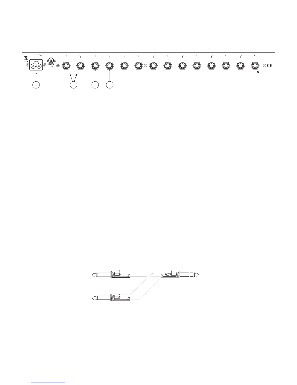
MASTER STEREO INPUTS
Apply a source program to the MASTER INPUTS and turn
up the MASTER LEVEL until the green signal-present LEDs
light up. Further adjustment of this control raises or lowers the
volume level in all headphones simultaneously, i.e., all those be-
ing driven from the MASTER INPUTS. e MASTER LEVEL
does not aect channels driven from the direct stereo INs.
INDIVIDUAL LEVEL CONTROLS
ese adjust the level in each set of headphones to the desired
loudness. When using a direct stereo IN, only this control aects
the volume in the headset—the MASTER LEVEL is bypassed.
DIRECT STEREO INPUTS
ese allow completely independent operation of up to six dier-
ent stereo programs. ese Inputs are stereo only, and wired to
accept unbalanced signals, using the tip=left, ring=right conven-
tion. Unbalanced mono sources require using a stereo ¼" TRS
plug and shorting the tip and ring together.
Any channel not directly driven is automatically driven from
the MASTER INPUTS.
When using balanced mono sources, internal jumpers must
be moved as in Figure 2 below. Jumpers are wired at the factory
for stereo. Jumpers must be moved for balanced mono operation.
Each jack is jumpered separate, so any combination of input
types is possible within a single HC 6S. SHOCK HAZARD
WARNING: Any service requiring access to the inside of the
unit (including changing jumpers and switch settings) should be
done by qualied service personnel.
©Rane Corporation 10802 47th Ave. W., Mukilteo WA 98275-5098 USA TEL 425-355-6000 FAX 425-347-7757 WEB www.rane.com
SIGNAL-PRESENT LEDS
ese light up with any signal input above -20 dBu. ey are
located in the signal path after the MASTER INPUTS and
before the individual LEVEL controls. is means that adjusting
the MASTER LEVEL aects the SIG LEDs, while adjusting the
individual LEVEL controls does not. When using a direct stereo
IN, the LED responds to that Input only. is means these
indicators aid in quickly identifying which stages are driven by
the MASTER INPUTS and which by the direct stereo INs:
Simply turn the MASTER LEVEL up and down and observe
which LEDs respond. ese are the channels being driven by the
MASTER INPUTS.
STEREO / MONO SWITCH
is serves the basic function of allowing both Left and Right
channels of all headphones to be driven from a mono MASTER
INPUT. In some instances a stereo program can be confusing
for live monitoring purposes, due to extreme separation and the
increased diculty in perceiving several dierent volume levels.
Using the MONO / STEREO switch converts the system to
mono operation to better suit these particular monitoring needs.
FRONT PANEL OUTPUT JACKS
ese jacks parallel the rear OUTs, providing easy access patch-
ing into any channel for cueing or additional monitoring. When
using more than six sets of headphones at once, keep two things
in mind:
1. ere are still only six LEVEL controls. Additional headsets
must double up with those already in use. To avoid intolerable
volume dierences to two listeners on the same channel of the
HC 6S, use headphones of the same make and model.
2. e HC 6S has limited power output. e more headphones
you connect to it, the less power there is available to each set,
and the more strain on the HC 6S. Blasting 10 or 12 sets
of low impedance headphones is asking too much from the
HC 6S. To lessen the power drain from the HC 6S, use only
high impedance (100 Ω or greater) headphones when paral-
leling.
Figure 2. Stereo Unbalanced / Mono Balanced Jumpers
Shipped as Stereo Unbalanced.
To channels 2 - 6
Other manuals for HC6S
2
Table of contents
Other Rane Dj Equipment manuals