Ranger Products R980X User manual

INSTALLATION AND OPERATION MANUAL
SHIPPING DAMAGE CLAIMS
When this equipment is shipped, title passes
to the purchaser upon receipt from the carrier.
Consequently, claims for the material damaged in
shipment must be made by the purchaser against
the transportation company at the time shipment is
received.
BE SAFE
Your new Ranger tire changer was designed and
built with safety in mind. However, your overall
safety can be increased by proper training and
thoughtful operation on the part of the operator.
DO NOT operate or repair this equipment
without reading this manual and the
important safety instructions shown inside.
1645 Lemonwood Dr.
Santa Paula, CA. 93060, USA
Toll Free: 1-800-253-2363
Tel: 1-805-933-9970
Fax: 1-805-933-9160
www.rangerproducts.com
PLEASE READ THE ENTIRE CONTENTS OF THIS MANUAL PRIOR TO
INSTALLATION AND OPERATION. BY PROCEEDING YOU AGREE THAT
YOU FULLY UNDERSTAND AND COMPREHEND THE FULL CONTENTS OF
THIS MANUAL. FORWARD THIS MANUAL TO ALL OPERATORS. FAILURE TO
OPERATE THIS EQUIPMENT AS DIRECTED MAY CAUSE INJURY OR DEATH.
REV D 04-20-11
PN# 5900157
MODELS:
R980X
R980X- AT
TIRE CHANGER
FOR SERVICING
AUTOMOBILE
AND LIGHT TRUCK
SINGLE PIECE
TIRES / WHEELS
Keep this operation manual near the
machine at all times. Make sure that
ALL USERS read this manual.
R980X-AT
R980X

This instruction manual has been prepared especially for you.
Your new tire changer is the result of over 25 years of continuous research, testing
and development and is the most technically advanced tire changer on the market today.
The manner in which you care for and maintain your tire changer will have a
direct effect on it’s overall performance and longevity.
READ THIS ENTIRE MANUAL
BEFORE OPERATION BEGINS.
RECORD HERE THE FOLLOWING INFORMATION
WHICH IS LOCATED ON THE SERIAL NUMBER DATA PLATE.
Serial No. __________
Model No. __________
Manufacturing date __________
Revision __________
R980X / R980X-AT
RimGuardTM Swing-Arm Tire Changer
2
PRODUCT WARRANTY
Your new tire changer is covered under warranty for one year on equipment structure; one year on all operating
components and tooling/accessories, to the original purchaser, to be free of defects in material and workmanship.
The manufacturer shall repair or replace at their option for this period those parts returned to the factory freight prepaid
which prove upon inspection to be defective. The manufacturer will pay labor costs for the first 12 months only on parts
returned as previously described.
The warranty does not extend to...
t defects caused by ordinary wear, abuse, misuse, shipping damage, improper installation, voltage or lack of
required maintenance;
t damages resulting from purchaser’s neglect or failure to operate products in accordance with instructions
provided in the owner’s manual(s) and/or other accompanying instructions supplied;
t normal wear items or service normally required to maintain the product in a safe operating condition;
t any component damaged in shipment;
t other items not listed but may be considered general wear parts;
t damage caused by rain, excessive humidity, corrosive environments or other contaminants.
THESE WARRANTIES DO NOT EXTEND TO ANY COSMETIC DEFECT NOT INTERFERING WITH EQUIPMENT
FUNCTIONALITY OR ANY INCIDENTAL, INDIRECT, OR CONSEQUENTIAL LOSS, DAMAGE, OR EXPENSE THAT
MAY RESULT FROM ANY DEFECT, FAILURE, OR MALFUNCTION OF A BENDPAK INC./ RANGER PRODUCT OR
THE BREACH OR DELAY IN PERFORMANCE OF THE WARRANTY.
WARRANTY IS NOT VALID UNLESS
WARRANTY CARD IS RETURNED.
NOTE:
Every effort has been taken to ensure complete and accurate instructions have been included in this manual, however, possible product
updates, revisions and or changes may have occurred since this printing. BendPak Ranger reserves the right to change specications
without incurring any obligation for equipment previously or subsequently sold. Not responsible for typographical errors.

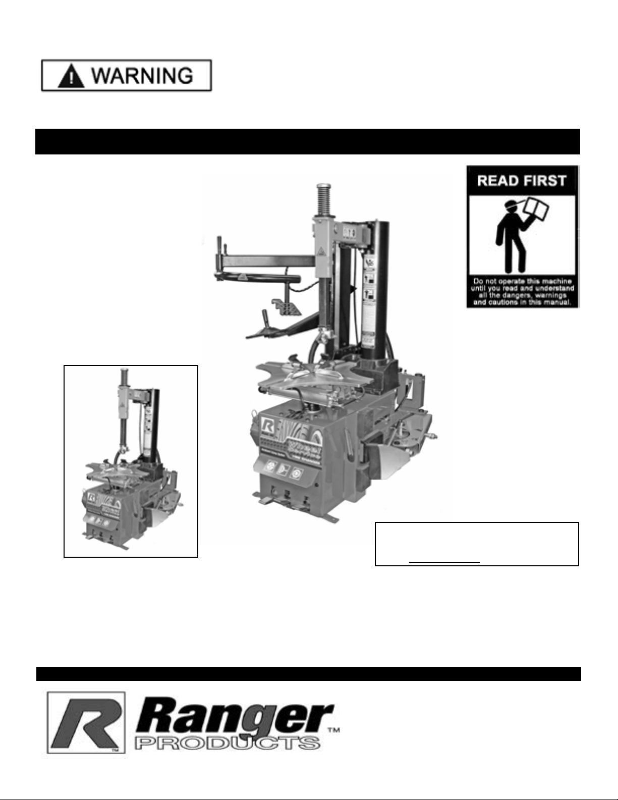
Failure to follow danger, warning, and caution instructions
may lead to serious personal injury or death to operator or
bystander or damage to property.
Do not operate this machine until you read and understand
all the dangers, warnings and cautions in this manual.
For additional copies
or further information, contact:
BendPak Inc. / Ranger Products
1645 Lemonwood Dr.,
Santa Paula, CA. 93060
1-805-933-9970
www.bendpak.com
www.rangerproducts.com
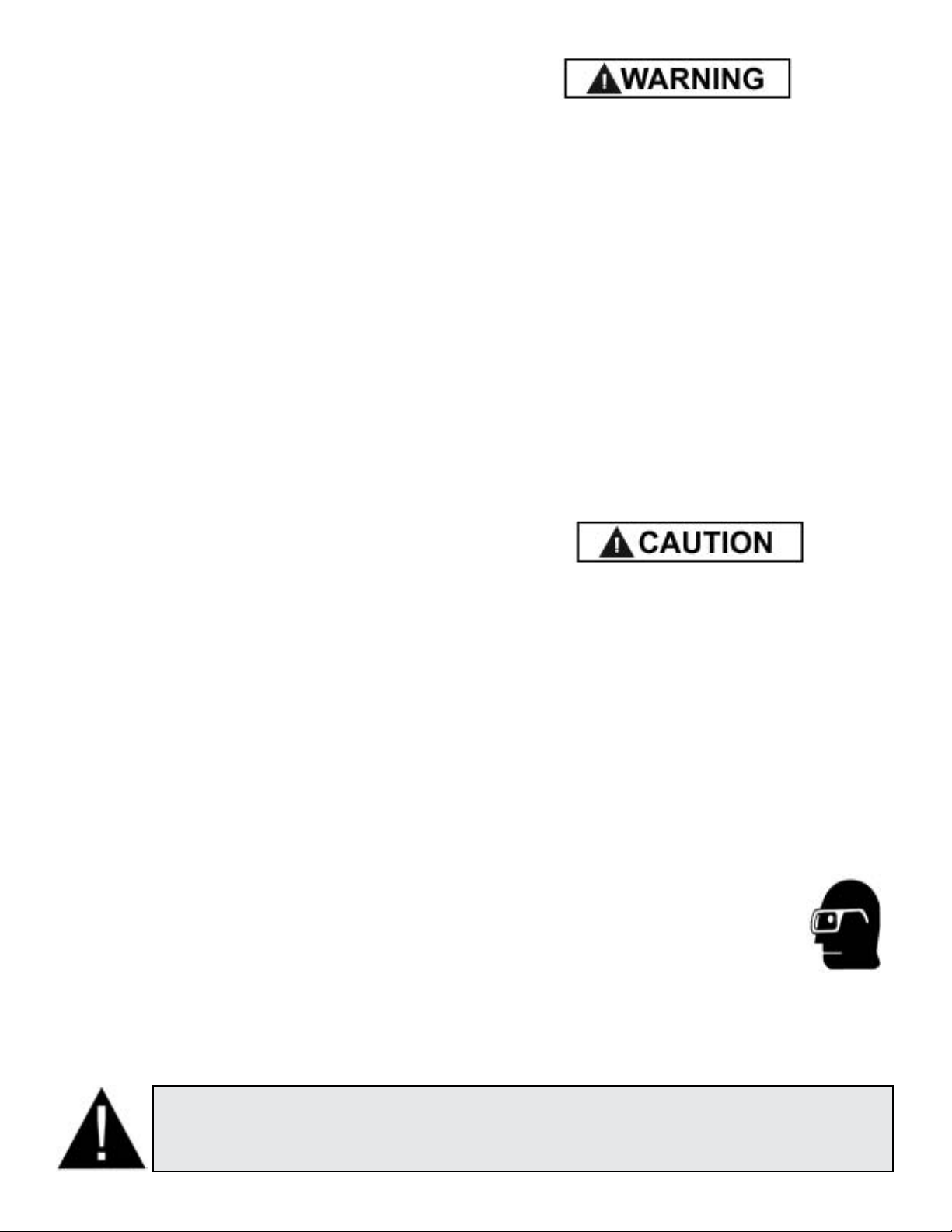
OPERATOR PROTECTIVE EQUIPMENT
Personal protective equipment helps make tire changing
safer. However, equipment does not take the place of safe
operating practices. Always wear durable work clothing
during tire service activity. Shop aprons or shop coats
may also be worn, however loose fitting clothing should
be avoided. Tight fitting leather gloves are recommended
to protect operators hands when handling worn tires and
wheels. Sturdy leather work shoes with steel toes and oil
resistant soles should be used by tire service personnel to
help prevent injury in typical shop activities.
Eye protection is essential during tire service activity.
Safety glasses with side shields, goggles,
or face shields are acceptable. Back belts
provide support during lifting activities
and are also helpful in providing operator
protection. Consideration should also be
given to the use of hearing protection if tire service activity
is performed in an enclosed area, or if noise levels are high.
3
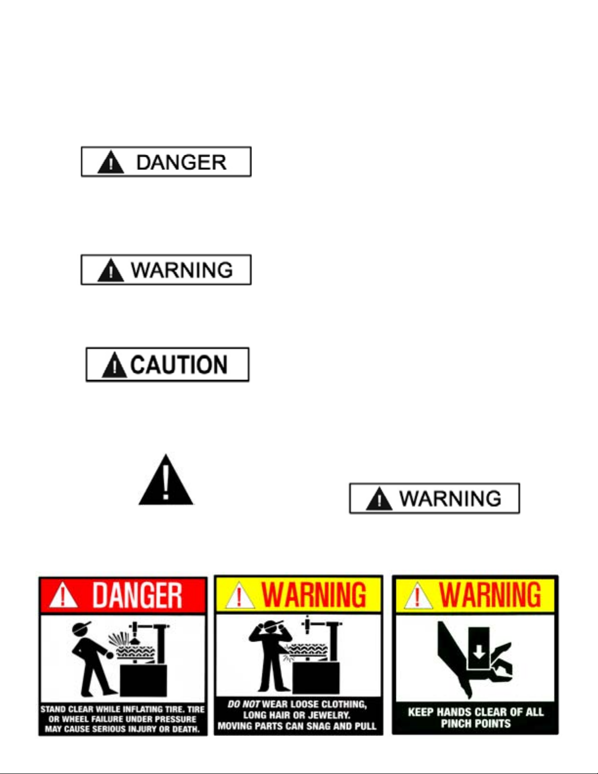
THIS SYMBOL POINTS OUT IMPORTANT SAFETY INSTRUCTIONS WHICH IF NOT FOLLOWED
COULD ENDANGER THE PERSONAL SAFETY AND/OR PROPERTY OF YOURSELF AND OTHERS
AND CAN CAUSE PERSONAL INJURY OR DEATH. READ AND FOLLOW ALL INSTRUCTIONS IN
THIS MANUAL BEFORE ATTEMPTING TO OPERATE THIS MACHINE.
TABLE OF CONTENTS
Page #
Warranty. . . . . . . . . . . . . . . . . . . . . . . . . . . . . . . . . . . . . 2
Operator Protection . . . . . . . . . . . . . . . . . . . . . . . . . . . . . 3
Section 1: Definitions of Hazard Levels . . . . . . . . . . . . . 4
Owner’s Responsibility . . . . . . . . . . . . . . . . . 4
Section 2: Safety Instructions . . . . . . . . . . . . . . . . . . . . . 5
Section 3: Tire and Wheel Service Safety Instructions . . 6
Section 4: Description of Parts . . . . . . . . . . . . . . . . . . . . 7
Section 5: Specifications / Tools Required . . . . . . . . . . . 8
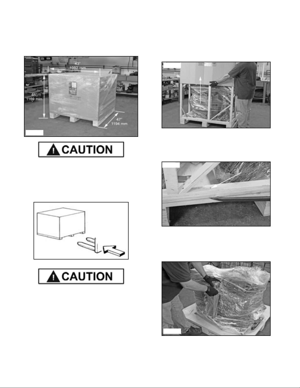
Section 6: Lifting / Uncrating Instructions . . . . . . . . . . 9-10
Section 7: Installation Location . . . . . . . . . . . . . . . . . . . 11
Section 8: R980X Assembly . . . . . . . . . . . . . . . . . . .12-15
Section 9: Anchoring /Air Source/ Oiler Adjustment . .15-16
Section 10: Electrical / Wiring Instructions . . . . . . . . . 16-17
Section 11: Operating Instruction . . . . . . . . . . . . . . . . . .18
Bead Loosening and Demounting . . . . . . . . .18
Important Wheel Mounting Instructions . . . . .19
Wheel Clamp Adjustments . . . . . . . . . . . . . 20
Section 12: Custom and Special Wheels . . . . . . . . . . . . 24
Demounting Tube Tires . . . . . . . . . . . . . . . . 24
Section 13: Mounting . . . . . . . . . . . . . . .. . . . . . . . . . . . 25
Section 14: Mounting Tube Type Tires . . . . . . . . . . . . . . 28
Section 15: Inflation / Inflation Pedal Operation. . . . . . . . 28
Section 16: Tire Inflation . . . . . . . . . .. . . . . . . . . . . . . . . 29
Stages Of Inflation . . . . . . . . . .. . . . . . . . . . 29
Stage One: Wheel Restraint R980X only . . . 30
Stage Two Bead Sealing . . . . . . . . . . . . . . . 30
Stage Three: Bead Seating . . . . . . . . . . . . 32
Stage Four: Inflation . . . . . . . . . . . . . . . . . . 33
Section 17: Maintenance Instructions . . . . . . . . . . . . . . 34
Air Dryer / Oiler . . . . . . . . . . . . . . . . . . . . . . 35
Inflation Pedal Pressure Limiter . . . . . . . . . . 36
Turntable Drive Belt . . . . . . . . . . . . . . . . . . . 37
Inflation Valve Lubrication . . . . . . . . . . . . . . 37
Transmission Oil Inspection / Lubrication . . 38
Critical Safety Warnings / Instructions . . . . . . . . . . . . . . 39
Service Parts . . . . . . . . . . . . . . . . . . . . . . . . . . . . . . 40-47
Wiring Diagram . . . . . . . . . . . . . . . . . . . . . . . . . . . . . . 48
Maintenance Notes /Tire and Wheel Data. . . . . . . . . . . . 49

SECTION 1
DEFINITIONS OF
HAZARD LEVELS
Identify the hazard levels used in this manual with the
following definitions and signal words:
DANGER
Watch for this symbol. It Means: Immediate hazards which
will result in severe personal injury or death.
WARNING
Watch for this symbol. It Means: Hazards or unsafe prac
tices
which could result in severe personal injury or death.
CAUTION
Watch for this symbol. It Means: Hazards or unsafe practices
which may result in minor personal injury or product or property
damage.
Watch for this symbol! It means BE ALERT!
Your safety, and/or the safety of others, is involved!
OWNER’S RESPONSIBILITY
To maintain machine and user safety, the responsibility of
the owner is to read and follow these instructions:
tFollow all installation instructions.
t Make sure installation conforms to all applicable Local,
State, and Federal Codes, Rules, and Regulations; such
as State and Federal OSHA Regulations and Electrical
Codes.
tCarefully check the unit for correct initial function.
t Read and follow the safety instructions. Keep them
readily available for machine operators.
t Make certain all operators are properly trained, know
how to safely and correctly operate the unit, and are
properly supervised.
t Allow unit operation only with all parts in place and
operating safely.
tCarefully inspect the unit on a regular basis and perform
all maintenance as required.
t Service and maintain the unit only with authorized or
approved replacement parts.
t Keep all instructions permanently with the unit and all
decal’s on the unit clean and visible.
Do not attempt to operate this equipment if you have
never been trained on basic tire service and mounting /
dismounting procedures.
4

5
SECTION 2
IMPORTANT SAFETY INSTRUCTIONS!
Read these safety instructions entirely!
1. READ AND UNDERSTAND all safety warning
procedures before operating lift.
2. KEEP HANDS AND FEET CLEAR. Remove hands
and feet from any moving parts.
3. KEEP WORK AREA CLEAN. Cluttered work areas
invite injuries.
4. Consider work area environment. Do not expose
equipment to rain . DO NOT use in damp or wet
locations. Keep area well lighted.
5. ONLY TRAINED OPERATORS should operate
this equipment. All non-trained personnel should be
kept away from work area. Never let non-trained
personnel come in contact with, or operate machine.
6. USE MACHINE CORRECTLY. Use machine in the
proper manner. Never use adapters other than what is
approved by the manufacturer.
7. DO NOT override or disable safety valves and/or
devices.
8. ALWAYS INSURE that all safety procedures are
followed before any attempt is made to work on or near
the equipment.
9. DRESS PROPERLY. Non-skid steel-toe footwear
is recommended when operating machine.
10. GUARD AGAINST ELECTRIC SHOCK. This
equipment must be grounded while in use to protect the
operator from electric shock. Never connect the green
power cord wire to a live terminal. This is for ground
only.
11. DANGER! The motor on this machine contains high
voltage. Disconnect power at the
receptacle before performing any
electrical repairs. Secure plug so that it
cannot be accidentally plugged in during
service.
12. WARNING! RISK OF EXPLOSION. This
equipment has internal arcing or sparking
parts which should not be exposed to
flammable vapors. This machine should
not be located in a recessed area or below
floor level.
13. MAINTAIN WITH CARE. Keep unit clean for
better and safe performance. Follow manual for proper
lubrication and maintenance instructions. Keep control
pedals and/or buttons dry, clean and free from grease
and oil.
14. STAY ALERT. Watch what you are doing. Use
common sense. Be aware.
15. CHECK FOR DAMAGED PARTS. Check for
condition of all moving parts, breakage of parts or any
condition that may affect the machines operation. Do
not use if any component is broken or damaged.
16. NEVER remove safety related components or
device from the machine. Do not use if safety related
components are damaged or missing.
17. To reduce fire hazard, keep engine/motor
exterior free of oil, solvent, or excessive
grease.
18. Illegible and missing warning labels must be
replaced immediately. Do not use the tire changer
if one or more labels are missing. Do not add any
object that could prevent the operator from seeing
the labels.

6
SECTION 3
TIRE AND WHEEL SERVICE
SAFETY INSTRUCTIONS
Only properly trained personnel should service tires and
wheels on the R980X/R980X-AT. Read all safety and
operating instructions thoroughly before use. The following
safety instructions are for one piece wheels only. Always
refer to the manufacturer’s procedures for multi-piece
wheels.
AlwAys wear durable personal protective work clothing
and safety gear during tire service activity. Refer to page
three for Operator Protective Equipment.
AlwAys remove all wheel weights and the valve core to
deflate the tire before servicing.
AlwAys keep all working surfaces clean and free of
debris.
AlwAys be aware of what each person is doing - and what
they will do before attempting any two-person operation.
AlwAys cover the electric motor and electrical
components before cleaning the tire changer. Be sure water
or cleaner does not enter the motor or electrical
components or come in contact with electrical connections.
AlwAys disconnect the electric power and air supply
before attempting any maintenance.
Demounting & Mounting
AlwAys clean and inspect the wheel prior to any service.
NEVER stand on the sliding carriage, frame or work table
while demounting or mounting a tire.
AlwAys keep hands, feet, and other objects away from
moving parts while the machine is turned on.
AlwAys place the narrow bead seat to the outside when
clamping. Failure to demount the tire from the narrow bead
seat side may cause damage to the tire beads.
AlwAys apply an approved rubber lubricant to rim flanges
and both tire beads before demounting or mounting and
seating the beads.
NEVER mount a tire on a damaged or rusty wheel as tire
or wheel failure may result during inflation. Explosion from
failure may result in severe injury or death of the operator
and bystanders.
Inflation
AlwAys be sure the bead opposite the tool is in the drop
center before rotating the tire when demounting or mounting
to avoid damage to the tire beads.
AlwAys follow all applicable Local, State, and Federal
Codes, Rules, and Regulations; such as the Federal OSHA
Standard Number 1910.177.
AlwAys use an approved inflation chamber or inflation
cage equipped with a self-gripping chuck and remote
inflation gauge and valve.
AlwAys inflate the tire to manufacturer’s recommended
cold operating pressure.
DO NOT OVER INFlATE! Tire or wheel failure during and
after inflation may result in an explosion capable of causing
severe injury or death.
NEVER reinflate a tire that has been run under inflated or
flat without first demounting the tire and checking for wheel
and tire damage.
AlwAys inspect the tire interior for loose or broken cords,
cuts, penetrating objects, and other damage. Discard tires
that cannot be properly repaired.
NEVER rework, weld, heat or braze wheels.
NEVER strike the tire or wheel with a hammer.
AlwAys be sure the tire diameter exactly matches the
wheel diameter.
Tire failure under pressure can be hazardous. When
possible, always place wheels inside an approved inflation
chamber or cage before inflating. Use an approved remote
inflation valve, hose, and gauge. ALWAYS wear safety
goggles for eye protection. Do not stand beside the wheel
or cage during inflation. Keep hands and other parts of the
body out of the cage during inflation. Observe the tire
pressure frequently. Do not exceed the manufacturer’s
recommended maximum inflation pressure. Failure to
follow these instructions may cause the tire and rim to
separate with tremendous force, resulting in serious
personal injury or death.

7
SECTION 4
DESCRIPTION OF PARTS
Fig. 4.1
Fig. 4.2
Fig. 4.4 Fig. 4.5
Fig. 4.3
1. Tank Pressure Relief Valve
2. Tower (Air Tank)
3. Tool Tray
4. Air Drier / Oiler / Pressure Gauge (See Fig. 4.2)
5. Bead Breaker Arm
6. Bead Breaker Blade
7. Bead Breaker Pad
8. Bead Lifting Tool
9. Turntable Foot Pedal (See Fig. 4.3)
10. Bead Breaker Foot Pedal (See Fig. 4.3)
11. Wheel Clamp Foot Pedal (See Fig. 4.3)
12. Lube Bottle / Brush
13. Turntable
14. Wheel Clamps
15. Mount /Demount Head
16. Turbo Blast Hose Assembly
17. Helper Disc
18 Drop Center Tool
19. Assist Tower Controls
20. Assist Arm
21. Vertical Shaft
22. Vertical Arm Assembly
23. Vertical Shaft Lock Handle
24. Vertical Shaft Spring
25. Voltage Selector Switch
(Located on Rear of Cabinet. (See Fig. 4.4)
26. Inflation Pedal
(Located on Left of Cabinet. See Fig. 4 .5)
R980X-AT

8
FEATURES / SPECIFICATIONS MODEL R980X /R-980X-AT
Type of Drive System Air / Electric
Motor Dual Voltage 110/220V 50/60HZ 1 Ph.
Air Requirement 140-165 PSI (10-11 BAR)
Wheel Clamping Method 4 Rim-Guard Clamps - Internal / External
Table Clamping System Dual Pneumatic Cylinders
Bead Breaking System Pneumatic Blade / Dual Settings
Turntable Speed -360-Degree Rotation 6.9 Seconds
Tool Holder Manual Lock
Adjustable Turntable Clamps Standard
Ination System Standard
Ination Pressure Regulator/Limiter Standard
Water Filter Standard
Oiler / Lubricator Standard
Air Regulators (Inator, Jaw Clamps, Assist Tower) Standard
Bead Lifting Tool Standard
Large Soap / Lubricator Bucket Standard
Brush Standard
Tower Design Rigid Fixed
Powerful "Turbo -Blast" Bead Seating System Standard
Tire Ination Standard
Tool Tray / Bin Storage Standard
Internal Wheel clamping Capacity * 11" – 24" (279 mm – 610 mm)
External Wheel clamping Capacity * 10" – 23" (254 mm – 584 mm)
Turntable Tire Width Capacity (Mounting) 4.5" – 17.5" (114 mm – 444 mm)
Bead Breaker Tire Width Capacity (Demounting) 1" – 14" (25 mm – 356 mm)
Maximum Tire Diameter 48" (1219 mm)
Shipping Weight R980X:620 lbs. (282 Kg)/ R980X-AT 680 lbs. (309Kg)
Specications are subject to change without notice.
* NOTE: Internal and External Wheel clamping dimensions do not translate directly to rim or tire sizes as Wheel
clamping points may vary by manufacturer.
SECTION 5
FEATURES / SPECIFICATIONS: MODEL R980X / 980X-AT
1. Pallet jack or forklift for moving crate
2. Forklift or Shop crane
3 Utility knife
4. Crow bar or pry bar.
5. Tin Snips or Sheet Metal Snips
6. Hammer
7. Open end metric wrenches and/or socket set
8. Phillips and Slot head screw drivers
9. Metric Allen Key set
Parts required but not supplied.
1. Teon tape
2. Air tting to match shop Air Supply line
3. Tool Oil
4. Anchor Bolts and Shims (if Anchoring)
TOOLS REQUIRED FOR ASSEMBLY and INSTALLATION

9
SECTION 6
LIFTING/ UNCRATING
1. The R-980X /AT is shipped on a pallet, Approximate
shipping dimensions. (See Fig 6.1)
CAUTION!
Handling of the machine must be performed only with
an appropriate lifting device such as a forklift or pallet
jack. Only personnel who are experienced and
qualified on material handling procedures should
handle any transportation or moving of machine.
CAUTION!
Be careful when cutting steel banding material as items
may become loose and fall causing personal harm or
injury. Always wear gloves when uncrating the machine to
prevent scratches, abrasions, or cuts due to the contact
with packing materials. Eye protection is essential during
uncrating service activity. Safety glasses with side shields,
goggles, or face shields are acceptable.
Remember to report any shipping damage to the carrier
and make a notation on the delivery receipt.
Uncrating Instructions
1. Carefully cut the plastic wrapping and remove.
2. Carefully cut open the top of the cardboard box. Either
lift off box or cut side panel and remove.
(See Fig 6.3)
3. Using a crow bar or pry bar, locate the staple/nail
locations and pry apart the wooden crating. Note: the entire
wooden frame can be lifted off after prying the staples /nails
at the base of the crate. (See Fig 6.4)
4. Carefully cut the Tire Changer free of the plastic
wrapping securing it to the Tire Changer base. Do not
unwrap the Assist Tower and Tower Tank at this time. The
wrapping helps keep the Swing arms from moving during
lifting and assembly. (See Fig 6.5 & 6.6)
Fig. 6.1
Fig. 6.2
Fig. 6.3
Fig. 6.4
Fig. 6.5

10
CAUTION!
Handling of the machine must be performed only
with an appropriate lifting device such as a forklift or
shop crane. Only personnel who are experienced and
qualified on material handling procedures should
handle any transportation or moving of machine.
CAUTION!
Secure the Air Tank / Assist Tower with shop crane/
forklift or personnel prior to cutting metal strapping
as Air Tank / Assist Tower may have shifted
during shipping. Be careful as banding may snap or
fly when tension is released.
CAUTION!
DO NOT set the Tank/Tower on its base. Protect the
fittings on the Tower base when lifting. Protect the
air hose coming out of the base of the Assist tower
and the fittings on the back side of the Assist Tower.
5. Either cut or unscrew the metal strapping holding the
Air Tower / Tank and Assist Tower to the pallet. Using a
fork lift or shop crane, remove both towers from the pallet
and set aside. Secure both towers so they can not fall.
(See Fig 6.7)
6. Remove the four front and rear Bolts and Nuts holding
the tire changer from the pallet. (See Figs. 6.8 - 6.9)
CAUTION!
Handling of the machine must be performed only
with an appropriate lifting device such as a forklift or
shop crane. Only personnel who are experienced and
qualified on material handling procedures should
handle any transportation or moving of machine.
7. Using a shop crane or fork lift with lifting straps,
remove the Tire Changer from the wooden pallet. Use
only properly rated lifting straps under the Tire Changer
base. (See Fig. 6.10)
8. Locate the tire changer using the guidelines in
Section 7, page 11.
Fig. 6.9
Fig. 6.10
Fig. 6.8
Fig. 6.7
Fig. 6.6

SECTION 7
INSTALLATION LOCATION
Disconnect tag and lock out power source before
attempting to install, service, relocate or perform any
maintenance.
Do not lift or move unit without appropriately rated
equipment. Be sure the unit is securely attached to any
lifting device used.
Never use the wood shipping skid for mounting the unit.
Select a location using Figures 7.1 and 7.2. The area
should provide the operator with enough space to use the
equipment in a safe manner. The area selected should be
well lit, easy to clean and should be away from oil, grease,
brake lathe chips, etc. Avoid areas where
bystanders and customers may be present.
Machine size is approximately:
36” W x 48” D X 80”H
R980X/R980X-AT
These measurements are the tire changer’s working range.
Persons other than specially trained and authorized
operators are expressly forbidden to enter this area.
Choose a safe location that is in compliance with
current work place safety regulations.
Failure to properly install the machine can lead to
improper and unsafe operation.
11
Proper unit installation is necessary for safe use
and efficient operation. Proper installation also
helps protect the unit from damage and makes
service easier. Always keep this manual with unit.
Fig. 7.1
Fig. 7.2

12
SECTION 8
R980X /AT ASSEMBLY
Air Tank/ Tower Assembly
1. Remove the Tool Tray. (See Fig. 8.1)
3. Using a fork lift or other lifting device, lower the Tank/
Tower onto the base and align the holes. Take care not to
damage the fittings on the bottom of the Tank/Tower.
4. Attach the Tank / Tower assembly to the Base using
the five bolts on the Tower Base Plate. (See Fig. 8.2)
5. Connect the two large Air Lines coming out of the rear
of the Cabinet to the Two Barb Fittings on the under side
of the Air Tank / Tower using the supplied Hose Clamps.
(See Fig. 8.3)
6. Connect the other end of the Air Inflation Hose to the
Push to Connect Fitting inside the Air Inflation Box
Assembly. (See Fig. 8.4)
Swing Arm/Vertical Shaft/Mount-demount
Head Assembly
1. Raise the Vertical Shaft / Mount-demount Head
assembly to the highest position and lock it in place by
Pushing the Locking Handle Down.
2. Check the Socket Head Cap Screw on the Cap,
Tighten if necessary. (See Fig. 8.5)
3. Check the operation of the Vertical Shaft and the
Locking Handle.
(See Section 17, Page 34 for Lock adjustment details)
Fig. 8.1
Fig. 8.2
Fig. 8.3
Fig. 8.4
Fig. 8.5

13
4. Check that the Mount-demount Head Bolt and Allen
Screws are tightened. (See Fig. 8.6 - 8.7)
R980X-AT ASSEMBLY
Assist Tower Assembly
1. Remove the 4 bolts from the Base of the Assist Tower.
(See Fig. 8.8)
2. Remove the Bolts and Backing Plate from the Assist
Tower Bracket.
3. Loosen the Bracket Bolts to ease alignment of the
Tower and Base Bracket. (See Fig. 8.9)
CAUTION!
Handling of the machine / components must be
performed only with an appropriate lifting device
such as a forklift or shop crane. Only personnel who
are experienced and qualified on material handling
procedures should handle any transportation
or moving of machine components.
CAUTION!
Keep the Assist Tower Supported by the
lifting strap or chain until ALL Assist
Tower Bracket Bolts have been Tightened.
4. Using a fork lift or other lifting device, lower the Assist
Tower next to the Tower Bracket and align the holes.
Take care not to damage the airline coming out of the bot-
Fig. 8.6
Fig. 8.7
Fig. 8.8
Fig. 8.9
Fig. 8.10

14
tom of the Tank/Tower. (See Fig. 8.10)
5. Install and loosely tighten the Assist Tower Bracket
Bolts. (See Fig. 8.11)
6. Place the Backing Bracket behind the Tower Bracket
and install the Bolts. Leave the Bolts loosely tightened
If desired, remove the Tower Cylinder Cover for easier
access. (See Fig. 8.12 &13)
7. Insert the Top Bracket Bolts that connects the Assist
Tower to the Swing Arm Bracket. (See Fig. 8.14)
NOTE:
Keep the other Tower Bracket Bolts loose
until all Brackets and holes are aligned.
8. Install the Nuts from the under side of the Swing Arm
Bracket. (See Fig. 8.15)
Fig. 8.11
Fig. 8.12
Fig. 8.13
Fig. 8.14
Fig. 8.15

15
CAUTION!
Tighten ALL Assist Tower Bracket Bolts and Nuts.
Before removing the support straps or chain.
9. Remove lifting straps/ or chain.
10. Remove the Side Panel. (See Fig. 8.16)
11. Route the Assist Tower Air Line through the hole on
the rear of the Tire Changer and connect to the Straight
Fitting as shown. (See Fig. 8.17)
ANCHORING
It is not essential to anchor the machine to the floor,
however, the floor must be smooth and level. When
anchoring to a concrete floor use the mounting holes that
are provided in the frame. Make sure the machine is solid
and level and supported evenly on all anchor points. Solid
shims may be used if necessary. (See Fig. 8.18)
SECTION 9
AIR SOURCE
This model requires a 14 to 15 CFM air source at
165 PSI maximum pressure. The safe operating pressure
range for this model is between 140 PSI and 165 PSI at
the machine. A 1/4” ID hose (or pipe) for connection to the
machine is satisfactory. Sufficient air pressure assures
good performance.
1. Connect the Air Supply to the Air Drier / Oiler. A proper
fitting (not supplied) to match the supply line of the air
supply connection is required. Use teflon tape (not
supplied) on the NPT thread of the fitting.
This connection is located on the right side of the rear
of the machine. (See Fig. 9.1)
Fig. 8.18
Fig. 9.1
Fig. 8.16
Fig. 8.17

OILER ADJUSTMENT
1. Check Oil Level on Oil Cup Site Glass. (See Fig. 9.2)
If Oil level is low refer to Section 17, Page 35 for filling
instructions
NOTE:
This adjustment will require two persons to perform.
2. With the Air source connected, depress the Bead
Breaker Pedal to operate the Bead Breaker.
3. Observe the site glass and adjust the oil flow of the oiler
by turning the Oiler Adjustment Knob so that 2-3 drops of oil
drip through the site glass for each operation of the Bead
Breaker Pedal. (See Fig 9.3)
NOTE:
More detailed Maintenance procedures are
described in Section 17 on page 35.
SECTION 10
ELECTRICAL SOURCE
This unit requires power from a 15 amp electrical circuit.
The unit is supplied standard with a 110 Volt power cord
and plug. (See Fig. 10.1)
Refer to the serial tag of the machine for specific
electrical requirements. Have a licensed electrical
technician perform any necessary changes to the power
source and power cord before plugging in the unit. The elec-
trical source must have a solid connection between ground
and building ground.
WARNING!
GUARD AGAINST ELECTRIC SHOCK.
This equipment must be grounded while in use to protect the
operator from electric shock. Never connect the green power
cord wire to a live terminal. This is for ground only.
DANGER!
The motor on this machine contains high voltage. Disconnect
power at the receptacle before performing any electrical
repairs. Secure plug so that it cannot be accidentally plugged
in during service.
WARNING!
RISK OF EXPLOSION.
This equipment has internal arcing or sparking parts which
should not be exposed to flammable vapors.
This machine should not be located in a recessed
area or below floor level.
16
Fig. 9.3
Fig. 10.1
WARNING!
Failure to properly maintain proper Oil level
and adjust the Oil flow may void the warranty
and damage the bead breaker cylinder and
other air components.
Fig. 9.2

17
1. Check the voltage, phase and proper amperage requirements for the motor shown on the motor plate.
Wiring should be performed by a certified electrician only.
2. Overheating, short circuits and fire damage will result from inadequate wiring. Wiring must be installed in accordance
with National Electric Code and local codes and standards covering electrical apparatus and wiring.
3. Be certain that adequate wire sizes are used, and that:
t Service is of adequate amp rating.
t The supply line has the same electrical characteristics (voltage, cycles and phase) as the motor.
t The line wire is the proper size and that no other equipment is operated from the same line.
Check the voltage, phase and proper amperage requirements for the motor shown on the motor plate.
Wiring should be performed by a certified electrician only.
IMPORTANT NOTE:
YOUR MACHINE HAS A DUAL VOLTAGE MOTOR and can be run on either 110 or 220 volts.
STANDARD WIRING IS 110 VOLTS.
See below before connecting 220 volts to your machine or serious damage to the motor/electronics will result. Have a
licensed electrical technician perform any necessary changes to the power source and power cord before plugging in
the unit. The electrical source must have a solid connection between ground and building ground.
Confirm voltage selector switch is positioned correctly before connecting power to your machine or serious damage to the
motor/electronics will result. (See Fig. 10.2)
Refer to Page 7 Item # 25 for location of Voltage Selector Switch
WIRING INSTRUCTIONS
Fig. 10.2

SECTION 11
OPERATING INSTRUCTIONS
BEAD LOOSENING AND DEMOUNTING
u Remember to remove all weights from both sides of
the wheel. Weights left on the back side of the wheel may
cause the wheel to be clamped un-level. This may result in
the combination mount/demount head contacting the rim
causing scratches. On alloy wheels, always rotate the
wheel one turn after setting the head to insure proper wheel
chucking.
uAlways review nicks and scratches with owners of
expensive wheel and tire combinations prior to servicing.
uReview the performance wheel section of this manual
prior to servicing performance tire/wheel combinations.
1. Deflate tire completely by removing the valve core from
the valve stem. (See Fig. 11.1)
2. The clamps on the table top may extend beyond the
table top itself. To avoid damaging the clamps and/or
wheel, move the clamps to their full inward position before
positioning a tire for bead loosening.
3. Always loosen the bead on the narrow side of the wheels
drop center first. (See Fig. 11.4 and page 18 for better
description of the drop center)
4. Use extra care in positioning the bead breaker shoe on
larger wheels/tires, and on alloy wheels. Make sure the
shoe rests next to but not on the rim, and not on the tire
sidewall.
5. Pull the bead breaker shoe away from the machine and
roll the wheel into position.
6. Position the bead breaker shoe against the tire next to,
but not on, the rim. Press the breaker pedal to actuate the
shoe and loosen the bead. It may be necessary to loosen
the bead in multiple locations around the tire.
(See Fig. 11.2)
7. Turn wheel around and repeat procedure on the other
side of the wheel. This should be the long side of the drop
center. It will be easier to clamp the wheel to the table top if
the lower bead is loosened last. (See Fig. 11.3)
8. Determine the mounting side of the wheel. The
mounting side is the narrow side of the drop center. The tire
is removed for clarity. (See Fig. 11.4 and page 19.)
18
The unit must be properly operated and maintained
to help avoid accidents that could damage the unit
and injure the operator or bystanders. This section
of the Operating Instructions manual review basic
operations and use of controls. These instructions
should be reviewed with all employees before they
are allowed to work with the machine. Keep these
instructions near the machine for easy reference.
CAUTION!
This machine may operate differently from
machines you have previously operated.
Practice with a regular steel wheel and tire
combination to familiarize yourself with the
machine’s operation and function.
Fig. 11.1
Fig. 11.2
Fig. 11.3
Fig. 11.4

19
The following instructions help identify how to properly mount wheels on
the tire changer turntable. Failure to follow these instructions may lead to
tire and/or wheel damage, equipment damage or failure, serious personal
injury or death to operator or bystanders or damage to property.
IMPORTANT WHEEL MOUNTING INSTRUCTIONS
1. It is important to understand that tires and/or tire beads do not stretch. It is nearly impossible to mount or
dismount the top bead of the tire unless the top bead of the tire is positioned deep into the drop center area of the
wheel.
2. Find the position of the drop center on the wheel. Clearly identify the Drop Center, Narrow Side and Wide Side
flanges.
3. The tire must ALWAYS be demounted or mounted with the wheel positioned on the turntable with the Narrow
Side facing upward and the deepest part of the Drop Center facing upward.
WARNING! - The wheel illustrated above in diagram A has little or no prominent drop center. These are not DOT
approved wheel configurations. The tire or wheel - or both - can be damaged during mounting procedures causing the tire
to explode under pressure, resulting in serious injury or death. If you attempt to mount/demount this type of wheel, use
extreme caution.
IMPORTANT NOTE – Most aftermarket and many OEM performance wheels are REVERSE DROP-CENTER
configurations. These wheels MUST be mounted on the turntable with the hub or wheel-face POSITIONED DOWNWARD
on the turntable and the Narrow Side and deep part of the Drop Center facing upward.
.

Wheel Clamp Adjustments
9. Place the Wheel Protections pads on the Wheel Clamps
if desired when clamping from the outside. (See Fig. 11.5)
10. Place tire/wheel assembly on Table Top with mounting
side up. (See Fig. 11.6)
11. Use the Wheel Clamp Foot Pedal to move the Clamps
inward (pedal down) or outward (pedal up).
(See Fig. 11.7 & 11.8)
12. Apply tire manufacturer’s approved rubber lubricant liber-
ally to entire circumference of both upper and lower beads
after loosening bead and placing on table top.
(See Fig. 11.9)
13. After the wheel is secured to the Turntable, pull the
Overhead Swing Arm into position, use the large adjusting
Knob to position the Mount/Demount Head directly over
the edge of the rim.
(See Fig. 11.10)
20
NOTE:
Clamp steel wheels from the inside (clamps
push outward against wheel). Clamp mag and
custom wheels from the outside (Clamps push
inward against the outside rim edge). Refer to the
Performance Tires and Wheels section.
Fig. 11.5
Fig. 11.6
Fig. 11.7
Fig. 11.8
Fig. 11.9
Fig. 11.10
WARNING!
THE RIM AND BEAD MUST BE LIBERALLY
LUBRICATED. FAILURE TO USE AN ADEQUATE
LUBRICANT CAN LEAD TO THE BEAD BINDING ON
THE RIM AND LEAD TO DAMAGE TO THE MOTOR
AND OR VOID THE WARRANTY.
This manual suits for next models
1
Table of contents
Other Ranger Products Tyre Changer manuals

Ranger Products
Ranger Products R715 User manual

Ranger Products
Ranger Products R26EX User manual

Ranger Products
Ranger Products RX3040 Technical manual

Ranger Products
Ranger Products R710 User manual

Ranger Products
Ranger Products R23 User manual

Ranger Products
Ranger Products RX3040 User manual

Ranger Products
Ranger Products R980AT User manual

Ranger Products
Ranger Products R26AT User manual

Ranger Products
Ranger Products R23LT User manual

Ranger Products
Ranger Products R30XLT User manual