Ranger 1525-MM User manual

INSTALLATION GUIDE
1525-MM Combination Ladder Rack
Metris ( Aluminum )

QUICK START GUIDE
REQUIRED ITEMS
2
PERSONS
q1.1 Setup...............................................................................................................................................
q1.2 Ladder Rack Assembly....................................................................................................................
3 - 5
6 - 14
Phase 1 - Assembly
NOTE: Use Sawhorses if possible, or use the box as a at protective surface on the ground or table.
Phase 2 - Installation
qCordless Impact
qRatchet
qTape Measure
qMallet
qMarker
qLadder
qCutter
q1/2" Socket
qSawhorse ( Optional )
qBox
qKnife
q1/2" Wrench
qT27 Torque Bit
qSilicone
q2.1 Mounting Tracks Installation............................................................................................................
q2.2 Ladder Rack Installation..................................................................................................................
q2.3 Note.................................................................................................................................................
15
16 - 20
21

For technical support, contact us at 1-800-565-5321 1525-MM Installation Guide |REV. B1 | Page 3
PHASE 1 – ASSEMBLY
1.1 SETUP
1.1.1 Unpack components; compare with the bill of materials.
1.1.2 Verify all parts are present.
Item No. Description Qty.
10-149 Clamp Handle Support 2
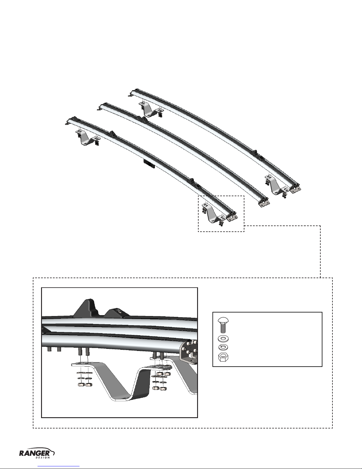
10-460 “V” Foot 4
10-545 Ski Plastic Plug 4
10-548 Hook Protector ( 4 - 3/8" L ) 2
10-721 Mounting Track 2
70-017 Rubber Strip 2
15-2582 Front Crossbow 2
15-2592 Rear Crossbow 1
15-3003 Ladder Clamp Hasp 2
15-3004 Ladder Clamp Rear Hook 2
15-3005 Ladder Clamp Bar ( Driver Side ) 1
15-3006 Ladder Clamp Bar ( Passenger Side ) 1
15-3012 Ski ( Left ) 1
15-3013 Ski ( Right ) 1
15-4290 Front Hook 2
94-1009 Assembly Fastener Kit 1
96-1000 Install Fastener Kit 1
BILL OF MATERIALS
15-300615-3005
15-259215-2582
15-3013
15-3012
15-3004 15-4290
15-3003
10-460 10-545
10-149
10-548
10-721
70-017

For technical support, contact us at 1-800-565-5321 1525-MM Installation Guide |REV. B1 | Page 4
94-1009 Fastener Kit Fastener Assembly
1.1.3 Fastener kits.
4×
#90-487 Carriage Bolt 5/16" × 3/4"
#98-123 Lock Washer
#94-105 Hex Nut
#98-117 Flat Washer
24×
#90-491 Carriage Bolt 5/16" × 1"
#98-123 Lock Washer
#94-105 Hex Nut
#98-117 Flat Washer
4×
#98-123 Lock Washer
#94-105 Hex Nut
#98-117 Flat Washer
2×
#90-491 Carriage Bolt 5/16" × 1"
#98-123 Lock Washer
#94-105 Hex Nut
#98-117 Flat Washer
#98-160 Spacer
# 90-487
4×
Carriage Bolt
5/16"-18 × 3/4"
SS304
# 90-491
26×
Carriage Bolt
5/16"-18 × 1"
SS304
# 98-117
Flat Washer
5/16", O.D 3/4"
SS18-8
34×
# 98-123
Lock Washer
Regular 5/16"
SS304
34×
# 94-105
Hex Nut
5/16"-18
SS316wax
34×
# 98-160 Spacer
SS18-8
2×

For technical support, contact us at 1-800-565-5321 1525-MM Installation Guide |REV. B1 | Page 5
Fastener Assembly96-1000 Fastener Kit
8×
12×
8× # 90-209
Hex Bolt
5/16"-18 × 1"
SS304
8× # 98-117
Flat Washer
5/16", OD 3/4"
SS18-8
# 98-113
12×
Flat Washer
1/4", OD 5/8"
SS18-8
8× # 98-123
Lock Washer
5/16"
SS304
# 98-119
12×
Lock Washer
1/4"
SS304
8× # 94-150 Channel Nut
5/16"
# 90-991
12× Hex Bolt
M6 × 20
#90-991 Hex Bolt M6 × 20
#98-113 Lock Washer
#98-119 Flat Washer
#90-209 Hex Bolt 5/16" × 1"
#98-123 Lock Washer
#98-117 Flat Washer
#94-150 Channel Nut

For technical support, contact us at 1-800-565-5321 1525-MM Installation Guide |REV. B1 | Page 6
PHASE 1 – ASSEMBLY
1.2 LADDER RACK ASSEMBLY
1.2.1 Peel the backer off of the adhesive on the hook protector, then attach the hook protector
to the upper rear hook.
1.2.2 Attach the rear hooks to the ladder clamps, with the pre-assembled hardware on the pivot bars.
TOOLS
qKnife
REMOVE
TOOLS
qCordless Impact
q1/2" Socket
q1/2" Wrench
#90-225 Hex Bolt
5/16" - 18 × 2" SS304
#98-117 Flat Washer
#98-117 Flat Washer
#94-111 Lock Nut
HARDWARE USED
4× hardware is pre-assembled.
2×

For technical support, contact us at 1-800-565-5321 1525-MM Installation Guide |REV. B1 | Page 7
1.2.3 Slide carriage bolts on the bottom face of the crossbows.
DRIVER SIDE PASSENGER SIDE
8×8×
#90-491 Hex Bolt
5/16" × 1" SS304
#90-491 Hex Bolt
5/16" × 1" SS304
Rear crossbow
• Slide 2 pcs. of 3/4" carriage bolts.
• Slide 4 pcs. of 1" carriage bolts.
Rear crossbow
• Slide 2 pcs. of 3/4" carriage bolts.
• Slide 4 pcs. of 1" carriage bolts.
First Front crossbow
• Slide 4 pcs. of 1" carriage bolts.
First Front crossbow
• Slide 4 pcs. of 1" carriage bolts.
HARDWARE USED
2×
HARDWARE USED
2×
#90-487 Carriage Bolt
5/16" × 3/4" SS304
#90-487 Carriage Bolt
5/16" × 3/4" SS304
TIPS: Use tape to keep the bolts from sliding off.
NOTE: The track plug must be removed from the underneath of the front crossbow, and reinstalled
after the feet have been installed in the nal position.

For technical support, contact us at 1-800-565-5321 1525-MM Installation Guide |REV. B1 | Page 8
HARDWARE USED
16× hand-tighten the nuts.
Carriage bolts are already on
the crossbows.
#98-123 Lock Washer
#98-117 Flat Washer
#94-105 Hex Nut
1.2.4 Install the feet on the rst Front, and Rear Crossbows.
NOTE: The more slanted side of the V foot should be closer to the center of the crossbow.

For technical support, contact us at 1-800-565-5321 1525-MM Installation Guide |REV. B1 | Page 9
1.2.5 Fasten the left and right ladder clamp assemblies to the Rear Crossbow.
HARDWARE USED
4×
Carriage bolts are already on
the crossbows.
#98-123 Lock Washer
#98-117 Flat Washer
#94-105 Hex Nut
TOOLS
qCordless Impact q1/2" Socket
qTape Measure qMarker
12 - 3/4"

For technical support, contact us at 1-800-565-5321 1525-MM Installation Guide |REV. B1 | Page 10
8.5"
Tighten the nuts just to hold the front
hook for adjustment.
HARDWARE USED
4× hardware is pre-assembled.
#98-123 Lock Washer
#98-117 Flat Washer
#90-491 Carriage Bolt 5/16" × 1"
#94-105 Hex Nut
TOOLS
qMarker
qCutter
1.2.6 • Pull out the 14.5" track plug on the passenger side of the rst front crossbow and
the driver side of the adjustable front crossbow.
• Loosen the pre-assembled hardware on the front hooks and slide the hooks onto the
front crossbows to the position shown below.
• Cut the track plug, then attach it back to the crossbows.

For technical support, contact us at 1-800-565-5321 1525-MM Installation Guide |REV. B1 | Page 11
1.2.7 Install the left and right Skis to the end brackets of the front crossbow.
HARDWARE USED
4×
Carriage bolts are already on
the ski.
#98-123 Lock Washer
#98-117 Flat Washer
#94-105 Hex Nut
TOOLS
qCordless Impact
q1/2" Socket

For technical support, contact us at 1-800-565-5321 1525-MM Installation Guide |REV. B1 | Page 12
Tighten the nuts just to hold the 2nd
front crossbow for adjustment.
HARDWARE USED
4× hand-tighten the nuts.
#98-123 Lock Washer
#98-117 Flat Washer
#90-491 Carriage Bolt 5/16" × 1"
#94-105 Hex Nut
1.2.8 Install the adjustable front crossbow to the left and right Skis.

For technical support, contact us at 1-800-565-5321 1525-MM Installation Guide |REV. B1 | Page 13
1.2.9 Loosen the pre-assembled hardware on the ladder clamp hasps, slide the hasps on the skis to the
position shown below, and tighten the nuts.
1.2.10 Slide 3pcs. of carriage bolts on the rear end of the each ski, then attach end plugs on
both ends of the skis.
HARDWARE USED
4× hardware is pre-assembled.
#98-123 Lock Washer
#98-117 Flat Washer
#90-487 Carriage Bolt 5/16" × 3/4"
#94-105 Hex Nut
TOOLS
qCordless Impact
q1/2" Socket
qTape Measure
qMarker
HARDWARE USED
6×
#90-491 Carriage Bolt
5/16" × 1" SS304
TOOLS
qMallet
end plug
end plug end plug
15 - 1/2"

For technical support, contact us at 1-800-565-5321 1525-MM Installation Guide |REV. B1 | Page 14
1.2.11 Install the Rear Crossbow to the skis with the clamp handle supports, aligning the rear surface of the
crossbow brackets to the rear surface of the skis.
TOOLS
qCordless Impact
q1/2" Socket
HARDWARE USED
4×
#98-123 Lock Washer
#98-117 Flat Washer
#94-105 Hex Nut
2×
#98-123 Lock Washer
#98-160 Spacer
#98-117 Flat Washer
#94-105 Hex Nut
Carriage bolts are already on
the ski.
Carriage bolts are already on
the ski.

For technical support, contact us at 1-800-565-5321 1525-MM Installation Guide |REV. B1 | Page 15
PHASE 2 – INSTALLATION
2.1 MOUNTING TRACKS INSTALLATION
2.1.1 Pull the plugs off, and apply a bead of silicone around each hole, then install the mounting
tracks on the roof with rubber strips underneath.
TOOLS
qCordless Impact
qT27 Torque Bit
HARDWARE USED
12×
FRONT
NOTE: The ends of the mounting tracks with the half-circles go to the front of the vehicle.
#90-991 Hex Bolt M6 × 20
#98-113 Lock Washer
#98-119 Flat Washer

For technical support, contact us at 1-800-565-5321 1525-MM Installation Guide |REV. B1 | Page 16
PHASE 2 – INSTALLATION
2.2 LADDER RACK INSTALLATION
2.2.1 Position the Ladder Rack ( minimum two persons ) on the vehicle so that the feet are on the tracks.
NOTE: If you do not have a hoist, lift the ladder rack onto the roof manually.
Ladder Rack

For technical support, contact us at 1-800-565-5321 1525-MM Installation Guide |REV. B1 | Page 17
2.2.2 While making sure the crossbows are parallel to each other, slide the rack to the appropriate position,
then attach all the “V” feet to the mounting tracks.
distance < A >
distance < A >
distance < B >
distance < B >
distance < foot to end of track >
TOOLS
qRatchet
q1/2" Socket
qTape Measure
HARDWARE USED
8×
#90-209 Hex Bolt 5/16" × 1"
#98-123 Lock Washer
#98-117 Flat Washer
#94-150 Channel Nut

For technical support, contact us at 1-800-565-5321 1525-MM Installation Guide |REV. B1 | Page 18
2.2.3 Center the crossbows on the vehicle, then tighten all the “V” feet to the crossbows.
TOOLS
qRatchet
q1/2" Socket

For technical support, contact us at 1-800-565-5321 1525-MM Installation Guide |REV. B1 | Page 19
2.2.4 Ladder Rack adjustment for extention ladder.
1"
TOOLS
qCordless Impact
q1/2" Socket
front hook
rear hook
NOTE: The ladder cannot extend beyond the rear bumper of the vehicle.
When the rear hook touches the ladder,
the handle should be 1" below the ladder
clamp hasp.
Now adjust the front hook to be snug against
the ladder rung and tighten the bolts on the
front crossbow.

For technical support, contact us at 1-800-565-5321 1525-MM Installation Guide |REV. B1 | Page 20
2.2.5 Ladder Rack adjustment for stepladder.
NOTE: • The same procedure applies to the hook located on the adjustable front crossbow. The position
of the adjustable front crossbow must be adjusted according to the length of the stepladder.
•The ladder cannot extend beyond the rear bumper of the vehicle.
NOTE: Make sure all the bolts are
tightened after adjusting.
The inner ladder side support must
be adjusted according to the width
of the step ladder.
Be sure that the extrusion of the
step ladder is on the ladder side
support.
IMPORTANT: • After installation is complete, cut the track plug underneath the front crossbow to ll all the
unused space.
• Place the ladder rack warning label on a visible area, recommended on a partition.
Table of contents
Other Ranger Automobile Accessories manuals
Popular Automobile Accessories manuals by other brands

Paravan
Paravan Lancia Voyager user manual

POOL-LINE
POOL-LINE EVO-FIX II ESPECIFIC IRON Assembly instructions

Metra Electronics
Metra Electronics 99-7501 installation instructions

Kuda-Phonebase
Kuda-Phonebase 285190 Installation instruction

Swagman
Swagman XC 2 instruction sheet

Mont Blanc
Mont Blanc MB RoofBar AMC 5121 quick start guide