7. Operation
7.1 Dispensing
For dispensing insert nozzle spout into tank or container to be filled. Operate lever until the nozzle shut off or
the requested level is reached.
Lever can latched.
Do not let nozzle unattended during the dispensing to prevent pollution or damages!
Protect the nozzle after use to prevent damages or hazards.
7.2 Unit Set
Under the state of standby or current charging display, press the button of CAL and RESET at
the same time for 2 seconds. Enter the setting of unit conversion and press the RESET button
choose the measurement unit in turn according to the order of LTR to QTS to PTS to GAL to
LTR meanwhile the accumulated charging quantity will be displayed based on the conversion
of the current measurement unit conversion. Then press the CAL button to quit the unit
conversion setting.
7.3 Clear Reset Partial Total
Press RESET, until LCD displays full screen, wait a few seconds, stop press RESET
The flow meter is ready to clear reset partial total.
7.4 .Example of Factor Calibration
When the flow meter is stable or current charging display ,press CAL for 3 seconds,The flow
meter shows F|ELd.Then press RESET, it shows PErC, then press CAL, we can calibrate the
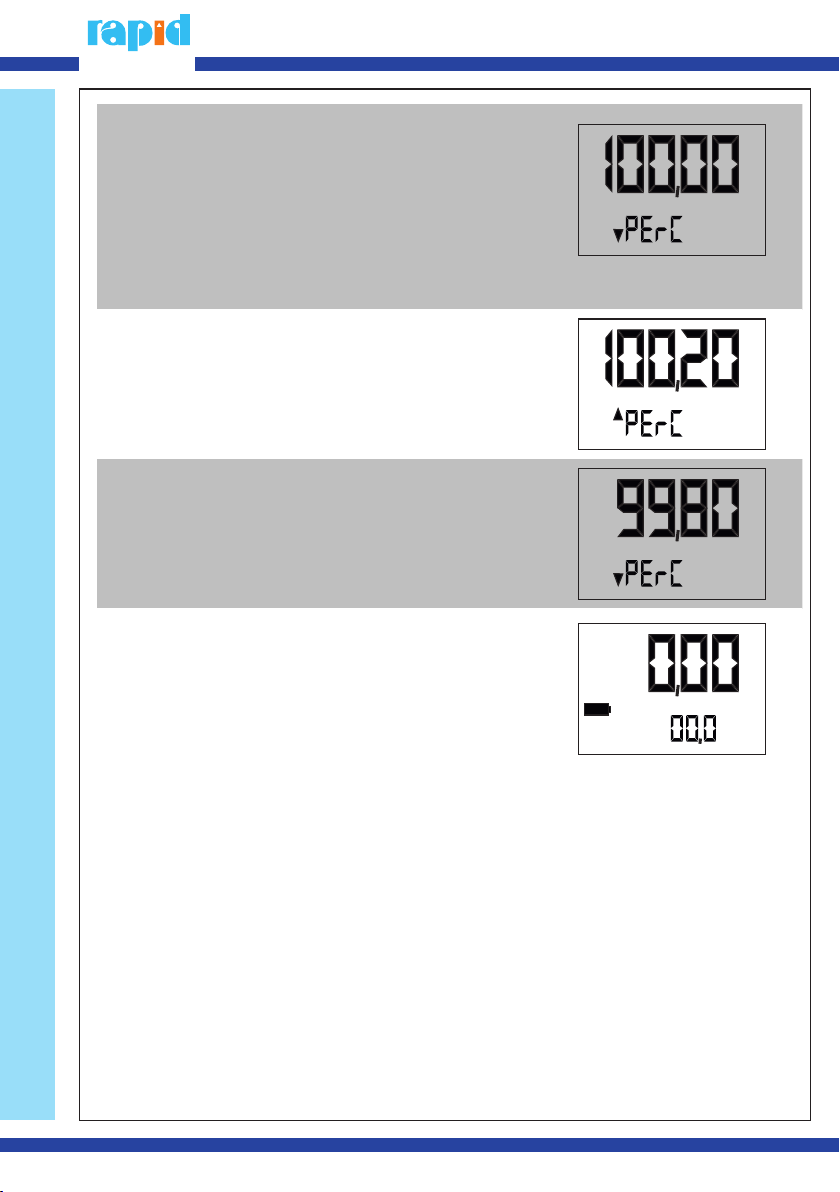
flow meter now. On the left bottom,the flow meter shows PErC. When the
number is blinking, press RESET, so the number will increase.
CAL, the place of edited number changes. Adjus the numbers as the calibration affords it (The
bigger of the Number,the less of the outlet of fuel. Vice versa.) .Press RESET for 3 seconds, the
calibration finishes.The flow meter will return to the partial total and then it shows the partial
total clear
After calibration, the flow meter will use new factor to calculate.
The range of the factor:0.01-655.
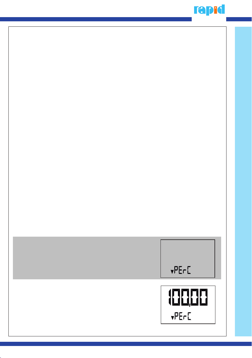
When the flow meter is stable or current
charging display ,press CAL for 3 seconds, it
shows FlELd.Then press RESET,The flow meter
shows PErC.
2 Press CAL,The display shows:
Cal
Cal
+49 (6158) 92980-0
5