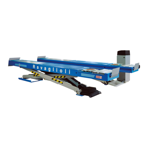
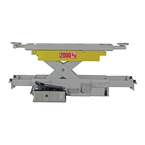
Ravaglioli KP118 User manual

0424-M001-1 Rev. n. 0 (06/17)
KP118 - KP118P
KP118N - KP118NP
KP118Y - KP118PY
TRAVERSA IDRAULICA-PNEUMOIDRAULICA
HYDRAULIC - AIR/HYDRAULIC JACK
PNEUMATISCH-HYDRAULISCHER HEBER
TRAVERSE HYDRAULIQUE - OLEO-PNEUMATIQUE
BARRA TRANSVERSAL NEUMO-HIDRAULICA
Redatto da S.D.T. S.r.l. [DF3N]
0424-M001-1
Per eventuali chiarimenti interpellare il più vicino rivenditore oppure rivolgersi direttamente a:
Servizio assistenza tecnica: RAVAGLIOLI S.p.A - Via 1° Maggio, 3 - 40037 Pontecchio Marconi - Bologna Italia
For any further information please contact your nearest dealer or speak directly to
Technical services: RAVAGLIOLI S.p.A. - Via 1° Maggio, 3 - 40037 Pontecchio Marconi - Bologna Italy
Im Zweifelsfall oder bei Rückfragen wenden Sie sich bitte an den nächsten Händler oder direkt an:
Kundendienst: RAVAGLIOLI S.p.A. - Via 1° Maggio 3, 40037 Pontecchio Marconi - Bologna - Italien
Pour tout renseignement complémentaire, s’adresser au distributeur le plus proche ou directement à:
Service Après-Vente: RAVAGLIOLI S.p.A. - via 1° Maggio 3 - 40037 - Pontecchio Marconi - Bologne - Italie
En caso de dudas, para eventuales aclaraciones, póngase en contacto con el distribuidor más próximo o diríjase
directamente a:
Servicio Post-Venta: RAVAGLIOLI S.p.A. - Via 1° Maggio, 3 - 40037 Pontecchio Marconi - Bologna - Italia

20424-M001-1
SIMBOLOGIA UTILIZZATA NEL MANUALE
SYMBOLS USED IN THE MANUAL
IN DER BEDIENUNGSANLEITUNG VERWENDETE SYMBOLE
SYMBOLES UTILISES DANS LA NOTICE
SIMBOLOGÍA UTILIZADA EN EL MANUAL
SIMBOLI SYMBOLS ZEICHEN SYMBOLES SÍMBOLOS
VIETATO! FORBIDDEN! VERBOTEN! INTERDIT! PROHIBIDO!
Indossare guanti da
lavoro Wear work gloves Arbeitshandschuhe
tragen
Porter des gants de
travail
Colocarse guantes de
trabajo
Calzare scarpe da
lavoro Wear work shoes Arbeitsschuhe tragen Mettre des
chaussures de travail
Usar zapatos de
trabajo
Indossare occhiali di
sicurezza Wear safety goggles Schutzbrille tragen Porter des lunettes de
sécurité
Colocarse gafas de
seguridad
Pericolo di scariche
elettriche Shock hazard Gefahr elektrischer
Entladungen Danger d'électrocution Peligro descargas
eléctricas
Attenzione carichi
sospesi
Caution: hanging
loads
Achtung: Hängende
Lasten
Attention: charges
suspendues
Atención cargas
suspendidas
Pericolo! Attenzione
agli organi meccanici
in movimento
Danger! Moving
mechanical parts
Gefahr! Auf sich in
Bewegung befindliche
Mechanikteile achten
Danger! Organes
mécaniques en
mouvement
Peligro! Partes
mecánicas en
movimiento
Pericolo di
schiacciamento Crushing danger Quetschgefahr Risque d'ecrasement Peligros de aplaste
Obbligo. Operazioni o
interventi da eseguire
obbligatoriamen-
te
Mandatory.
Operations or jobs to
be performed
compulsorily
Pflicht. Obligatorisch
auszuführende
Arbeiten oder
Eingriffe
Obligation.
Opérations ou
interventions à
effectuer
obligatoirement
Obligación.
Operaciones o
intervenciones que
hay que realizar
obligatoriamente
Pericolo! Prestare
particolare attenzione.
Danger! Be particulary
careful
Gefahr! Besondere
Vorsicht üben
Danger! Faire très
attention
Peligro! Prestar
especial atención
Movimentazione con
carrello elevatore o
transpallet
Move with fork lift truck
or transpallet
Transport mit
Gabelstapler oder
Palettenhubwagen
Déplacement avec
chariot élévateur ou
transpalette
Desplazamiento con
carretilla elevadora o
transpallet
Sollevamento dall'alto Lift from above Von oben heben Levage par le haut Elevación por la parte
superior

30424-M001-1
Il presente manuale costituisce parte integrante del prodotto. Dovrà seguire tutta la vita operativa
della traversa. Conservarlo, quindi in un luogo noto e facilmente accessibile e consultarlo ogni
qualvolta sorgano dubbi.
Tutti gli operatori al prodotto devono poter leggere il manuale.
Ogni danno derivante dalla mancata osservanza delle indicazioni contenute nel presente libretto non
sarà addebitabile al costruttore ed esime la RAVAGLIOLI S.p.A. da ogni responsabilità.
This manual is an integral part of the product and must be kept together with the lift throughout the
lifetime of the jack.
Keep the manual in an easily accessible, known place and consult it when in doubt.
All operators must read the manual. The manufacturer shall not be liable for any damage resulting
from incompliance with the instructions contained in this manual. Failure to follow the directions in
the manual shall release RAVAGLIOLI S.p.A. from any liability whatsoever.
Diese Anleitung ist ergänzender Bestandteil des Produkts und muss den Heber über seine gesamte
Standzeit hinweg begleiten. Die Anleitung ist daher an einem bekannten und leicht zugänglichen Ort
aufzubewahren und bei Bedarf zu Rate zu ziehen. Alle Bediener des Produktes müssen zwecks
Einsichtnahme Zugang zur Anleitung haben. Alle Schäden, die auf eine Nichtbeachtung der in dieser
Anleitung enthaltenen Anweisungen zurückzuführen sind, können dem Hersteller nicht angelastet
werden und befreien die Firma RAVAGLIOLI S.p.A. von jeglicher Haftungspflicht.
La présente notice est partie intégrante du produit et doit accompagner toute la vie opérationnelle
de la traverse. Par conséquent, il est nécessaire de la conserver dans un endroit connu et facilement
accessible et être consultée au moindre doute.
Tous les opérateurs qui utilisent ce produit doivent pouvoir lire la notice.
Tout dommage dérivant du non-respect des instructions contenues dans la présente notice décline
la Société RAVAGLIOLI S.p.A. de toute responsabilité.
El presente manual constituye una parte integrante del producto. Tendrá que acompañar toda la vida
operativa de la barra. Conservarlo por lo tanto en un sitio que conozcan todos, al que se pueda
acceder con facilidad, y consultarlo cada vez que surjan dudas.
Todas las personas que utilizan el producto tienen que poder leer el manual. Cualquier daño que
derive de la falta de respeto de las indicaciones que contiene el presente manual exime de toda
responsabilidad a RAVAGLIOLI S.p.A.
ATTENZIONE!
WARNING!
ACHTUNG!
ATTENTION!
¡ATENCIÓN!

40424-M001-1
INDICE
1. DESCRIZIONE E DESTINAZIONE D'USO ............ 11
1.1 Descrizione macchina ............................................ 11
1.2 Destinazione d'uso della macchina ....................... 11
1.3 Comandi della traversa KP118-KP118N-KP118Y 11
1.4 Comandi della traversa KP118P-KP118NP-
KP118PY ................................................................ 11
1.5 Caratteristiche tecniche principali.......................... 13
1.6 Accessori forniti in dotazione ................................ 13
2. ATTIVITÀ SUCCESSIVE AL DISIMBALLO ........... 13
2.1 Movimentazione ..................................................... 13
2.2 Smaltimento e segregazione degli imballi ............ 14
3. INSTALLAZIONE ................................................... 14
3.1 Verifica della completezza delle parti costituenti la
macchina ................................................................ 14
3.2 Verifica dei requisiti minimi richiesti del luogo
di installazione ....................................................... 15
3.3 Connessione pneumatica ...................................... 15
3.4 Installazione KP118-KP118P ................................ 16
3.5 Installazione KP118N-KP118NP-KP118Y-
KP118PY ................................................................ 19
3.6 Primo avviamento della macchina ......................... 20
3.7 Smontaggio ............................................................ 20
4 ISTRUZIONI PER L'USO ....................................... 21
4.1 Precauzioni per l'uso e addestramento
del personale preposto all'utilizzo ......................... 21
4.2 Spiegazione comandi ............................................ 23
4.2.1 Comandi KP118-KP118N-KP118Y ....................... 24
4.2.2 Comandi KP118P-KP118NP-KP118PY ................ 25
CONTENTS
1. DESCRIPTION AND PURPOSE ............................ 11
1.1 Machine description ............................................... 11
1.2 Purpose of the equipment ...................................... 11
1.3 Jack controls KP118-KP118N-KP118Y ................. 11
1.4 Jack controls - KP118P-KP118NP-KP118PY........ 11
1.5 Main specifications ................................................. 13
1.6 Optional supplied accessories ............................... 13
2. AFTER UNPACKING ............................................. 13
2.1 Handling ................................................................. 13
2.2 Disposal of packing material .................................. 14
3. INSTALLATION ...................................................... 14
3.1 Pre-installation check ............................................. 14
3.2 Checking the minimum requirements of the
place of installation ................................................ 15
3.3 Air connection ........................................................ 15
3.4 Installation KP118-KP118P ................................... 16
3.5 Installation KP118N-KP118NP-KP118Y-KP118PY19
3.6 First start-up ............................................................ 20
3.7 Disassembly ........................................................... 20
4 OPERATING INSTRUCTIONS ............................... 21
4.1 Safety precautions and operator training .............. 21
4.2 Description of controls............................................ 23
4.2.1 Controls KP118-KP118N-KP118Y ........................ 24
4.2.2 Controls KP118P-KP118NP-KP118PY ................. 25
INHALT
1. BESCHREIBUNG UND BESTIMMUNGSGEMÄSSE
VERWENDUNG ..................................................... 11
1.1 Beschreibung der Einrichtung ............................... 11
1.2 Bestimmungsgemässe Verwendung der
Einrichtung ............................................................. 11
1.3 Steuerungen des Hebers KP118-KP118N-KP118Y 11
1.4 Steuerungen des Hebers KP118P-KP118NP-
KP118PY ................................................................ 11
1.5 Technische Haupteigenschaften ........................... 13
1.6 Mitgelieferten Zubehör auf Anfrage ....................... 13
2. ARBEITSVORGÄNGE NACH DEM AUSPACKEN13
2.1 Transport ................................................................ 13
2.2 Entsorgung der Verpackungsteile ......................... 14
3. AUFSTELLUNG ..................................................... 14
3.1 Vollständigkeitskontrolle der Einrichtungsteile ..... 14
3.2 Kontrolle der Mindesterfordernisse des
Aufstellungsorts ...................................................... 15
3.3 Pneumatischer Anschluss ...................................... 15
3.4 Installation KP118-KP118P ................................... 16
3.5 Installation KP118N-KP118NP-KP118Y-KP118PY 19
3.6 Erste Inbetriebsetzung der Einrichtung ................. 20
3.7 Ausbau ................................................................... 20
4. ANWEISUNGEN FÜR DIE BEDIENUNG .............. 21
4.1 Vorsichtsmassnahmen und Schulung des
Bedienpersonals .................................................... 21
4.2 Beschreibung der Steuerungen ............................. 23
4.2.1 Steuerungen KP118-KP118N-KP118Y ................. 24
4.2.2 Steuerungen KP118P-KP118NP-KP118PY .......... 25
SOMMAIRE
1. DESCRIPTION ET UTILISATION CONFORME ..... 11
1.1 Description de la machine ....................................... 11
1.2 Utilisation conforme de la machine ....................... 11
1.3. Commandes de la traverse KP118-KP118N-KP118Y11
1.4 Commandes de la traverse KP118P-KP118NP-
KP118PY ................................................................ 11
1.5 Principales spécifications techniques ..................... 13
1.6 Accessoires sur demande livres en dotation ......... 13
2. OPERATIONS SUCCESSIVES AU DEBALLAGE 13
2.1 Déplacement .......................................................... 13
2.2 Traitement et élimination des emballages ............. 14
3. INSTALLATION ...................................................... 14
3.1 Contrôle de l’intégrité des différentes pièces de la
machine .................................................................. 14
3.2 Contrôle des caractéristiques minimes requises
pour la zone d’installation ...................................... 15
3.3 Connexion pneumatique ....................................... 15
3.4 Installation KP118-KP118P ................................... 16
3.5 Installation KP118N-KP118NP-KP118Y-KP118PY19
3.6 Première mise en service de la machine .............. 20
3.7 Démontage............................................................. 20
4. MODE D’EMPLOI ................................................... 21
4.1 Précautions pour l’emploi et formation du personnel
préposé à l’utilisation ............................................. 21
4.2 Description des commandes ................................. 23
4.2.1 Commandes KP118-KP118N-KP118Y ................. 24
4.2.2 Commandes KP118P-KP118NP-KP118PY .......... 25
5. DISPOSITIFS DE SECURITE ................................. 26
5.1 Instructions ............................................................. 26
5.2 Soupape de sûreté en cas de rupture des tuyaux . 27
ÍNDICE
1. DESCRIPCIÓN Y DESTINACIÓN DE USO ........... 11
1.1 Descripción de la máquina .................................... 11
1.2 Destino de uso de la máquina ............................... 11
1.3 Mandos de la barra transversal KP118-KP118N-
KP118Y .................................................................. 11
1.4 Mandos de la barra transveral KP118P-KP118NP-
KP118PY ................................................................ 11
1.5 Características técnicas principales ...................... 13
1.6 Accesorios suministrados en dotacion .................. 13
2. ACTIVIDADES SUCESIVAS AL DESEMBALAJE 13
2.1 Desplazamiento ..................................................... 13
2.2 Eliminación y segregación de los embalajes ........ 14
3. INSTALACIÓN ....................................................... 14
3.1 Comprobación de la integridad de las partes que
constituyen la máquina. ......................................... 14
3.2 Comprobación de los requisitos mínimos
que requiere el sitio de la instalación. ................... 15
3.3 Conexión neumática .............................................. 15
3.4 Instalación KP118-KP118P ................................... 16
3.5 Instalación KP118N-KP118NP-KP118Y-KP118PY19
3.6 Primera puesta en marcha de la máquina ............ 20
3.7 Desmontaje ............................................................ 20
4. MODO DE EMPLEO ............................................... 21
4.1 Precauciones para usar la máquina y para
formar al personal autorizado para su utilización . 21
4.2 Explicación de los mandos .................................... 23
4.2.1 Mandos KP118-KP118N-KP118Y ......................... 24
4.2.2 Mandos KP118P-KP118NP-KP118PY .................. 25
5. DISPOSITIVOS DE SEGURIDAD .......................... 26
5.1 Advertencias........................................................... 26

50424-M001-1
ZUSAMMENSETZUNG
DER ANLEITUNG
52 Seiten (inkl.
Deckblätter)
COMPOSITION DE LA
NOTICE
52 pages (pages de la
couverture incluses)
COMPOSICIÓN DEL
MANUAL
52 páginas (incluidas
las portadas)
COMPOSITION OF
MANUAL
52 pages (including
cover pages)
COMPOSIZIONE
DEL MANUALE
52 pagine (copertine
comprese)
5. DISPOSITIVI DI SICUREZZA ................................. 26
5.1 Avvertenze.............................................................. 26
5.2 Valvola di sicurezza rottura tubi ............................. 27
5.3 Dispositivo contro il sovraccarico .......................... 27
5.4 Dispositivo di arresto meccanico ........................... 27
6. MANUTENZIONE ................................................... 27
6.1 Ripristino livello olio KP118-KP118N-KP118Y ..... 28
6.2 Sostituzione completa olio centralina KP118-
KP118N-KP118Y ................................................... 28
6.3 Cambio olio KP118P-KP118NP-KP118PY ........... 29
7. ACCANTONAMENTO ........................................... 31
8. ROTTAMAZIONE ................................................... 31
9. TABELLA RICERCA GUASTI ............................... 32
9.1 Modelli KP118 - KP118N - KP118Y ....................... 32
9.2 Modelli KP118P - KP118NP - KP118PY ............... 32
10. TAVOLE RICAMBI ................................................. 40
10.1 Come ricevere i ricambi ......................................... 40
10.2 Indice tavole ricambi .............................................. 40
11. VERIFICHE DI INSTALLAZIONE E PERIODICHE 46
12. TARGHETTA DI IDENTIFICAZIONE ..................... 52
5. SAFETY DEVICES ................................................. 26
5.1 Warning .................................................................. 26
5.2 Leaking line safety valve ........................................ 27
5.3 Overload safety ...................................................... 27
5.4 Mechanical safety lock ........................................... 27
6. MAINTENANCE ..................................................... 27
6.1 Topping up oil level KP118-KP118N-KP118Y ...... 28
6.2 Changing oil in the power unit KP118-KP118N-
KP118Y .................................................................. 28
6.3 Changing oil - KP118P-KP118NP-KP118PY ........ 29
7. STORAGE .............................................................. 31
8. DISPOSAL.............................................................. 31
9. TROUBLESHOOTING TABLE ............................... 33
9.1 Model KP118 - KP118N - KP118Y ........................ 33
9.2 Model KP118P - KP118NP - KP118PY ................. 33
10. SPARE PARTS TABLES ....................................... 40
10.1 How to order spare parts ........................................ 40
10.2 Spare parts summary ............................................. 40
11. INSTALLATION AND PERIODIC INSPECTIONS . 46
12. IDENTIFICATIONPLATE ....................................... 52
5. SICHERHEITSEINRICHTUNGEN ......................... 26
5.1 Hinweise................................................................. 26
5.2 Sicherheitsventil bei Leitungsbruch....................... 27
5.3 Einrichtung gegen Überlast ................................... 27
5.4 Mechanische Arretiereinrichtung ........................... 27
6. WARTUNG ............................................................. 27
6.1 Wiederherstellen des Ölstands KP118-KP118N-
KP118Y ................................................................... 28
6.2 Kompletter Ölwechsel im Hydraulikaggregat
KP118-KP118N-KP118Y ....................................... 28
6.3 Ölwechsel KP118P-KP118NP-KP118PY .............. 29
7. EINLAGERUNG ..................................................... 31
8. VERSCHROTTUNG ............................................... 31
9. TABELLE STÖRUNGSSUCHE ............................. 34
9.1 Modell KP118 - KP118N - KP118Y ....................... 34
9.2 Modell KP118P - KP118NP - KP118PY ................ 34
10. ERSATZTEILETAFELN ......................................... 40
10.1 Anweisungen für Ersatzteileaufträge ..................... 40
10.2 Tafelverzeichnis ..................................................... 40
11. KONTROLLEN DER ERSTINSTALLATION UND
REGELMÄSSIGE KONTROLLEN ......................... 46
12. IDENTIFIKATIONSSCHILD ................................... 52
5.3 Dispositif contre les surcharges ............................. 27
5.4 Dispositif d’arrêt mécanique .................................. 27
6. ENTRETIEN ........................................................... 27
6.1 Rétablissement du niveau de l’huile KP118-
KP118N-KP118Y ................................................... 28
6.2 Vidange de l’huile de l’unité de contrôle KP118-
KP118N - KP118Y.................................................. 28
6.3 Changement de l’huile KP118P-KP118NP-
KP118PY ................................................................ 29
7. STOCKAGE ........................................................... 31
8. MISE A LA FERRAILLE ......................................... 31
9. TABLEAU POUR L’IDENTIFICATION DES PANNES35
9.1 Modèles KP118 - KP118N - KP118Y .................... 35
9.2 Modèles KP118P - KP118NP - KP118PY ............. 35
10. TABLES DES PIECES DE RECHANGE ............... 40
10.1 Comment procéder pour recevoir les pièces de
rechange ................................................................ 40
10.2 Sommaire planches ............................................... 40
11. CONTROLES A REALISER LORS DE
L’INSTALLATION ET PERIODIQUEMENT ............ 46
12. PLAQUE D’IDENTIFICATION ................................ 52
5.2 Válvula de seguridad en caso de rotura de tubos . 27
5.3 Dispositivo contra la sobrecarga ........................... 27
5.4 Dispositivo de parada mecánica ........................... 27
6. MANTENIMIENTO .................................................. 27
6.1 Restablecimiento del nivel del aceite KP118-
KP118N-KP118Y ................................................... 28
6.2 Sustitución completa aceite central
KP118-KP118N-KP118Y ....................................... 28
6.3 Cambio del aceite KP118P-KP118NP-KP118PY . 29
7. DESUSO ................................................................. 31
8. REDUCCIÓN A RESIDUOS .................................. 31
9. TABLA BÚSQUEDA AVERÍAS............................. 36
9.1 Modelos KP118 - KP118N - KP118Y .................... 36
9.2 Modelos KP118P - KP118NP - KP118PY ............. 36
10. REPUESTOS .......................................................... 40
10.1 Como recibir los repuestos .................................... 40
10.2 Índice tablas ........................................................... 40
11. CONTROLES DE INSTALACION Y
INSPECCIONES PERIODICAS ............................. 46
12. PLACA DE IDENTIFICACION ............................... 52

60424-M001-1
2
21
43
ADESIVI E DISPOSITIVI SEGNALAZIONE DI PERICOLO
WARNING LABELS AND PLATES
RIF.
REF
CODICE
CODE
DESCRIZIONE
DESCRIPTION
APPLICAZIONE
APPLICATION
1 999910040 Targhetta portata kg
13500
Rated load plate -
13500 kg
TUTTI I MODELLI — ALL MODELS (*)
2 Targa matricola Number plate
3 99990726 Targhetta istruzioni Instructions plate
4 999911340 Tabella istruzioni
fissaggio
Installation instructions
label
5 99990114 Targhetta freccia Arrow plate
51 53
4
1
5
KP118 - KP118 N - KP118 Y KP118 P - KP118 NP - KP118 PY

70424-M001-1
WARNING!
For a correct handling of residual risks, pictograms are located
on the machine to show the areas subject to risk during operation.
These indications are supplied on self-sticking labels bearing
an identification code.
Important: should the labels be lost or become illegible, please
order replacements from the manufacturer and attach them as
shown in the diagram above.
ACHTUNG!
Für eine korrekte Verhaltensweise bei den noch bestehenden
Risiken zeigen Bilderschriftzeichen auf der Ausrüstung an,
welche Zonen während des Betriebs Gefahrenquellen
darstellen könnten.
Diese Hinweise finden Sie auf Selbstklebeetiketten, die über
eine eigene Identifikationscode verfügen.
Wichtig: Bei Verlust oder Unleserlichkeit der Etiketten bestellen
Sie diese bitte bei der Herstellerfirma und bringen sie gemäss
dem oben aufgeführten Schema an.
ATTENTION!
Pour assurer une gestion correcte des risques résiduels, des
pittogrammes sont appliqués sur la machine pour signaler les
zones susceptibles de risque en phase de fonctionnement.
Ces informations sont fournies sur des étiquettes autocollantes
qui portent chacune un code d'identification.
Important: en cas de perte des étiquettes ou si elles deviennent
illisibles, les commander directement chez le fabricant et les
appliquer sur la machine en suivant le schéma ci-dessus.
ATENCIÓN!
Con el fin de una correcta gestión de los riesgos residuos, están
colocados en la máquina pitogramas para el relievo de las
zonas suceptibles de riesgo en fase operativa.
Estas indicaciones se abastecen en etiquetas autoadhesivas
que tienen un propio código de identificación.
Importante: en el caso que las etiquetas se perdieran o se
volvieran invisibles se ruega pedirlas a la casa constructora y
volverlas a colocar según el esquema arriba indicado.
ATTENZIONE!
Ai fini di una corretta gestione dei rischi residui sono ricollocati
sulla macchina pittogrammi per il rilievo di quelle zone suscet-
tibili di rischio in fase operativa. Queste indicazioni sono fornite
su etichette autoadesive che recano un proprio codice di
identificazione.
Importante: nel caso in cui le etichette venissero smarrite o
diventassero illeggibili, si prega di ordinarle alla casa costruttrice
e ricollocarle secondo lo schema sopra riportato.

8 0424-M001-1
KP118P
KP118
KP118NP
KP118N
DATI TECNICI
TECHNICAL SPECIFICATIONS
KP118 - KP118 N - KP118
Y
KP118 P - KP118 NP - KP118 PY
Portata - Capacity 13.500 kg 13.500 kg
Pressione max olio - Max oil
pressure
160 bar 160 bar
Emissione sonora - Noise level <70 dB (A) <70 dB (A)
Peso - Weight 150 kg 150 kg
Pressione aria - Air pressure - 6 ÷ 10 bar

90424-M001-1
DATI TECNICI (TUTTI I MODELLI)
TECHNICAL SPECIFICATIONS (ALL MODELS)
Tempo di salita pistone singolo - Rise time of single piston 22”
Tempo di discesa pistone singolo — Descent time of single piston 25”
Tempo di salita due pistoni - Rise time of two pistons 35”
Tempo di discesa due pistoni - Descent time of two piston 35”
NOTA: I tempi sono stati rilevati senza carico (a vuoto)
NOTE: Times are detected without load (empty)

10 0424-M001-1
KP118 P - KP118 NP - KP118 PY
B
A
Pistoni di sollevamento
Lifting pistons
Hubzylinder
Pistons de levage
Pistones de elevación
Ruota di scorrimento
Sliding wheel
Gleitrad
Roue de coulissement
Rueda de deslizamiento
Sfilo sostegno traversa
Wheel free jack support plate
Ausziehvorrichtung Heberstütze
Extension du support de la traverse
Extensión sostén travesaño
Pompa idraulica manuale
Manual hydraulic pump
Manuelle Hydraulikpumpe
Pompe hydraulique manuelle
Bomba hidráulica manual
KP118 - KP118 N - KP118 Y
Fig. 1
C
Ghiere per arresto meccanico
Lock ring nuts
Arretiernutmuttern
Bagues d'arrêt mécanique
Casquillos de parada
D
Ghiere per arresto meccanico
Lock ring nuts
Arretiernutmuttern
Bagues d'arrêt mécanique
Casquillos de parada
Fig. 2
Pannello di comando
Control panel
Bedientafel
Tableau de commande
Panel de control
C
B
E
A
D

110424-M001-1
1. DESCRIZIONE E DESTINAZIONE D'USO
1.1 Descrizione macchina
- Traverse a funzionamento idraulico (vedi Fig. 1) versione
KP118 - KP118N - KP118Y;
- Traverse a funzionamento pneumo-idraulico (vedi Fig. 2)
versione KP118P - KP118NP - KP118PY.
1.2 Destinazione d'uso della macchina
La traversa è destinata al supporto e sollevamento dei veicoli,
quando questi sono già sostenuti su un ponte sollevatore
appositamente predisposto. Il carico massimo è indicato sulla
targa e corrisponde alla massima portata della traversa. Per la
compatibilità della traversa con il sollevatore sul quale deve
essere usata e per le procedure di installazione, contattare
sempre il servizio assistenza del costruttore.
1.3 Comandi della traversa KP118-KP118N-KP118Y
Con rif. a Fig. 1:
Avalvola manuale per salita indipendente pistone sinistro
Bvalvola manuale per salita indipendente pistone destro
Cvalvola manuale per scarico olio - comando discesa
traversa
Dleva manuale comando salita traversa
1.4 Comandi della traversa KP118P-KP118NP-KP118PY
Con rif. a Fig. 2:
Apulsante di discesa
Bpulsante di salita
Cpulsante scarico condensa
Dvalvola manuale per salita indipendente pistone sinistro
Evalvola manuale per salita indipendente pistone destro
1. BESCHREIBUNG UND BESTIMMUNGSGEMÄSSE
VERWENDUNG
1.1 Beschreibung der Einrichtung
- Hydraulisch betriebener Heber(siehe Abb.1),Ausführung KP118-
KP118N-KP118Y;
- Hydraulisch-pneumatisch betriebener Heber (siehe Abb. 2),
Ausführungen KP118P - KP118NP - KP118PY.
1.2 Bestimmungsgemässe Verwendung der Einrichtung
Heber zum Heben und Stützen von Fahrzeugen, die bereits von
einerzumEinbauvonHebernvorgesehenen Hebebühne gestützt
werden.Diemax.zugelasseneLastistaufdemSchild angegeben
und entspricht der max. Tragfähigkeit des Hebers. Hinsichtlich
der Kompatibilität des Hebers mit der Hebebühne auf die er
montiert werden soll und dem Einbauverfahren stets den
Kundendienst des Herstellers zu Rate ziehen.
1.3 Steuerungen des Hebers KP118-KP118N-KP118Y
Zu Abb. 1:
AManuelles Ventil für den unabhängigen Hub des linken Kolbens
BManuelles Ventil für den unabhängigen Hub des rechten
Kolbens
CManuelles Ventil für Ölablass / Steuerung der Hebersenkung
DManueller Hbel zur Steuerug des Heberanstiegs
1.4 Steuerungen des Hebers KP118P-KP118NP-KP118PY
Zu Abb. 2:
ATaster „Heben“
BTaster „Senken“
CTaster Kondenswasserablass
DManuelles Ventil für den unabhängigen Hub des linken
Kolbens
EManuelles Ventil für den unabhängigen Hub des rechten
Kolbens
1. DESCRIPTION AND PURPOSE
1.1 Machine description
- Hydraulic jack (see fig. 1) version KP118 - KP118N - KP118Y;
- Air/hydraulic jack (see fig. 2) version KP118P - KP118NP -
KP118PY.
1.2 Purpose of the equipment
The wheel free jack is designed to support and lift vehicles when
these are already supported on a lift. The maximum load is
shown on the rating plate and corresponds to the maximum
lifting capacity of the wheel free jack. Always contact the
manufacturer’s after sales department for details relating to the
compatibility of the wheel free jack with the lift on which it is to be
used and for installation instructions.
1.3 Jack controls KP118-KP118N-KP118Y
See Fig. 1
AManual valve for lifting left piston
BManual valve for lifting right piston
CManual valve: controls oil drain / lowers wheel free jack
DManual lever: lowers wheel free jack
1.4 Jack controls - KP118P-KP118NP-KP118PY
See Fig. 2
ADown button
BUp button
CCondensation drain button
DManual valve to lift left piston
EManual valve to lift right piston
1.3. Commandes de la traverse KP118-KP118N-KP118Y
Référence Fig. 1:
AVanne manuelle de montée indépendante du piston gauche
BVanne manuelle de montée indépendante du piston de
droite
CVanne manuelle de vidange huile - commande de la course
de descente de la traverse
Dlevier de commande manuelle de la montée de la traverse
1.4 CommandesdelatraverseKP118P-KP118NP-KP118PY
Référence Fig. 2:
Apoussoir de montée
Bpoussoir de descente
Cpoussoir de décharge de l’eau de condensation
Dvanne manuelle de montée indépendante du piston gauche
Evanne manuelle de montée indépendante du piston de droite
1. DESCRIPCIÓN Y DESTINACIÓN DE USO
1.1 Descripción de la máquina
- Travesaño con funcionamiento hidráulico (véase Fig. 1)
versión KP118 - KP118N - KP118Y.
- Travesaño con funcionamiento neumo-hidráulico (véase
Fig. 2) versión KP118P - KP118NP - KP118PY.
1.2 Destino de uso de la máquina
La barra transversal ha sido ideada para soportar y elevar los
vehículos, cuando ya se encuentren colocados en un puente
elevador predispuesto. La placa de características señala la
carga máxima que corresponde a la capacidad máxima del
travesaño. Para las modalidades de instalación de la barra y para
su compatibilidad con el puente elevador en el que tiene que ser
instalada, dirígasealserviciode asistenciatécnicadelconstructor.
1.3 MandosdelabarratransversalKP118-KP118N-KP118Y
Con Ref. en Fig. 1:
AVálvula manual para subida independiente pistón izquierdo
BVálvula manual para subida independiente pistón derecho
CVálvula manual para descarga aceite-mando bajada
travesaño
DPalanca manual mando subida travesaño
1.4 Mandos de la barra transveral KP118P-KP118NP-
KP118PY
Con Ref. en Fig. 2:
APulsador de bajada
BPulsador de subida
CPulsador de descarga condensación
DVálvula manual para subida independiente pistón izquierdo
EVálvula manual para subida independiente pistón derecho
1. DESCRIPTION ET UTILISATION CONFORME
1.1 Description de la machine
- Traverses à fonctionnement hydraulique (voir Fig. 1), version
KP118 - KP118N - KP118Y;
- Traverses à fonctionnement oléo-pneumatique (voir Fig. 2),
version KP118P - KP118NP - KP118PY.
1.2 Utilisation conforme de la machine
La traverse est destinée au support et au levage des véhicules
lorsque ces derniers se trouvent déjà sur un pont élévateur
spécialement conçu. La charge maximale est indiquée sur la
plaque et correspond à la portée maximale de la traverse. En ce
qui concerne la compatibilité de la traverse avec le pont élévateur
sur lequel elle doit être utilisée et les procédures d’installation,
s’adresser toujours au Service Après-Vente du fabricant.

12 0424-M001-1
Tabella 1
Fig. 3
A
B
AB
Descrizione
Description
Beschreibung
Description
Des
c
ri
p
ci
ó
n
Codice
Code
Code
Référenc
C
ó
di
g
o
Accessorio
Accessory
Zubehör
Accessoire
Accesorio
A- Distanziale corto per traversa
A- Free wheel jack short spacer
A - kurzes Distanzst
ück für
heber
A- Entretoise courte pour traverse
A- Distanciadorcorto para traviesa
042401271
B- Distanziale lungo per traversa
B- Free wheel jack long spacer
B- langes Distanzst
ück für
heber
B- Entretoiselongue pour traverse
B- Distanciadorlargo para traviesa
042401281
lnsieme piattello
Plate assembly
Mit Platte
Ensembleplateau
Grupo platillo
042401151
A- Prolunga lunga
A- Long adaptor
A- Verlängerunglang
A- Rallonge longue
A- Prolongación larga
042401201
B- Prolunga corta
B- Short adaptor
B- Verlängerungkurz
B- Rallonge courte
B- Prolongacióncorta
042401191

130424-M001-1
1.5 Caratteristiche tecniche principali
- Valvola di sicurezza nei confronti di sovraccarichi
- Valvola di sicurezza rottura tubi
- Rulli o sfere per scorrimento/posizionamento traversa sul
ponte.
1.6 Accessori forniti in dotazione
Con riferimento alla Tabella 1 è possibile individuare i tipi di
accessori che possono essere utilizzati sui prodotti trattati in
questo manuale.
1.5 Main specifications
- Overload safety valve
- Failed line safety valve
- Rollers or balls for sliding/positioning the wheel free jack on
the lift.
1.6 Optional supplied accessories
Refer to Table 1 for the optional accessories which can be fitted
to the equipment discussed in this manual.
1.5 Technische Haupteigenschaften
- Sicherheitsventil bei Überlast
- Sicherheitsventil bei Leitungsbruch
- Rollen oder Kugeln zur Gleitung / Positionierung des Hebers
auf der Hebebühne
1.6 Mitgelieferten Zubehör auf Anfrage
In der Tabelle 1 ist das mit den in diesem Bedienungshandbuch
beschriebenen Produkten verwendbare Zubehör angegeben.
1.5 Principales spécifications techniques
- Soupape de sûreté contre les surcharges.
- Soupape de sûreté contre la rupture des tuyaux.
- Rouleaux ou billes de coulissement/positionnement de la
traverse sur le pont.
1.6 Accessoires sur demande livres en dotation
Le Tableau 1 montre tout type d’accessoire pouvant être utilisé
sur les produits décrits dans cette notice.
1.5 Características técnicas principales
- Válvula de seguridad con respecto a las sobrecargas
- Válvula de seguridad rotura tubos
- Rodillos o bolas para deslizamiento/colocación travesaño
en el puente.
1.6 Accesorios suministrados en dotacion
Referencia Tabla 1. Es posible localizar los tipos de accesorios
que pueden utilizarse en los productos indicados en el presente
manual.
2. ATTIVITÀ SUCCESSIVE AL DISIMBALLO
2.1 Movimentazione
Per lo spostamento della macchina nel punto prescelto per
l'installazione (o per una successiva ridisposizione) assicurar-
si di :
- sollevare la macchina mediante l'uso di carrello elevatore
(gru) posizionando le brache come indicato in Fig.3;
- indossare gli indumenti e le protezioni individuali (guanti
protettivi e scarpe antinfortunistiche);
- i mezzi di sollevamento devono avere resistenza e caratteri-
stiche idonee al sostegno del carico sollevato.
2. AFTER UNPACKING
2.1 Handling
Follow the instructions below whemo moving the equipment to
the designated place of installation (or when relocating it):
- use a fork-lift truck (crane) to handle the equipment placed in
a sling as shown in Fig.3 ;
- wear personal protection equipment and clothing (gloves and
safety shoes);
- make sure the lifting equipment specifications meet or exceed
the load to be handled.
2. ARBEITSVORGÄNGE NACH DEM AUSPACKEN
2.1 Transport
Für die Transportmanöver der Einrichtung zum vorgesehenen
Aufstellungsort(oderbei weiteren Transportmanövern) folgende
Punkte beachten:
- die Einrichtung mit einem Gabelstapler (Kran) anheben und
die Seile gemäss Abb. 3 positionieren.
- Der auszuführenden Arbeit angemessene Kleidung und
individuelleSchutzvorrichtungentragen(Schutzhandschuhe,
Arbeitsschutzschuhe).
- DieTragfähigkeiten und Eigenschaften der
Lastaufnahmemittel müssen zum Stützen der gehobenen
Last geeignet sein.
2. OPERATIONS SUCCESSIVES AU DEBALLAGE
2.1 Déplacement
Pour déplacer la machine à l’endroit choisi pour son installation
(ou pour toute réinstallation successive) s’assurer:
- de soulever la machine à l'aide d'un chariot élévateur (grue)
en positionnant les bras comme indiqué à la Fig.3;
- de porter des vêtements et des protections individuelles
(gants et chaussures de protection);
- d’utiliser des moyens de levage ayant une résistance et des
caractéristiques suffisantes pour supporter la charge
soulevée.
2. ACTIVIDADES SUCESIVAS AL DESEMBALAJE
2.1 Desplazamiento
Para el desplazamiento de la máquina al punto elegido para la
instalación (o para una sucesiva colocación), es necesario:
- elevarlamáquina mediante el carro elevador (grua) colocando
las eslingas como indica la Fig.3 ;
- llevar prendas y protecciones individuales (guantes
protectivos y zapatos de seguridad);
- los medios de elevación deben tener resistencia y
características idóneas al sostén de la carga elevada.

RISERVATO AL PERSONALE AUTORIZZATO ALL'INSTALLAZIONE - ONLY FOR INSTALLATION-AUTHORIZED STAFF
IST DEM ZUR INSTALLATION AUTORISIERTEN PERSONAL VORBEHALTEN - SEULEMENT POUR LE PERSONNEL AUTORISE A L'INSTALLATION - RESERVADO AL PERSONAL ENCARGADO DE LA INSTALACION
14 0424-M001-1
Fig. 4
KP118 P - KP118 NP
2.2 Smaltimento e segregazione degli imballi
Rimuovere i componenti degli imballi e riporli in appositi luoghi
di raccolta inaccessibili a personale non autorizzato, bambini
e animali.
3. INSTALLAZIONE
3.1 Verifica della completezza delle parti costituenti la
macchina
Prima di iniziare l'installazione accertarsi di avere ricevuto le
parti necessarie ad assemblare ed installare il prodotto corret-
tamente (verificare con le tavole ricambi).
2.2 Disposal of packing material
Remove all packing materials and store them in suitable
collectionareasbanningaccess to unauthorised people, children
and animals.
3. INSTALLATION
3.1 Pre-installation check
Before installation, make sure all the necessary parts for
assembling and installing the equipment were included in the
consignment (check with the spare parts tables).
2.2 Entsorgung der Verpackungsteile
Die Verpackungsteile abnehmen und an einem für Unbefugte,
Kinder und Tiere unzugänglichen Sammelplatz aufbewahren.
3. AUFSTELLUNG
3.1 Vollständigkeitskontrolle der Einrichtungsteile
Vor der Aufstellung sicherstellen, dass alle Teile, die dazu
dienen, die Einrichtung fachgemäss zusammenzubauen und
aufzustellen im Lieferumfang enthalten sind (anhand der
Ersatzteillisten überprüfen).
2.2 Traitement et élimination des emballages
Retirer les emballages et les déposer dans des endroits de
ramassage spéciaux inaccessibles au personnel non autorisé,
aux enfants et aux animaux.
3. INSTALLATION
3.1
Contrôle de l’intégrité des différentes pièces de la machine
Avant de commencer l’installation, s’assurer d’avoir bien reçu
touteslesparties nécessaires pour pouvoir assembleretinstaller
le produit correctement (pour faciliter le contrôle, utiliser les
planches des pièces de rechange).
2.2 Eliminación y segregación de los embalajes
Una vez que se han quitado las distintas partes del embalaje,
hay que ponerlas en los correspondientes sitios de recogida,
que no tendrán que estar al alcance de las personas no
autorizadas, de niños o animales.
3. INSTALACIÓN
3.1 Comprobación de la integridad de las partes que
constituyen la máquina.
Antesdeempezarainstalarlamáquinahayqueasegurarsedehaber
recibido las partes necesarias para ensamblar y para instalar el
productocorrectamente(comprobar conlastablasderecambios).

RISERVATO AL PERSONALE AUTORIZZATO ALL'INSTALLAZIONE - ONLY FOR INSTALLATION-AUTHORIZED STAFF
IST DEM ZUR INSTALLATION AUTORISIERTEN PERSONAL VORBEHALTEN - SEULEMENT POUR LE PERSONNEL AUTORISE A L'INSTALLATION - RESERVADO AL PERSONAL ENCARGADO DE LA INSTALACION
150424-M001-1
3.2 Verifica dei requisiti minimi richiesti del luogo di
installazione
Accertarsi che il luogo ove poi verrà installata la macchina sia
conforme alle seguenti caratteristiche:
- illuminazione sufficiente (ma luogo non sottoposto ad
abbagliamenti o luci intense);
- luogo non esposto alle intemperie;
- ambiente privo di inquinanti;
3.3 Connessione pneumatica
La pressione di alimentazione aria (per le versioni P) non deve
superare i 10 Bar; è consigliabile prevedere l'utilizzo di aria
filtrata e lubrificata. Collegare le traverse come indicato in Fig.4.
3.2 Checking the minimum requirements of the place of
installation
Make sure the place of installation
- is adequately lit (however, lights must not be too strong or
dazzling);
- is not exposed to weather;
- contains no pollutants.
3.3 Air connection
The air supply pressure (for the P versions) must not exceed 10
bar; it is best to use filtered and lubricated air. Connect the wheel
free jacks as shown in Fig.4.
3.2 Kontrolle der Mindesterfordernisse des
Aufstellungsorts
Sicherstellen, dass der Ort, an dem die Einrichtung installiert
wird, folgende Eigenschaften aufweist:
- Ausreichende Beleuchtung (aber kein blendendes oder
intensives Licht).
- Vor ungünstigen Witterungseinflüssen geschützt.
- Umgebung frei von verunreinigenden Stoffen.
3.3 Pneumatischer Anschluss
Der Luftversorgungsdruck (für die P Ausführung) darf 10 bar
nicht überschreiten; das Verwenden filtrierter und geschmierter
Luft wird empfohlen. Die Heber der Abb. 4 gemäß anschließen.
3.2 Contrôle des caractéristiques minimes requises pour
la zone d’installation
S’assurer que l’endroit choisi pour l’installation de la machine
réponde aux caractéristiques suivantes:
- l’éclairage doit être suffisant (mais la zone ne doit pas être
exposée aux éblouissements ou à des lumières trop
intenses);
- la zone ne doit pas être exposée aux intempéries;
- il ne doit pas y avoir présence d’agents polluants;
3.3 Connexion pneumatique
La pression d’alimentation de l’air (pour les version P) ne doit
pas dépasser 10 Bars. Nous conseillons l’utilisation d’air filtré
et lubrifié.Connecter les trasverses comme indiqué à la Fig.4.
3.2 Comprobación de los requisitos mínimos que requiere
el sitio de la instalación.
Asegurarse de que el sitio en el que se debe instalar la máquina
sea conforme a las siguientes características:
- iluminación suficiente (pero no sujeto a reflejos o luces
intensas);
- no expuesto a la intemperie;
- ambiente sin contaminantes;
3.3 Conexión neumática
La presión de alimentación aire (para les versiones P) no debe
superar los 10bar, se aconseja el uso de aire filtrado y lubricado.
Conectar los travesaños como se indica en la Fig.4.

RISERVATO AL PERSONALE AUTORIZZATO ALL'INSTALLAZIONE - ONLY FOR INSTALLATION-AUTHORIZED STAFF
IST DEM ZUR INSTALLATION AUTORISIERTEN PERSONAL VORBEHALTEN - SEULEMENT POUR LE PERSONNEL AUTORISE A L'INSTALLATION - RESERVADO AL PERSONAL ENCARGADO DE LA INSTALACION
16 0424-M001-1
3.4 Installazione KP118-KP118P
Con riferimento alla Fig. 5 installare le traverse KP118-KP118P
all'interno della fossa agendo nel modo seguente:
- sollevare la traversa;
- spostarla all'interno della fossa;
- abbassare lentamente la traversa fino a una distanza di circa
5 cm dalla fossa;
- posizionare lo sfilo della traversa in funzione della distanza
dai bordi della fossa;
- calare la traversa posizionando gli appoggi sui bordi della
fossa, verificarne lo scorrimento ed avvitare le viti ad esago-
no incassato 1 (Fig.5) senza bloccarle completamente;
- eseguire il primo sollevamento a pieno carico (con auto sulla
3.4 Installation KP118-KP118P
Referring to Fig. 5, install wheel free jacks KP118-KP118P into
the pit as follows:
- raise the wheel free jack;
- move the wheel free jack into the pit;
- slowly lower the wheel free jack up to about 5 cm from the pit;
- position the wheel free jack support plate according to the
width across pit edges;
- position supports on pit edges and let jack come down. Check
for proper sliding and tighten Allen screws 1 (Fig. 5) without
locking them fully;
- First lift the jack with full load (with a car on the jack), then fully
lock Allen screws 1 (Fig. 5) to secure the section that can be
3.4 Installation KP118-KP118P
Unter Bezugnahme auf die Abb. 5 die Heber KP118-KP118P
wie in Folge beschrieben auf den Grube montieren:
- Den Heber heben.
- Den Heber in den Grube innenbereich bringen.
- Langsam den Heber bis auf einen Abstand von ca. 5 cm von
der Grube herunterlassen.
- Die Ausziehvorrichtung des Hebers je nach Abstand von
den Rändern der Grube positionieren.
- Den Heber absenken und die Auflagen am Rand der Grube
ausrichten, dabei die Gleitfunktion prüfen und die
Inbusschrauben 1 (Abb. 5) anschrauben ohne sie jedoch
vollständig anzuziehen.
3.4 Installation KP118-KP118P
Se référant à la Fig. 5, installer les traverses KP118-KP118P à
l’intérieur de la fosse en suivant les marches ci-dessous :
- soulever la traverse;
- la déplacer à l’intérieur de la fosse;
- baisser lentement la traverse jusqu’à une distance de 5 cm
environ de la fosse;
- positionner l’extension de la traverse en fonction de la
distance des bords de la fosse;
- Baisser la traverse en positionnant les appuis sur les bords
de la fosse, en vérifier le glissement et visser les vis à tête
hexagonale enfoncée 1 (Fig. 5) sans les bloquer
complètement.
3.4 Instalación KP118-KP118P
Con relación a la Fig. 5, instalar los travesaños KP118-KP118P
en el interior del foso efectuando las operaciones siguientes:
- alzar el travesaño;
- desplazar al interno del foso;
- bajar lentamente el travesaño hasta una distancia de unos
5 cm del foso;
- posicionar la extensión del travesaño en función de la
distancia de los bordes del foso;
- Bajar la traviesa colocando los apoyos en los bordes del
gato, comprobar el deslizamiento y atornillar los tornillos de
cabeza hexagonal hueca 1 (Fig. 5) sin ajustarlos a tope.
- Proceder con el primer levantamiento a plena carga (con
vehículo en la traviesa), bloquear completamente los tornillos
Fig. 5
1
KP118 - KP118 P

RISERVATO AL PERSONALE AUTORIZZATO ALL'INSTALLAZIONE - ONLY FOR INSTALLATION-AUTHORIZED STAFF
IST DEM ZUR INSTALLATION AUTORISIERTEN PERSONAL VORBEHALTEN - SEULEMENT POUR LE PERSONNEL AUTORISE A L'INSTALLATION - RESERVADO AL PERSONAL ENCARGADO DE LA INSTALACION
170424-M001-1
traversa) quindi bloccare completamente le viti ad esagono
incassato 1(Fig.5) per fissare la parte sfilabile della traversa.
BLOCCARE LE VITI DI FISSAGGIO SFILI SOLO
DOPO AVERE ESEGUITO UN SOLLEVAMENTO
A PIENO CARICO.
- verificare che tutte le quattro ruote di scorrimento appoggino
perfettamente sui bordi della fossa.
QUALORASIVOGLIAMODIFICARELADISTAN-
ZAFRALEPEDANEOCCORREALLENTARELE
VITI DI CUI SOPRA IN MANIERA CHE LA TRA-
VERSA SEGUA IL MOVIMENTO DELLE P E -
DANE. RIPETERE TUTTA L'OPERAZIONE DI
INSTALLAZIONE NELLA NUOVA POSIZIONE.
pulled out of the jack.
FIRSTPERFORMAFULL-LOADLIFTINGTHEN
LOCK PULLOUT RETAINING SCREWS.
- Check that all four sliding wheels perfectly rest on pit edges.
TO CHANGE THE DISTANCE BETWEEN THE
PLATFORMS, LOOSEN ABOVE-INDICATED
SCREWS SO THAT THE JACK FOLLOWS THE
PLATFORMS.REPEATINSTALLATIONPROCE-
DURE FOR THE NEW POSITION.
- Einen ersten Hebeversuch unter Vollbelastung (Auto auf
dem Heber) fahren, dann die Inbusschrauben 1 (Abb. 5)
vollständig anziehen und so den herausziehbaren Teil des
Hebers befestigen.
DIE BEFESTIGUNGSSCHRAUBEN DER
AUSZUGSSTANGEN ERST NACH EINEM
HEBEVERSUCH UNTER VOLLBELASTUNG
ANZIEHEN.
- Prüfen, dass alle vier Gleitrollen perfekt auf den Rändern zum
Aufliegen kommen.
MÖCHTE MAN DIE DISTANZ ZWISCHEN DEN
BEIDEN FAHRSCHIENEN ÄNDERN, MÜSSEN
DIE O.G. SCHRAUBEN SO GELOCKERT
WERDEN, DASS DER HEBER DER BEWEGUNG
- Effectuer le premier levage à pleine charge (la voiture sur la
traverse), puis bloquer complètement les vis à six-pans 1 (Fig.
5) pour fixer la partie amovible de la traverse.
BLOQUER LES VIS DE FIXATION DES
RALLONGES UNIQUEMENT APRES AVOIR
EFFECTUE UN LEVAGE A PLEINE CHARGE.
- Vérifier que les quatre roues de glissement reposent
parfaitement sur les bors de la fosse.
POUR MODIFIER LA DISTANCE ENTRE LES
CHEMINS DE ROULEMENT, IL FAUT
DESSERRER LES VIS SUSMENTIONNEES DE
FACON A CE QUE LA TRAVERSE SUIVE LE MOUVEMENT
DES CHEMINS. REPETER LA PROCEDURE
de cabeza hexagonal hueca 1 (Fig. 5) para sujetar la parte
extraíble de la traviesa.
BLOQUEAR LOS TORNILLOS DE FIJACION
EXTRAIBLES SOLO DESPUES DE HABER
REALIZADO UN LEVANTAMIENTO A PLENA
CARGA.
- Comprobar que las cuatro ruedas de deslizamiento apoyen
perfectamente en los bordes del foso.
SISEDESEA MODIFICARLADISTANCIAENTRE
LAS PLATAFORMAS, ES NECESARIO
AFLOJAR LOS TORNILLOS MENCIONADOS
ANTERIORMENTE DE TAL MANERA QUE EL
TRAVESAÑO SIGA EL MOVIMIENTO DE LAS
DER FAHRSCHIENEN FOLGT. DIE GESAMTEN
INSTALLATIONSARBEITEN IN DIESER NEUEN POSITION
WIEDERHOLEN.
D'INSTALLATION DANS CETTE POSITION.
PLATAFORMAS. REPETIR DE NUEVO LAS OPERACIONES
DE INSTALACIÓN EN LA POSICIÓN NUEVA.

RISERVATO AL PERSONALE AUTORIZZATO ALL'INSTALLAZIONE - ONLY FOR INSTALLATION-AUTHORIZED STAFF
IST DEM ZUR INSTALLATION AUTORISIERTEN PERSONAL VORBEHALTEN - SEULEMENT POUR LE PERSONNEL AUTORISE A L'INSTALLATION - RESERVADO AL PERSONAL ENCARGADO DE LA INSTALACION
18 0424-M001-1
Fig. 6A
3
2
1
4
Fig. 6B
3
2
1
4

RISERVATO AL PERSONALE AUTORIZZATO ALL'INSTALLAZIONE - ONLY FOR INSTALLATION-AUTHORIZED STAFF
IST DEM ZUR INSTALLATION AUTORISIERTEN PERSONAL VORBEHALTEN - SEULEMENT POUR LE PERSONNEL AUTORISE A L'INSTALLATION - RESERVADO AL PERSONAL ENCARGADO DE LA INSTALACION
190424-M001-1
3.5 Installazione KP118N-KP118NP-KP118Y-KP118PY
Con riferimento alla Fig. 6A installare le traverse KP118N-
KP118NP su ponti KP440E-KP440NE-KP442E-KP442NE
Con riferimento alla Fig. 6B installare le traverse KP118Y-
KP118PY su ponti serie 800 agendo nel modo seguente:
- Posizionare il ponte ad un'altezza di circa 1 m;
- sollevare la traversa;
- spostarla all' interno del ponte;
- abbassare lentamente la traversa fino a una distanza di circa
5 cm dalla pedana;
- posizionare lo sfilo della traversa in funzione della distanza
delle pedane del ponte;
- smontare i rullini esterni 1quindi appoggiare le sfere di
scorrimento 2all'interno del profilo della pedana fino ad
3.5 Installation KP118N-KP118NP-KP118Y-KP118PY
Referring to Fig. 6A, install jacks KP118N-KP118NP to lifts
KP440E-KP440NE-KP442E-KP442NE
Referring to Fig. 6B, install jacks KP118Y-KP118PY to lifts
series 800 as follows:
- Raise the lift up to 1 metre;
- raise the wheel free jack;
- move the wheel free jack into the lift;
- slowly lower the wheel free jack up to about 5 cm from the
platform;
- position the wheel free jack support plate according to the
width across lift platforms;
- remove outer rollers 1then rest balls 2inside the platform
3.5 Installation KP118N-KP118NP-KP118Y-KP118PY
Unter Bezugnahme auf die Abb. 6A die Heber KP118N-
KP118NP wie in Folge beschrieben an den Hebebühnen
KP440E-KP440NE-KP442E-KP442NE
Unter Bezugnahme auf die Abb. 6B die Heber KP118Y-
KP118PY wie in Folge beschrieben an den Hebebühnen für
modellen 800 installieren:
- Die Hebebühne auf einer Höhe von ca. 1 m ausrichten
- Den Heber heben.
- Den Heber in den Hebebühneninnenbereich bringen.
- Langsam den Heber bis auf einen Abstand von ca. 5 cm von
der Fahrschiene herunterlassen.
- Die Ausziehvorrichtung des Hebers je nach Abstand der
Hebebühnenfahrschienen positionieren.
3.5 Installation KP118N-KP118NP-KP118Y-KP118PY
SeréférantàlaFig.6A,installerlestraversesKP118N-KP118NP
sur les ponts KP440E-KP440NE-KP442E-KP442NE
SeréférantàlaFig. 6B, installer les traversesKP118Y-KP118PY
sur les ponts modèles 800 en suivant les marches ci-dessous:
- positionner le pont à une hauteur de 1m environ;
- soulever la traverse;
- la déplacer à l’intérieur du pont;
- baisser lentement la traverse jusqu’à une distance de 5 cm
environ du chemin de roulement;
- positionner l’extension de la traverse en fonction de la
distance des chemins de roulement du pont élévateur;
- démonter les rouleaux extérieurs 1, puis poser les billes de
3.5 Instalación KP118N-KP118NP-KP118Y-KP118PY
Con relación a la Fig. 6A instalar los travesaños KP118N-
KP118NP en los puentes KP440E-KP440NE-KP442E-
KP442NE
Con relación a la Fig. 6B instalar los travesaños KP118Y-
KP118PY en los puentes modelos 800 efectuando las
operaciones siguientes:
- Colocar el puente a 1 m. de alto aproximadamente;
- alzar el travesaño
- desplazar al interno del puente
- bajar lentamente el travesaño hasta una distancia de unos
5 cm de la plataforma;
- posicionar la extensión del travesaño en función de la
distancia de las plataformas del puente;
- desmontar los rodillos externos 1y luego apoyar las bolas de
deslizamiento 2en el interior del perfil de la plataforma hasta
que el rodillo interno 3entre en contacto con el perfil de guía 4;
- volver a montar los rodillos de contraste 1;
- comprobar que todos los soportes 2apoyen perfectamente en
las plataformas y que el peso, aplastando las bolas, permita
que todo el dispositivo se mantenga perfectamente firme.
glissement 2à l'intérieur du profil du chemin de roulement
jusqu'à faire buter le rouleau intérieur 3sur le profil de
guidage 4;
- reposer les contre-rouleaux 1;
- Vérifier que tous les supports 2sont en appui sur les chemins
et que le poids, suite à la compression des billes, assure une
stabilité parfaite du dispositif complet.
- Die äußeren Gleitrollen 1 ausbuaen, dann die Gleitkugeln
2im Profil der Fahrschiene auflegen, bis die innere Gleitrolle
3 gegen das Führungsprofil 4 zum Anliegen kommt.
- Die Kontrastrollen 1 erneut montieren.
- Überprüfen, dass alle Halter 2perfekt auf den Fahrschienen
zum Aufliegen kommen und dass das Gewicht, durch
Zusammendrücken der Kugeln, der gesamten Vorrichtung
ewine perfekte Statik verleiht.
profile until the inner roller 3rests against guide profile 4;
- refit the counter rollers 1;
- tighten the Allen screws 5, do not tighten yet;
- ensure that all supports 2perfectly rest on the platforms and
that the weight ensures perfect stability to the device by
compressing the balls.
appoggiare il rullino interno 3 contro il profilo di guida 4;
- rimontare i rulli di contrasto 1;
- verificare che tutti i supporti 2appoggino perfettamente sulle
pedane e che il peso, schiacciando le sfere, consenta una
perfetta staticità a tutto il dispositivo.

RISERVATO AL PERSONALE AUTORIZZATO ALL'INSTALLAZIONE - ONLY FOR INSTALLATION-AUTHORIZED STAFF
IST DEM ZUR INSTALLATION AUTORISIERTEN PERSONAL VORBEHALTEN - SEULEMENT POUR LE PERSONNEL AUTORISE A L'INSTALLATION - RESERVADO AL PERSONAL ENCARGADO DE LA INSTALACION
20 0424-M001-1
3.6 Primo avviamento della macchina
Al termine delle operazioni di installazione il personale autoriz-
zato che ha eseguito l'installazione provvederà ad effettuare
uno o più avviamenti e cicli di funzionamento completi, inizian-
do dalle condizioni di operatività meno gravose per la macchina
e procedendo per prove successive fino ad una verifica funzio-
nale della completa operatività.
3.6 First start-up
Afterinstallation,theauthorised staff who installed the equipment
will start up the equipment repeatedly and run several operating
cycles starting with less demanding operating conditions and
performing different tests until testing all features.
3.6 Erste Inbetriebsetzung der Einrichtung
Nach den Aufstellungsarbeiten wird das autorisierte Personal,
das die Aufstellung ausgeführt hat, eine oder mehrere
Inbetriebsetzungen und komplette Funktionszyklen fahren.
Dabei mit den für die Einrichtung weniger belastenden
Arbeitsbedingungen anfangen und dann zu den weiteren Tests
übergehen, bis man die Funktionskontrolle des gesamten
Arbeitsablaufes durchlaufen hat.
3.6 Première mise en service de la machine
Lorsque les opérations d’installation sont terminées, le
personnel autorisé chargé de l’installation effectuera une ou
plusieurs mises en service et des cycles de fonctionnement
complets,en commençant par les conditions de fonctionnement
de la machine les plus simples et en poursuivant les essais
jusqu'à réaliser un contrôle complet du fonctionnement de la
machine.
3.6 Primera puesta en marcha de la máquina
Cuando se ha terminado de instalar la máquina, el personal
autorizado que ha seguido la instalación efectuará una o varias
puestas en marcha y ciclos de funcionamiento completos,
empezando por las condiciones de funcionamiento que
presentan menos esfuerzo para la máquina , y continuando
con pruebas sucesivas hasta que compruebe completamente
el funcionamiento de la máquina.
3.7 Démontage
Suivre les opérations d'assemblage dans l'ordre inverse.
3.7 Smontaggio
Ripetere le operazioni elencate per il montaggio in sequenza
contraria.
3.7 Disassembly
Reverse the installation procedure.
3.7 Ausbau
Die für die Montage aufgelisteten Arbeiten in umgekehrter
Reihenfolge wiederholen.
3.7 Desmontaje
Repetirlasoperaciones detalladas para el montajeen secuencia
inversa.
This manual suits for next models
5
Table of contents
Other Ravaglioli Jack manuals
Popular Jack manuals by other brands

Pittsburgh
Pittsburgh 63397 Owner's manual & safety instructions

BGS technic
BGS technic 9793 instruction manual

AC Hydraulic
AC Hydraulic 25-2 user guide

KNOVA
KNOVA KN 7440-03 Owner's manual & safety instructions

Blue point
Blue point MagicLift YA642C Operating instructions & parts manual

Tronair
Tronair 02-7836C0110 Operation & service manual