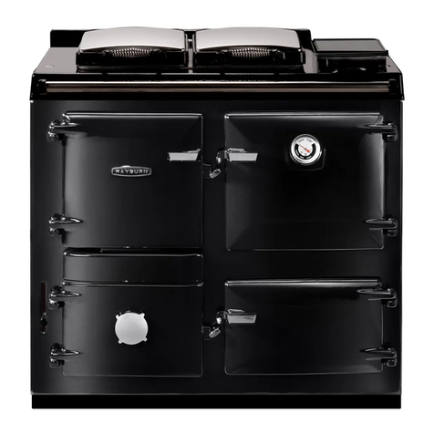
Rayburn supreme User manual

1
R
R
A
AY
YB
BU
UR
RN
N
S
S
U
UP
PR
RE
EM
ME
E
/
/N
N
O
OU
UV
VE
EL
LL
LE
E
/
/3
35
55
5
S
S
U
U
S
SE
ER
R
I
I
N
NS
ST
TR
RU
UC
CT
TI
IO
ON
NS
S
I
I
S
SS
SU
UE
E
4
4
http://www.oilsto es.co.uk/
Water
Temperature
Control Stat.

2
Contents
1. Introduction. ______________________________________________________________ 1
2. How Does it Operate?_______________________________________________________ 1
3. Description of Controls. _____________________________________________________ 1
Time Clock or On Off Switch. _________________________________________________ 1
Water Temperature Sensing Thermostat. _________________________________________ 1
Stat drive information ________________________________________________________ 1
Oven Temperature Control ____________________________________________________ 2
Lever Operated Boiler - Cooker DAMPER. ______________________________________ 2
4.The New Baffle System.______________________________________________________ 2
Winter Time Running. _______________________________________________________ 2
Summer Time Running. ______________________________________________________ 2
Isolated Cooking or Heating. __________________________________________________ 2
5.The Central Heating Pump. __________________________________________________ 3
6.Main Burner Control Unit.___________________________________________________ 3
7. Using The Con erted Appliance.______________________________________________ 3
Warning. __________________________________________________________________ 3
The Boiler / Cooking Damper. _________________________________________________ 3
Heating Position.____________________________________________________________ 3
Cooking Position. ___________________________________________________________ 3
8. Typical Run Situation. ______________________________________________________ 3
To Increase The Oven Temperature. ____________________________________________ 4
To Decrease The Oven Temperature.____________________________________________ 4
9. Running Costs. ____________________________________________________________ 4
10. P
recautions. _____________________________________________________________ 4
The Control Box Lockout Button. ______________________________________________ 4
The Electrical Isolation Point. _________________________________________________ 4
The Oil Supply Valves and Filter. ______________________________________________ 4
The Fire Valve. _____________________________________________________________ 4
Warning. __________________________________________________________________ 4
11. Ser icing. ________________________________________________________________ 5
Frequency. ________________________________________________________________ 5
Air for Combustion. _________________________________________________________ 5
Warranty Registration. _______________________________________________________ 5
Calibrate Fuel Tank Gauge. ___________________________________________________ 5
Fuel Re Order. _____________________________________________________________ 5
Fuel Type. _________________________________________________________________ 5
12. In The E ent of a Stoppage._________________________________________________ 5
Control Lock Out ___________________________________________________________ 5
Empty Fuel Tank. ___________________________________________________________ 5
Activated Safety Controls. ____________________________________________________ 5
Time clock. ________________________________________________________________ 5
Thermostatats.______________________________________________________________ 5
Electrical Fuses. ____________________________________________________________ 5

1
1
1.
.
I
I
N
NT
TR
RO
OD
DU
UC
CT
TI
IO
ON
N
.
.
The Rayburn Supreme and Nouvelle cookers are
ideally suited for conversion.
They have an excellent hot plate and a good cast
iron lined upper oven.
They are robustly constructed and renown for the
quality of vitreous enamel applied to the exterior
castings.
The conversion system fitted to your Rayburn
will enhance and compliment its many attractive
features as well as bring the advantages of
clean automatic heating to your home.
It can provide a maximum output to water of up
to 55 000 BTUs via an automatic pressure jet oil
burner firing vertically through a simple patented
baffle system.
It is-:
Simple and easy to use.
Easy to maintain.
Easy to ser ice.
2
2.
.
H
H
O
OW
W
D
D
O
OE
ES
S
I
IT
T
O
O
P
PE
ER
RA
AT
TE
E
?
?
Providing the appliance has been converted
correctly and in line with our installation
instructions
the cooker will operate in much
the same way as a solid fuel cooker with 3
major differences.
1. You can rapidly turn it on and off whenever
you require.
2. You will get a constant heat output instead of
a fluctuating one.
3. You will be able to hold a steady oven
temperature automatically via the water
temperature control thermostat.
You will not be able to operate the o en
independently from the boiler as the two are
interlinked in the original design of the
cooker.
Here is a description of how your converted
appliance works
Imagine instead of coal fire in the firebox a
large flame generated by the burner which
can be diverted
a) Around the boiler and
through an extra
part of the boiler,
b) Around a part of the boiler and then o er
the o en.
Obviously if you divert the flame around
and through the boiler more of the heat from
the flame will go into the water and the
resultant flue gases will be cooler.
If you divert the flame across the oven top
the resultant flue gases will be much hotter
and will then put the extra heat into the oven.
In each case the hot plate will get hot.
3
3.
.
D
D
E
ES
SC
CR
RI
IP
PT
TI
IO
ON
N
O
OF
F
C
C
O
ON
NT
TR
RO
OL
LS
S
.
.
Controls which will affect the performance of
the appliance and which you should be familiar
with are as follows-:
T
T
I
IM
ME
E
C
C
L
LO
OC
CK
K
O
OR
R
O
O
N
N
O
O
F
FF
F
S
S
W
WI
IT
TC
CH
H
.
.
Your Installer will inform you of how the
appliance will be activated.
W
W
A
AT
TE
ER
R
T
T
E
EM
MP
PE
ER
RA
AT
TU
UR
RE
E
S
S
E
EN
NS
SI
IN
NG
G
T
T
H
HE
ER
RM
MO
OS
ST
TA
AT
T
.
.
S
S
T
TA
AT
T
D
DR
RI
IV
VE
E
I
IN
NF
FO
OR
RM
MA
AT
TI
IO
ON
N
There are two different situations which can
effect the positioning of this device.
1. Situations where the appliance has been
correctly installed.
There will be enough space at the left hand side
of the appliance for the conversion engineer to
gain access to the original water temperature
control thermostat.
Original stat
Drive knob

2
This will mean that you will be able to use the
existing drive knob on the top left hand side of
the enamelled hob.
There is a slight discrepancy between the
original scale of 1 to 8 and that of the new
thermostat which is 1 to 6.
There is also a further slight problem in as much
as the original drive to the stat is a flexible shaft
which does not give a positive action.
To overcome this you will need to use a certain
amount of trial and error to establish familiarity
with the stat drive and corresponding numbers
with experience you will learn where to set the
drive knob to suit your particular requirements.
2. Situations where the appliance has not been
correctly installed.
There may not be enough space at the left hand
side of the appliance to gain access to the
original stat.
In these situations there are two possibilities
1. A separate stat holder box situated near to or
on the appliance.
2. A pair of clip on pipe stats situated in a
convenient position near to the appliance.
The installer may well need to discuss the best
possible option of fitting a temperature control
stat if it can’t be fitted in it’s original position.
The control of either stat should be-:
Rotate the control knob clockwise or anti
clockwise to either increase or decrease the
water temperature.
(This device automatically controls the water
temperature and also has a direct effect on the
idling temperature of both the oven and the hot
plate, i.e. the hotter the water temperature
required the hotter both the oven and the
hotplate will become)
L
L
E
EV
VE
ER
R
O
O
P
PE
ER
RA
AT
TE
ED
D
,
,
B
B
O
OI
IL
LE
ER
R
-
-
C
C
O
OO
OK
KE
ER
R
D
DA
AM
MP
PE
ER
R.
.
(The Chrome lever situated in the centre of the
appliance just below the hob.)
This device allows the user to bias heat to either
the oven or the boiler.
The original design of the appliance will not
allow the user to run the heating or cooking
separately.
4
4.
.T
T
H
HE
E
N
N
E
EW
W
B
B
A
AF
FF
FL
LE
E
S
S
Y
YS
ST
TE
EM
M
.
.
Fitted inside the appliance this item is altered
from SUMMER to WINTER positions by the
service engineer.
It consists of a circular tube with a ceramic board
lid.
In the sides of the tube are two rectangular holes
which are designed to shoot the flame in the
required direction.
W
W
I
IN
NT
TE
ER
R
T
T
I
IM
ME
E
R
R
U
UN
NN
NI
IN
NG
G
.
.
During the WINTER TIME this direction is to
the rear and left hand side of the appliance
directly opposite the metal faces of the boiler.
The logic is that because the burner will be
running for longer periods of time, there will be
enough heat to eep the oven at a reasonable
temperature without having flames directed at it.
S
S
U
UM
MM
ME
ER
R
T
T
I
IM
ME
E
R
R
U
UN
NN
NI
IN
NG
G
.
.
During the SUMMER to the right (oven) and
front of the appliance.
The logic here is because there is less need to
heat the water; the majority of heat should be
directed at the oven.
If required the holes can be positioned anywhere
in between.
Note
This process of baffle adjustment is called
HEAT BALANCING.
In general solid fuel cookers are fitted in a wide
variety of different applications with differing
heat loads applied to them because of this there
will be a need for some sort of adjustment to get
the right HEAT BALANCE established for each
different installation.
I
I
S
SO
OL
LA
AT
TE
ED
D
C
C
O
OO
OK
KI
IN
NG
G
O
OR
R
H
H
E
EA
AT
TI
IN
NG
G
.
.
It is not possible to completely isolate either the
oven or the boiler from the heat generated by the
burner.
O
O
V
VE
EN
N
T
T
E
EM
MP
PE
ER
RA
AT
TU
UR
RE
E
C
C
O
ON
NT
TR
RO
OL
L
The oven temperature control is an optional
extra.

3
It is mounted on the left hand side panel close to
the top of the appliance.
It is an additional thermostat calibrated at oven
temperatures 50 to 300 C which is simply wired
in series with the water temperature control stat.
The use of this control is limited because it is not
possible to separate the oven from the boiler.
To set it turn the water stat up to maximum and
set the oven stat at the desired temperature when
the desired temperature is reached the oven stat
will turn the burner off as the oven cools down
the burner will fire up occasionally to maintain
the oven temperature.
If the water temperature is already high when
you want to increase the o en temperature the
water stat may well cut the burner off
regardless of the temperature setting.
Remember that if the water is up to temperature
and the burner is allowed to carry on running
then the system would boil and obviously this
will not happen because the water temperature
control stat will stop it.
5
5.
.T
T
H
HE
E
C
C
E
EN
NT
TR
RA
AL
L
H
H
E
EA
AT
TI
IN
NG
G
P
P
U
UM
MP
P
.
.
Can be turned on and of by a switch or
automatically by a time clock.
6
6.
.M
M
A
AI
IN
N
B
B
U
UR
RN
NE
ER
R
C
C
O
ON
NT
TR
RO
OL
L
U
U
N
NI
IT
T
.
.
The main burner control unit (control box) auto-
matically controls and times all the functions of
the burner and normally you will not need to
know too much about it other than how it fits in
the general pattern of the control system which
is as follows: -
Power is supplied from either a manual or timed
on - off switch to the thermostat and then to the
controller.
The controller looks after the burner and makes
sure everything happens in the correct order.
The only time you will notice the controller is if
the burner fails to ignite.
In this case it will (GO TO LOCK OUT) and the
orange reset button will illuminate indicating a
problem has occurred during the ignition
sequence.
Before you can attempt to relight the burner you
will have to wait for about three minutes before
you can press the button to extinguish the light
and let the controller try to re-ignite the burner.
If lockout occurs after a reset you must call out a
service engineer to investigate the cause.
7
7.
.
U
U
S
SI
IN
NG
G
T
T
H
HE
E
C
C
O
ON
NV
VE
ER
RT
TE
ED
D
A
A
P
PP
PL
LI
IA
AN
NC
CE
E
.
.
W
W
A
AR
RN
NI
IN
NG
G
.
.
Always use a heat resistant glo e when using
the chrome boiler
/
cooking le er as it will get
hot during normal running.
With a little experience you will soon learn what
oven temperature to expect in relation to water
temperatures and although normally to increase
the oven temperature you will have to open the
boiler / cooking damper to it's cooking position
this may not always be the case.
T
T
H
HE
E
B
B
O
OI
IL
LE
ER
R
/
/
C
C
O
OO
OK
KI
IN
NG
G
D
D
A
AM
MP
PE
ER
R
.
.
Is operated by a chrome lever located in the
centre of the appliance just beneath the hob
return.
It provides the means to direct the flame from
the burner either around the boiler / hotplate and
through the rear boiler flue ways for high
efficiency heating or around the first part of the
boiler the hot plate and then the oven for more
of your oven and cooking needs.
H
H
E
EA
AT
TI
IN
NG
G
P
P
O
OS
SI
IT
TI
IO
ON
N
.
.
When the chrome lever is in a vertical position it
is in the heating position.
C
C
O
OO
OK
KI
IN
NG
G
P
P
O
OS
SI
IT
TI
IO
ON
N
.
.
When the chrome lever is lifted into a horizontal
position it is in the cooking position.
It is not possible to completely isolate the boiler from
the flame, but it is possible to swing the majority of
the heat either into the water or into a hot plane and
oven, if you wish to run the coo er during the
summertime for coo ing you will need to purchase
the summertime boiler insulation bric s.
You will very quickly learn to use the converted
appliance but to give you a start we illustrate a
typical situation-:
8
8.
.
T
T
Y
YP
PI
IC
CA
AL
L
R
R
U
UN
N
S
S
I
IT
TU
UA
AT
TI
IO
ON
N
.
.
The cooker is in its water heating state with the
lids down the boiler /cooking damper lever is in
boiler position and the water stat set to give a
water temperature of 60 deg C the cooker has
This manual suits for next models
2
Table of contents
Other Rayburn Kitchen Appliance manuals

Rayburn
Rayburn 300W User manual

Rayburn
Rayburn Heatranger 216SFW User manual

Rayburn
Rayburn 680KCD C User manual

Rayburn
Rayburn Heatranger 345W User manual

Rayburn
Rayburn 370 SFW User manual

Rayburn
Rayburn Cookmaster 300K User manual

Rayburn
Rayburn 660 User manual

Rayburn
Rayburn Heatranger 355SFW User manual

Rayburn
Rayburn Two-Oven Operating manual

Rayburn
Rayburn Heatranger 880 Installation instructions