RaySafe Solo User manual

USER MANUAL
RaySafe Solo

© 2018.10 Unfors RaySafe 5001053-4.00
All rights are reserved. Reproduction or transmission in whole or in part, in any form or by any means,
electronic, mechanical or otherwise, is prohibited without the prior written consent of the copyright owner.
2

CONTENTS
INTRODUCTION .................................................................................................... 5
Versions........................................................................................................... 5
About this user manual................................................................................... 5
THE RAYSAFE SOLO.............................................................................................. 6
The RaySafe Solo detector options................................................................ 6
Easy to use.......................................................................................................7
GETTING STARTED.................................................................................................8
Keys on the RaySafe Solo base unit................................................................8
Battery and Charger ....................................................................................... 9
R/F MEASUREMENT .............................................................................................10
MAMMOGRAPHY MEASUREMENT....................................................................... 13
CT MEASUREMENT .............................................................................................. 16
How to measure CT dose.............................................................................. 16
LIGHT MEASUREMENT......................................................................................... 19
mA/mAs MEASUREMENT .................................................................................... 22
Passive mAs .................................................................................................. 25
MEASUREMENT DEFINITIONS ............................................................................ 26
Dose .............................................................................................................. 26
Dose Rate...................................................................................................... 28
kV/kVp ........................................................................................................... 28
Time............................................................................................................... 29
Pulse.............................................................................................................. 30
HVL (Half Value Layer) – optional ................................................................ 30
Total Filtration – optional............................................................................... 31
mA and mAs................................................................................................... 31
RAYSAFE SOLO PC KIT........................................................................................ 32
RaySafe Xi View............................................................................................ 32
Transfer data to a computer......................................................................... 33
Installing RaySafe Xi View ............................................................................ 33
3
RaySafe Solo User Manual – Contents

Setup of Bluetooth communication.............................................................. 33
Getting help ...................................................................................................34
ACCESSORIES ..................................................................................................... 35
The RaySafe flexi stand ................................................................................ 35
The RaySafe OPG holder.............................................................................. 35
The RaySafe Cassette holder....................................................................... 36
TIPS AND TRICKS.................................................................................................37
Arrangement of Measurement......................................................................37
Vertical Detector Placement......................................................................... 38
kVp on AMX................................................................................................... 38
Display Codes ............................................................................................... 38
Frequently Asked Questions ........................................................................ 39
Troubleshooting............................................................................................. 41
WARRANTY, SERVICE AND SUPPORT..................................................................43
Service ...........................................................................................................43
Return Procedure for Service and Warranty .................................................43
DISPOSAL.............................................................................................................44
4
RaySafe Solo User Manual – Contents
INTRODUCTION
VERSIONS
This user manual covers the following articles:
base unit version: 8221011 detector version: 8222015
8221022 8222016
8222017
8222018
8222019
8222020
8222021
8222022
ABOUT THIS USER MANUAL
This user manual is intended to assist users in the safe and eective operation of the product described.
Before attempting to operate the product, you must read these instructions for use, noting and strictly
observing all WARNINGS and CAUTION notices.
WARNING A WARNING alerts you to a potential serious outcome, adverse event or safety hazard. Failure
to observe a warning may result in death or serious injury to the operator or patient.
CAUTION A CAUTION alerts you to where special care is necessary for the safe and eective use of
the product. Failure to observe a caution may result in minor or moderate personal injury or
damage to the product or other property, and possibly in a remote risk of more serious injury,
and/or cause environmental pollution.
NOTE Notes highlight unusual points as an aid to an operator.
These Instructions for Use describe the most extensive configuration of the product, with the maximum number
of options and accessories. Not every function described may be available on your product.
5
RaySafe Solo User Manual – Introduction

THE RAYSAFE SOLO
The RaySafe Solo is intended for measurements in medical X-ray imaging applications. The RaySafe Solo is not
intended for use during patient examination.
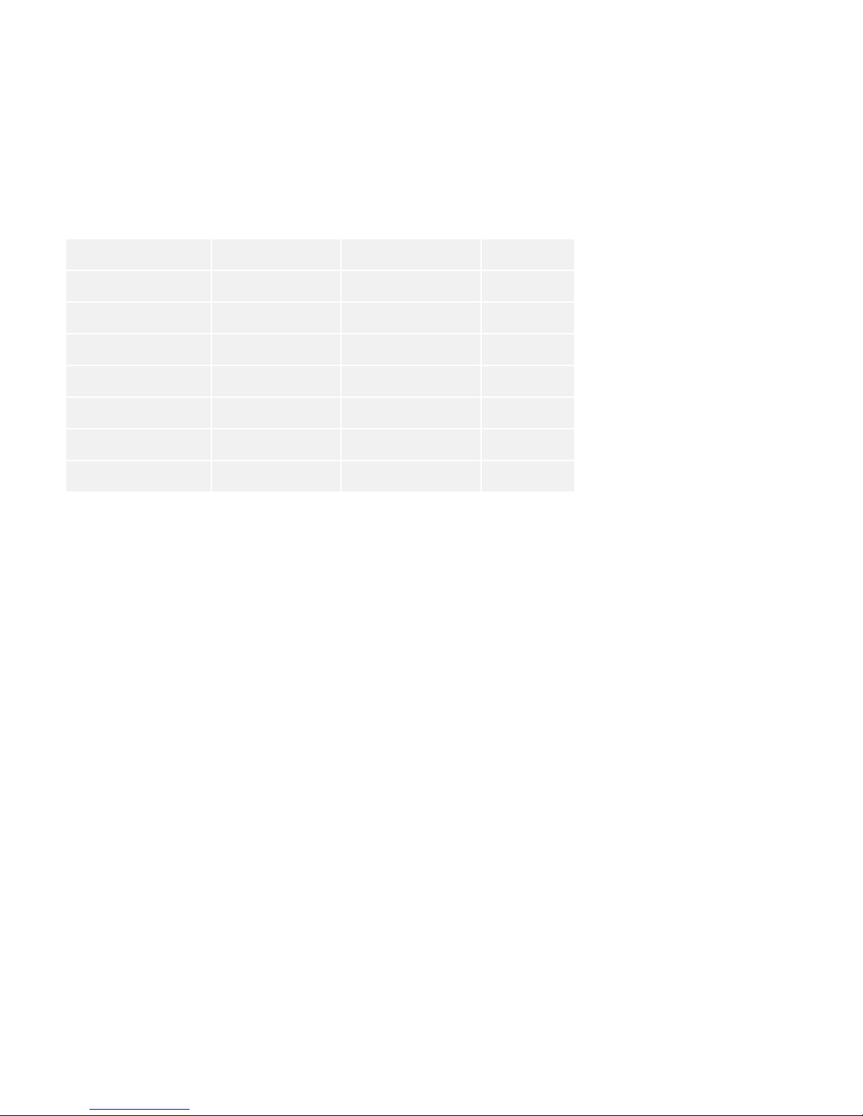
The RaySafe Solo consists of a base unit and a detector.
Communication between detector and base unit is purely digital, thereby minimizing sensitivity to mechanical
or electrical stress.
THE RAYSAFE SOLO DETECTOR OPTIONS
• The R/F detector has two sensors: R/F high is designed for conventional, high dose rate measurements.
R/F low is designed for low dose rate measurements. The RaySafe Solo R/F base unit can be equipped with
mA/mAs capabilities.
• The MAM detector is used for both low and high dose rates generated in mammography applications.
• The MAM dose detector is a Solo MAM detector, but measures only dose, dose rate and time.
• The Dose detector is an R/F detector, but measures only dose, dose rate, time and pulses.
• The RAD detector is designed for conventional, high dose rate measurements normally generated without a
phantom between the detector and the X-ray source.
• The CT detector is an ionization chamber, designed to measure CT dose for applications such as Dose
Length Product (DLP) and Computed Tomography Dose Index (CTDI).
• The DENT detector is designed for measurements on intraoral dental X-ray machines, OPG and Cone beam.
• The light detector is designed to measure luminance on LCD and CRT monitors, as well as light boxes, and
illuminance for diagnostic X-ray applications.
• There is also a RaySafe Solo mAs model for measuring mA/mAs, time and pulses.
6
RaySafe Solo User Manual – The RaySafe Solo
EASY TO USE
The RaySafe Solo is very easy to use.
The built-in active compensation automatically applies corrections for dierent beam qualities, filtrations and
temperatures. During fluoroscopy measurements the displayed values are continuously updated.
If your instrument is equipped with the RaySafe Solo PC kit, data is sent on the serial port to your computer,
where RaySafe Xi View shows numerical data as well as waveforms.
7
RaySafe Solo User Manual – The RaySafe Solo

GETTING STARTED
1. Connect the detector to the base unit with one of the two (2 and 10m) cables.
2. Position as required for the detector, see the following chapters.
3. Turn on the RaySafe Solo (ON/OFF key, see below), and the instrument specific setup information is
displayed. In the SENSOR MENU a detector or sensor field for your application can be selected.
4. The instrument is now in MEASURE MODE and ready to measure. Press STEP to scroll through measured
parameters (also possible during fluoroscopy). The last three displayed parameters will automatically show
up after the next exposure. To change setup values (SETUP MENU) such as various delays, displayed units
and other choices, press SELECT.
KEYS ON THE RAYSAFE SOLO BASE UNIT
ON/OFF: Turns on the RaySafe Solo and o when in SENSOR MENU.
EXIT: Exit to the previous menu.
STEP: A short press steps through available options.
SELECT: A long press selects an option.
8
RaySafe Solo User Manual – Getting Started

BATTERY AND CHARGER
The RaySafe Solo base unit has a chargeable 7.4 V Li-ion battery, providing approximately 20 – 40 hours of
operation (depending on selected detector and whether Bluetooth is used). Since chargeable batteries have a
self discharge current, RaySafe strongly recommends fully charging the battery before first use. Battery level is
displayed, together with setup information, when the instrument is switched on.
There are two battery warning levels:
• First warning level, “Battery low”: Finish your measurements and then charge the battery.
• Second warning level, “Battery down”: No further measurements are recommended.
The provided battery charger may be connected during measurement. When connected, the external power
indicator is lit and Charging battery will be briefly displayed.
The battery will be charged even if the instrument is turned o. The charge time from empty to full is
approximately 4 hours.
9
RaySafe Solo User Manual – Getting Started
R/F MEASUREMENT
Using R/F, RAD, Dose or DENT version.
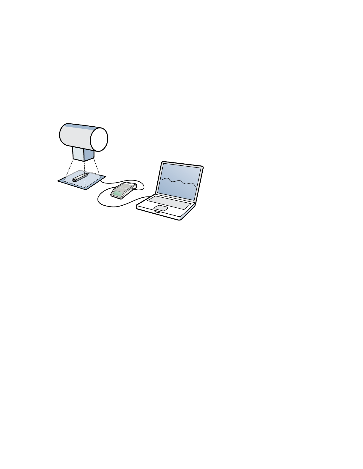
For best accuracy, center the selected sensor field (R/F low, R/F high, RAD, DENT low or DENT high) and
position the long axis of the sensor field perpendicular to the anode-cathode axis of the tube.
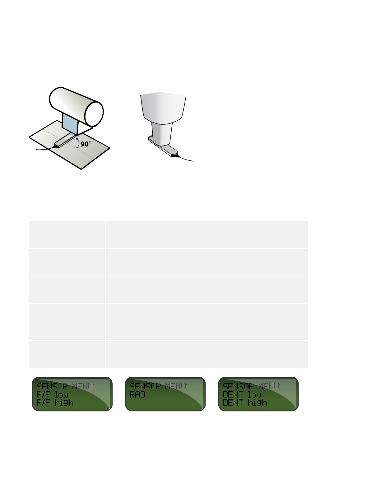
1. SENSOR MENU
R/F low
(R/F and Dose)
Sensor for conventional low dose rate measurements < 1 mGy/s
(7 R/min), normally after a phantom.
R/F high
(R/F and Dose)
Sensor for conventional high dose rate measurements > 1 mGy/s
(7 R/min), normally before a phantom.
RAD Sensor for conventional high dose rate measurements > 0.1 mGy/s
(0.7 R/min), normally before a phantom.
DENT low Sensor for low dose rate measurements < 1 mGy/s
(7 R/min), normally after a phantom or for applications with high
(> 10 mm Al or equivalent) inherent filtration.
DENT high Sensor for high dose rate measurements > 1 mGy/s
(7 R/min), normally before a phantom.
Press STEP to step between sensors and SELECT to select a sensor.
10
RaySafe Solo User Manual – R/F Measurement
Table of contents


