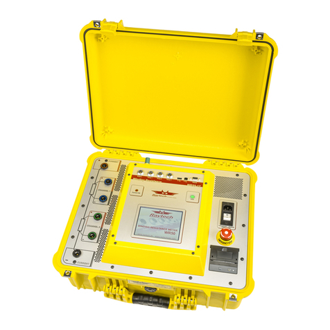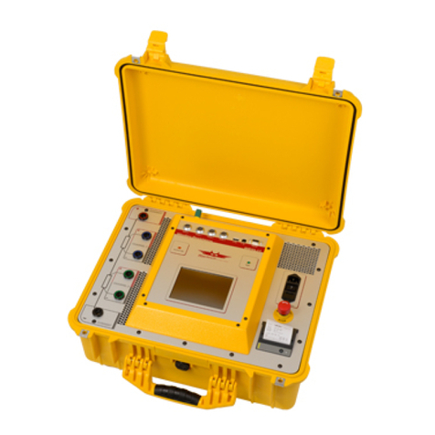
WR14 / WR50-12/13 Winding Resistance Meter Instruction Manual
TABLE OF CONTENTS
Safety Precautions........................................................................................................................................5
Unpacking .....................................................................................................................................................6
WR50.........................................................................................................................................................6
WR14.........................................................................................................................................................7
Introduction....................................................................................................................................................8
General......................................................................................................................................................8
Advantages & Features.............................................................................................................................9
System Details...........................................................................................................................................9
System Check........................................................................................................................................9
Limitations of Winding Resistance Testing............................................................................................9
Discharging the Transformer Windings ...............................................................................................10
Low Resistance Testing.......................................................................................................................10
Quick Start Guide........................................................................................................................................11
Instrument Operation –Profiles Deactivated...........................................................................................11
Instrument Operation –Using Profiles ....................................................................................................12
Selection of the Proper Current Range ...................................................................................................14
Connection to the Test Object.................................................................................................................14
Single Phase Transformer, Vector Group 0.........................................................................................15
Three Phase Transformer, Δ–ΔVector Group 0 ...............................................................................16
Three Phase Transformer Δ–Y, One LV Winding .............................................................................17
Three Phase Transformer Δ–Y, Two LV Winding .............................................................................18
Operation Elements for field units...............................................................................................................19
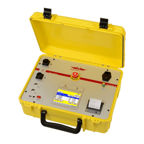
WR50 Front Panel Overview:.................................................................................................................19
WR50 Control Elements and Connections..............................................................................................19
Fuse, Mains Input and Switch..............................................................................................................19
Emergency Stop ..................................................................................................................................19
Thermal Printer ....................................................................................................................................19
Safety Indicator....................................................................................................................................20
Display With Touch Panel....................................................................................................................20
Potential Receptacle............................................................................................................................20
Current Receptacle..............................................................................................................................20
External................................................................................................................................................20
Ground Terminal..................................................................................................................................20
Temperature Receptacle .....................................................................................................................20
Interface...............................................................................................................................................20
WR14 Front Panel overview....................................................................................................................21
