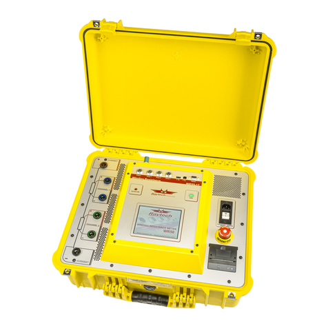
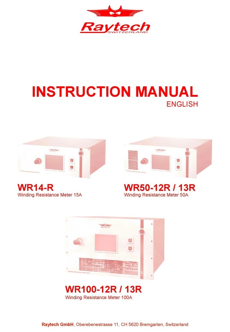
Raytech WR50-12 User manual

RAYTECH USA, Inc.
90C Randall Avenue
Woodlyn, PA 19094 USA
Tel. 888 4 THE SPY
Tel. 610 833 3016
Fax. 610 833 3018
50 Amp / 2 Channel Winding Resistance Meter
Model: WR50-12
Preliminary Instruction Manual Ver. 1.03

Raytech USA, Inc. All rights reserved. No portion may be reproduced without written consent. 2
RAYTECH USA, Inc.
T A B L E O F C O N T E N T S
Section Page(s)
Table of Contents – 2
Safety Precautions 1 – 0 3
Uncrating Procedure 2 – 0 4
Technical Specifications 3 – 0 5
Introduction 4 – 0 6
Advantages & Features 6
System Details 5 – 0 7
Limitations of Testing 7
Discharging Transformer Windings 7
Demagnitization 7
Front Panel Description 6 – 0 8
Power, USB Ports, Serial Port, Safety Switch 8
Printer, Temperature inputs, External, Warning lights 9
Test connection inputs, ground terminal, vents 10
Operation 7 – 0 11
Getting started 7 – 1 11
Adjusting the Test Current 12
During measurement, Demagnitization feature 13
Changing test mode; Single, Cont., Interval 14
Archive / Stored Results 7 – 2 15
General Menu 8 – 0 16
Service Mode, About 17
Update Firmware 18
Setting the Clock, Length Correction 19
Temperature measurements (Option TP 01) 9 – 0 20
Temperature Correction 9 – 1 20,21
Basic Instructions 10 – 0 22
Quick Test 10 – 1 22
Trouble Shooting 11 – 0 23
Error Messages 12 – 0 24
Warranty 13 – 0 25

Raytech USA, Inc. All rights reserved. No portion may be reproduced without written consent. 3
SAFETY PRECAUTIONS! 1 – 0
The following safety precautions must be observed during all phases of operation, service, and
repair of this instrument. By purchasing this equipment the purchaser assumes all liability for
the operation and use of this equipment. The intended use of the instrument, its design and
manufacture, is to be conducted within the precautions or other specific warnings located
within this manual. Failure to comply with these precautions and other specific warnings
violates safety standards of design, manufacture, and intended use. Raytech Switzerland
assumes no liability for the operation and use of this equipment.
SAFE OPERATION
Only qualified knowledgeable persons should be permitted or attempt to operate this test
equipment. All test personnel should fully familiarize themselves with the correct application
and operation of this and all test equipment prior to operation. Persons directly and indirectly
engaged in the operation of this test equipment should keep clear of all high voltage apparatus
while conducting tests and measurements.
BEFORE APPLYING POWER
Read this manual carefully before operating the system. The WR50-12 is line operated. The
system operates from a wide range power input from 100 to 250 Vac 50/60Hz.
DO NOT OPERATE IN AN EXPLOSIVE ATMOSPHERE
Do not operate the instrument in the presence of flammable gases or fumes.
KEEP AWAY FROM LIVE CIRCUITS
Operating personnel must not remove instrument covers. Component replacement and internal
repairs must be made by qualified service personnel. Do not replace components with power
cable connected. To avoid injuries, always disconnect power, discharge circuits, and remove
external voltage sources before touching components.
DO NOT SUBSTITUTE PARTS OR MODIFY INSTRUMENT
Because of the danger of introducing additional hazards, do not install substitute parts or
perform any unauthorized modification to the instrument. Return the instrument to the Raytech
USA service department for service to ensure proper operation and that safety features are
maintained.
Instruments which appear damaged or defective should be made inoperative and secured
against unintended operation until they can be repaired by qualified service personnel.
TEST WARNING
* DO NOT USE ON LIVE CIRCUITS *

Raytech USA, Inc. All rights reserved. No portion may be reproduced without written consent. 4
UNCRATING PROCEDURE: 2 – 0
Unpack your new WR50-12 and check to see that you have the following standard items:
WR50-12 Potential Current Safety
Leads Leads Ground
Cable Carry Case Jumper Instruction Power Stylus External
with shoulder strap Lead Manual Cord USB drive
If any of the above items are missing or damaged contact your local representative or Raytech
USA immediately.
Custom test lead sets, other than shown, may be purchased with the WR50-12.
* Note:
The WR50-12 Field case is a waterproof design that incorporates an automatic pressure relief
valve that will adjust to various atmospheric changes; i.e... Airplane Travel, High altitudes,
etc... The valve is designed to be water resistant.

Raytech USA, Inc. All rights reserved. No portion may be reproduced without written consent. 5
TECHNICAL SPECIFICATIONS 3 – 0
MODEL: WR50-12
SIZE: L: 521 mm (20.5”) W: 432 mm (17”) H: 216 mm (8.5”)
WEIGHT: 18.8 kg (41.5 lbs.)
INPUT POWER: 100 to 250 Vac (1.5kW max.), 50/60 Hz, Automatic ranging
OUTPUT VOLTAGE: 0 to 50V DC
TEST CURRENT: User Selectable: 50…. 0.1 Ampere
PANEL DISPLAY: Color LCD with back lighting and touch screen
FRONT PANEL: Sealed anodized
INTERFACE: 9 Pin RS232 Serial / 2 USB 1.1 Type A and B
MEMORY STORAGE: Stores up to 10000 complete test results
RESISTANCE RANGE: 0.00 µΩ to 100.0 kΩ
INDUCTANCE RANGE: 0 Henry to 1500 Henry
MEASUREMENT PARAMETERS:
Current Range Measuring Range Accuracy Resolution
50 – 30 A 0.00 µΩ…....1.6 Ω±0.1% Rdg ±0.05 µΩ 5 Digits or 0.05 µΩ
30 – 15 A 0.0 µΩ…......3.3 Ω±0.1% Rdg ±0.1 µΩ 5 Digits or 0.1 µΩ
15 – 8 A 0.0000 µΩ…6.3 Ω±0.1% Rdg ±0.2 µΩ 5 Digits or 0.2 µΩ
8 – 3 A 0.0000 µΩ..16.7 Ω±0.1% Rdg ±0.5 µΩ 5 Digits or 0.5 µΩ
3 – 1 A 0.000 µΩ…47.2 Ω±0.1% Rdg ±1 µΩ 5 Digits or 1 µΩ
1 – 0.7 A 0.000 µΩ….71.4 Ω±0.1% Rdg ±2 µΩ 5 Digits or 2 µΩ
0.7 – 0.3 A 0.000 µΩ…..167 Ω±0.1% Rdg ±5 µΩ 5 Digits or 5 µΩ
0.3A – 0.1 A 0.00 µΩ……500 Ω±0.1% Rdg ±10 µΩ 5 Digits or 10 µΩ
100 mA – 25 mA 0.00 µΩ…......2 kΩ±0.1% Rdg ±20 µΩ 5 Digits or 20 µΩ
– 25 mA 2 kΩ…..........10 kΩ±0.1% Rdg ±200 µΩ 5 Digits or 200 µΩ
– 25 mA 10 kΩ….......100 kΩ±0.8% Rdg ±20 Ω5 Digits or 20 Ω
TEMPERATURE : Operating: -10°C to 60°C Storage: -20°C to 70°C
CABLE SET / ACCESSORIES
Current & Potential lead set (10 meters), Jumper lead (10 Meters), Safety ground lead (10 meters),
power cord, Instruction Manual, Stylus, extra paper, external USB drive and cable set carry case.
FEATURES: Standard Items
Charges inductive loads up to 1500 Henry
Heavy duty protection circuitry
Simple touch screen operation
Data exchange with an USB-Key
3 Temperature channels
High power DC Supply ( 50A/50V )
DC Current adjustable for resistance values from 0.0 µΩ to 100 kΩ
Fastest Discharge unit on market ( more then 10 times faster )
Discharge Indicator – visible and audible indicator for discharge status
Demagnetizing Circuit
Warning Lamp to show “Transformer under test”
Emergency stop push button immediately turns off power and starts discharging
Data transfer to internal Printer
Data Storage of up to 10000 measurements
Mounted in rugged case for field testing.
5 Year standard warranty
OPTIONS:
Part No - TP01: External temperature probe
Part No - AHRT 01: Heat Run Test
* Specifications are subject to change at anytime.
Raytech USA, Inc. All rights reserved. No portion may be reproduced without written consent. 6
INTRODUCTION 4 – 0
Raytech Digital Winding Resistance meter, WR50-12, was designed for high degree of
accuracy for the measurement of very low resistance of inductive loads. This technology was
then packed into a portable test system for use by apparatus manufacturers, rebuild shops, and
electrical maintenance crews.
Ease of use: This intelligent system has an easy to use operation screen, which allows quick
selection of the current level to be measured. Use the Touchscreen to change or activate an
item.
Impressive Accuracy: The WR50-12 is a high precision, fully automatic, multi-microprocessor
based system. This system is designed for highly accurate readings on-site with laboratory
precision.
Unique Measuring Technique: This newly designed technique of measurement incorporates a
high precision measurement circuit ,a unique power source and the fastest discharge unit on
market. Extensive filtering and high precision standards are used within the test system. The
system is capable of precision measurements to 50 A.
Operation: The WR50-12 applies a preset current level, selected by the User. The 50V power
source quickly charges the load. The results of the test are then displayed within a few seconds
automatically. The results are reported on the easy to read color LC display and can be stored or
printed.
Compact Design: The WR50-12 is one of the most lightweight systems available that comes
complete with its own rugged waterproof Fieldcase.
Simple Maintenance: There is No maintenance required. This is due to the utilization of high
precision components in the design.
Advanced Protection: Upon powering on, the system initializes itself with a self-calibrating,
circuit checking sequence. If any problems are detected during this initialization period, or
during operation, the operator is immediately notified. The system constantly monitors the
condition when turned on. The WR50-12 has extensive protection built in to the circuitry. This
is one of the many reasons we can extend our warranty to 5 years.
Advantages & Features:
Highest accuracy and Precision of any high current test system
Automatic measurements of Low Resistance from 0.1µΩ ...100kΩ
Microprocessor based system with internal storage for over 10000 test results
Printing and Storage of test results while the test system is measuring
Complete automatic calibration system and system diagnostics
Standard USB 2.0 & RS232 (serial) Interface
Pure filtered DC Power source for the highest accuracy readings
Automatic, high efficiency cooling system to dissipate internal temperatures
Automatic shut off for over-temperature condition
Automatic Demagnetization circuit built-in
Panel mounted Emergency Stop Switch
Wide input power source range
Lightweight and Portable, less than 19 kg (42 Lbs.)
5 Year standard warranty

Raytech USA, Inc. All rights reserved. No portion may be reproduced without written consent. 7
SYSTEM DETAILS: 5 – 0
System Check:
The instrument is Line operated. The system is designed to be used with voltage power sources
(mains power) between 90-260 Vac 50/60Hz. The system performs a self check each time it is
powered on. The User should always visually inspect all connectors, cables and devices to be
measured to avoid any safety issues.
Limitations of Winding Resistance Testing:
In general,there are no limitations on testing low or high inductive windings of transformers.
The test system is specially designed to test all transformer windings.
Low Resistance Testing:
The WR50-12 utilizes the 4 wire measuring technique. The points where the potential leads are
connected determine the resistance reading. The test set employs a very simple principle of
Ohm’s law: R=V/IR= Resistance, V = Voltage, I= Current
Discharging Transformer Windings:
The WR50-12, as well as all of the WR50 series, are specialized systems designed to measure
transformer windings. These systems are equipped with heavy duty discharge circuits that are
very unique in the market!
The internal discharge circuit dissipates the stored energy in the transformer windings with
Constant Power Discharge Circuit which is unique to all transformer winding test systems.
That is the reason why Raytech systems can discharge transformers more then 10 times faster
then any other system on the market.
If a cable happens to fall off during test, the system will STILL discharge the test object safely
with the automatic Constant Power Discharge Circuit
The Potential Test Leads are part of the safety circuit and have the ability to discharge a
transformer in the case where a current lead may become detached.
DO NOT USE A SMALLER GAUGE POTENTIAL (VOLTAGE) CABLES THEN
ORIGINAL CABLES SUPPLIED!
Demagnetization:
Upon completion of a transformer winding resistance test the core material may become
magnetized due to the Direct Current that had been applied to the Windings. This magnetization
of the core must be removed prior to energizing the transformer for use.
The WR50-12 incorporates a demagnetization circuit which will automatically evaluate the
magnitude of the magnetization of the core and reduce it to a safe level. This process is
performed quickly and safely.

Raytech USA, Inc. All rights reserved. No portion may be reproduced without written consent. 8
FRONT PANEL DESCRIPTION: 6 – 0
Power Emergency OFF
Power cord connection Press to stop
On/Off switch Turn Clockwise to release
Accepts 100...250 Vac
50/60 Hz
Interfaces:
USB 2.0 Port: 1 Host and 1 Device
Serial Port: RS232 Bi-directional, Female 9 pin connector

Raytech USA, Inc. All rights reserved. No portion may be reproduced without written consent. 9
FRONT PANEL DESCRIPTION: (cont.) 6 – 0
Panel Mount Printer:
* The printer uses thermal heat transfer technology. Therefore, there are no ink cartridges
required or printer heads. Special thermal paper is required for printer to operate properly.
* This panel mount printer allows the user to print out stored results.
* The single button on the printer is for Form-Feed.
* To tear paper, pull paper towards the front of the instrument against the serrated cutting edge.
Temperature Probe connection: External Flashing light:
Three 2 pin Connections for optional Connection for an external Flashing
external temperature probes ( TP01 ) Light or Beeper to indicate a
Dangerous condition.
Working contact (230Vac 2A)
between Pin 3 + 4
Danger / Safe Condition Display:
Shows that Current is flowing. Shows that you bought Shows that test Object is
Do not remove any Cable! the right Instrument. in a Safe condition.

Raytech USA, Inc. All rights reserved. No portion may be reproduced without written consent. 10
Test Connections:
+Current = Positive Current connection
+Channel 1 = Positive Potential (voltage) connection of Channel 1
-Channel 1 = Negative Potential (voltage) connection of Channel 1
+Channel 2 = Positive Potential (voltage) connection of Channel 2
-Channel 2 = Negative Potential (voltage) connection of Channel 2
-Current = Negative Current connection
Ground Terminal
The ground connection is located towards the back panel of the raised portion of the faceplate.
It is spring loaded and threaded. Use the supplied ground wire to snap the spade under the
ground terminal. Do so by un-threading the green part. Or you may use a 4mm banana plug into
the top of this connector.
Vents
These vents pull in the air.
This is the exhaust vent.
*Please make sure there are no obstructions blocking these vents.
Damage to the system may occur.

Raytech USA, Inc. All rights reserved. No portion may be reproduced without written consent. 11
OPERATION: 7 – 0
WARNINGS!
BEFORE OPERATING THIS OR ANY OTHER TEST EQUIPMENT READ ALL SAFETY
WARNINGS AND UNDERSTAND THEM FULLY.
OPERATION:
This section describes a typical, step by step, operation of the WR50-12
Open the protection lid of the case and attach the test leads and the power cord to the test set.
The Two (2) connections on the front plate +Current & -Current are the current leads.
The Four (4) connections on the front plate +Channel 1 & -Channel 1 and +Channel 2 &
-Channel 2 are the Potential or Voltage leads.
By connecting a test specimen to the Current leads and applying the potential leads across the
specimen the resistance readings will be determined.
GETTING STARTED: 7 – 1
Turn on the Power switch, located at the power input connector, to the “I” position.
The Initial screen will appear. The Instrument will also make the initial calibration.
After a few seconds the main screen will appear:

Raytech USA, Inc. All rights reserved. No portion may be reproduced without written consent. 12
GETTING STARTED: (cont.) 7 – 1
The WR50-12 incorporates a touch-screen display for all input parameters. All Parameters are
initiated from the “Set up screen: General, Mode, Range, Temp. Corr., and Colors.
First, select the Current Range level to be used for the measurement by touching “Set up” and
then “Range”. The following screen (or similar) appears:
Select the Current level required by tapping on that range ( For example: 10A ). Immediately
after selection of the required current range, the system will revert to the test screen. Start the
measurement by just touching the “Start” Button. At the start of a test an single audible beep
will be heard as a reminder that the test system is about to charge the inductive windings.
Operators should be careful not to remove any cables while the test system is measuring.
* You may also customize the current output range by pressing “Set” on the bottom right hand
side of the screen. The following screen (or similar) appears:
Press the left or right arrows to adjust the current range.

Raytech USA, Inc. All rights reserved. No portion may be reproduced without written consent. 13
GETTING STARTED: (cont.) 7 – 1
During the measurement you will see the following (or similar):
The operator may press “Store “ at anytime to store a measurement. Multiple measurements can
be made while the instrument is running. These data will be stored as a complete record. The
current continues to flow and the system will measure until the Measurement is halted by
touching “Stop”.
DO NOT TOUCH, MOVE OR MANIPULATE THE MEASURING CABLES BEFORE YOU
HEAR TWO BEEPS AND THE DISPLAY AND LAMPS SHOW A SAFE CONDITION!
Demagnetization:
After completion of the winding resistance test, the operator may initiate the Automatic
Demagnetization Circuit. No removal or changing of the test leads are necessary or required.
The system is designed to operate the demagnetization circuit with the cables attached to the
transformer exactly as they were attached when performing the winding resistance test.
Simply press the “Demag” button on the test screen. Select the correct current and press start.
To select approproiate current, choose a current range above the test current. If testing at 30A,
select 40A, etc. The test system will then automatically detect the magnitude of stored energy
(if any) and demagnetize the transformer core.

Raytech USA, Inc. All rights reserved. No portion may be reproduced without written consent. 14
GETTING STARTED: (cont.) 7 – 1
Mode Tab:
This area includes the test settings, such as single, continuous, and interval. The Quality
Assistant is used for adjusting the instrument’s readings for when the current flow is
stable. You may select Auto Print Results if you desire to print the results after each
test.

Raytech USA, Inc. All rights reserved. No portion may be reproduced without written consent. 15
ARCHIVE: 7 – 2
To access the Archive (Memory locations), touch “Results”. The next screen will show the
stored records. Touch the Test record to select. Then touch “Details”.
The “Headers” column displays the listed stored results.
Saving multiple results during the measuring process stores the data under one header location.
All the stored results linked to a particular header are accessible by touching “Details”
By touching the arrows on the bottom left or right, you will see all the stored results of that
selected measurement. An empty field (ei.. T2) indicates that no temperature probe was plugged
into connector “Temp 2” on the front panel. The column “Time” is the time that has past after
starting the measurement process.
Selecting “Results” you get the following options:
ÕPrint selected Measurements
ÕPrint ALL the Measurements
ÕErase selected Measurement
ÕErase ALL Measurements
ÕStore the results to an USB-Device
(Removeable USB storage drive)

Raytech USA, Inc. All rights reserved. No portion may be reproduced without written consent. 16
GENERAL MENU 8 – 0
To access the Setup Menu, select (touch) “Setup” and then “General” . The above image is for
reference only and may differ from the actual display.
* License Manager
•Shows status of system license and allows user to add the heat run software code.
* Firmware Update
•To update or change the built in Firmware, see page 19.
* Language
•Allows user to select proper language; Deutsch, English, French, or Turkish.
* Clock Settings
•Setting the clock. See Page page 20.
* About
•Check the version of the installed Firmware. See page 18.
* USB Printer
•Allows user to assign an external printer to one of the USB Type A Ports.
* Service Mode
•Not for public use. See page 18.
* Length Correction
•For use when testing long lengths of cable.
* Alternative Caption
•Allows the user to change the name of Channel 1 or Channel 2 or Channel 3.
* Show Mouse Cursor
•Show or hide the Mouse Cursor. Usefull when using an external mouse via the USB
port.

Raytech USA, Inc. All rights reserved. No portion may be reproduced without written consent. 17
GENERAL MENU, cont. 8 – 0
SERVICE MODE
In the “Setup” Menu is a “Service Mode”. This Mode is for internal service use only and not
accessible. A login code is required. Touch “#” to Exit.
ABOUT
You can easily check the Firmware Version installed on your WR50-12, as well as the serial
number. In the general tab, touch “Setup” and then the “About” key .
*The above image is for reference only and may differ from the actual display.

Raytech USA, Inc. All rights reserved. No portion may be reproduced without written consent. 18
GENERAL MENU: (cont.) 8 – 0
UPDATE THE FIRMWARE
You can easily check the Firmware Version installed on your WR50-12. In the Main Display
touch “Setup”- and then the “About” key
A newer Version may be available and can be found at this link:
www.raytechusa.com
Download this new version and store it to the USB Key provided with the system.
Switch the WR50-12 on and plug the USB Key into the USB Port of the Instrument.
Select the Version you want to install and then press “Install” .
Please wait until the system reboots ro follow the on-screen instructions.

Raytech USA, Inc. All rights reserved. No portion may be reproduced without written consent. 19
GENERAL MENU, cont. 8 – 0
SETTING THE CLOCK
To set the clock go to the main screen and select (touch) the “Setup” and then the “Clock …”
Set the desired values by touching the Left, Right, or down arrows next to the related locations.
By selecting (Touching) “Set” the Clock will be activated and set.
*The above image is for reference only and may differ from the actual display.
LENGTH CORRECTION OPTION
This feature allows the user to set the length of cable that is under test. Along with the
“R” (resistance) correction for a particular length of cable.

Raytech USA, Inc. All rights reserved. No portion may be reproduced without written consent. 20
TEMPERATURE MEASUREMENTS 9 – 0
The system allows up to three (3) temperature probes to be used with the system for the purpose
of recording temperatures. Optional Part Number: TP 01, can be purchased for this purpose.
Recording the temperature of the device under test is highly recommended due to the
characteristics of the increase of resistance of a metallic object as its temperature increases.
There are temperature compensation tables for Copper and Aluminum available to calculate the
conversion factor to a known reference temperature.
The WR50-12 is a very accurate and precise test system. To take full advantage of this high
accuracy, the temperature of the device under test should be recorded.
The TP 01 temperature probe is mounted to a flexible extension cable that plugs into the front
panel of the WR50-12. This option enables the User to record the ambient temperature and/or
the actual temperature of the device under test.
The WR50-12 will automatically sense when the optional temperature probes, TP-01, are
connected to it. The temperature will be displayed on the instrument screen during a test and
will appear when a printed report is requested. The temperature, as well as the test results, can
be saved into memory.
TEMPERATURE CORRECTION 9 – 1
The WR50-12 can correct the measured values regarding the temperature.
To activate this feature, press “Setup” and then “Temp. Correction” .
In this example, the measured object is copper and will be corrected to 25 Degrees Celsius
based on the temperature on Temperature channel 1.
If you do not have a Raytech Temperature probe (TP-01), activate the “Ext” box and fill in the
temperature you measure with your other temperature probe or measuring device.
The correction follows the formula:
Rs = Rm[(Ts+Tk)/(Tm+Tk)] where
Rs is resistance at desired temperature, Ts
Rm is measured resistance
Ts is desired reference temperature
Tm is the temperature at which resistance was/is measured
Tk is 234.5 for copper, 225 for aluminum (aluminum may be as high as 240)
If you are used to a correction with “alpha25” you can calculate the Tk by the formula:
Tk=(1/alpha25)-25
If you are using another Tk then the standards for cooper or aluminum, activate the box
“User defined” and input the Tk in the box below.
Table of contents
Other Raytech Measuring Instrument manuals

Raytech
Raytech WR14-R User manual

Raytech
Raytech WR14 User manual

Raytech
Raytech MC2 User manual

Raytech
Raytech TR-MARK III User manual

Raytech
Raytech Micro Junior 2 User manual

Raytech
Raytech Micro Junior 2 User manual

Raytech
Raytech TR-1P User manual

Raytech
Raytech SynchroKing 4S Mk2 User manual

Raytech
Raytech TR-MARK III User manual

Raytech
Raytech SynchroKing 2 Mk2 User manual
Popular Measuring Instrument manuals by other brands

Valmet
Valmet TS Installation and owner's manual

Endress+Hauser
Endress+Hauser FlowFit P CPA 240 operating instructions

Micromeritics
Micromeritics SmartPrep 065 Operator's manual

YOKOGAWA
YOKOGAWA 701957 user manual

SolarEdge
SolarEdge SE-RGMTR-3D-208V-A installation guide

Shimadzu
Shimadzu IRAffinity-1 instruction manual