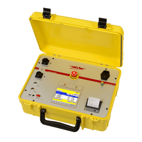
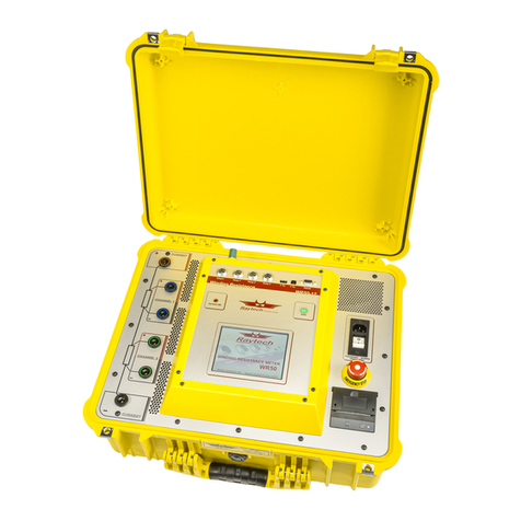
Raytech WR14 User manual

WR14
Winding Resistance Meter 15A
WR50-12 / 13
Winding Resistance Meter 50A
Raytech USA, Inc., 118 South 2nd Street, Perkasie, PA 18944
INSTRUCTION MANUAL
ENGLISH

Instruction Manual Winding Resistance Meter
Type WR50, WR14, Version 2.01 Page 2 of 85
Contents
1 Safety Precautions .......................................................................................................... 4
2 Unpacking ....................................................................................................................... 6
2.1 WR50...................................................................................................................... 6
2.2 WR14...................................................................................................................... 7
3 Introduction...................................................................................................................... 8
3.1 General................................................................................................................... 8
3.2 Advantages & Features........................................................................................... 9
3.3 System Details.......................................................................................................10
4 Quick Start Guide...........................................................................................................11
4.1 Instrument operation..............................................................................................11
4.2 Selecting the proper current range.........................................................................12
4.3 Connection to Test Object......................................................................................12
5 Operation Elements........................................................................................................17
5.1 WR50.....................................................................................................................17
5.2 WR14.....................................................................................................................20
6 Operating Menu..............................................................................................................23
6.1 Menu Structure ......................................................................................................23
6.2 Main Menu.............................................................................................................24
6.2.1 Main Menu Screen ................................................................................................................ 24
6.2.2 Start....................................................................................................................................... 25
6.2.3 Store...................................................................................................................................... 25
6.2.4 Stop....................................................................................................................................... 25
6.2.5 Demag................................................................................................................................... 26
6.2.6 Setup..................................................................................................................................... 27
6.2.7 General.................................................................................................................................. 28
6.2.7.1 Mouse Cursor...................................................................................................... 28
6.2.7.2 Alternative Caption .............................................................................................. 28
6.2.7.3 MUX A / MUX B................................................................................................... 29
6.2.7.4 Length Correction................................................................................................ 30
6.2.7.5 License................................................................................................................ 31
6.2.7.6 Firmware update.................................................................................................. 32
6.2.7.7 Language............................................................................................................. 32
6.2.7.8 Clock Settings...................................................................................................... 33
6.2.7.9 About................................................................................................................... 34
6.2.7.10 USB Printer.......................................................................................................... 34
6.2.7.11 Service Mode....................................................................................................... 35
6.2.7.11.1 Calibrate Touchscreen....................................................................... 35
6.2.7.11.2 WR14 Ground Warning ..................................................................... 36
6.2.8 Mode ..................................................................................................................................... 37
6.2.8.1 Single .................................................................................................................. 37
6.2.8.2 Continuous .......................................................................................................... 37
6.2.8.3 Interval................................................................................................................. 38
6.2.9 Range.................................................................................................................................... 40
6.2.10 Temp. Corr. ........................................................................................................................... 41
6.2.11 Colors.................................................................................................................................... 44
6.3 Results...................................................................................................................45
6.3.1 Print....................................................................................................................................... 45
6.3.2 Delete.................................................................................................................................... 45
6.3.3 Open...................................................................................................................................... 46
6.3.4 Export.................................................................................................................................... 47
6.3.5 HRT....................................................................................................................................... 47
6.4 Battery Operation WR14........................................................................................48
6.4.1 Low Battery ........................................................................................................................... 49
7 Options...........................................................................................................................50
7.1 Temperature Measurement....................................................................................50
Instruction Manual Winding Resistance Meter
Type WR50, WR14, Version 2.01 Page 3 of 85
7.2 Heat run test Software ...........................................................................................51
7.2.1 Introduction............................................................................................................................ 51
7.2.2 Measurement with interval mode for HRT ............................................................................. 52
7.2.3 Analysing the HRT Results.................................................................................................... 54
7.2.3.1 Showing the graph in °C...................................................................................... 56
7.3 Cable extension.....................................................................................................58
7.3.1 2040N-05003......................................................................................................................... 58
7.3.2 2041N-05003......................................................................................................................... 59
7.3.3 2043N-05000......................................................................................................................... 60
8 Technical Specification...................................................................................................61
8.1 WR50.....................................................................................................................61
8.2 WR14.....................................................................................................................62
9 Interfaces........................................................................................................................63
9.1 Hardware...............................................................................................................63
9.1.1 RS 232 .................................................................................................................................. 63
9.1.2 USB....................................................................................................................................... 63
9.1.3 USB....................................................................................................................................... 63
9.1.4 Extern.................................................................................................................................... 64
9.1.4.1 Standard type...................................................................................................... 64
9.1.4.2 Example for connecting an external warning device............................................ 65
9.1.4.3 Extended Safety Circuit type ............................................................................... 65
Appendix
A Raytech Toolbox.............................................................................................................69
B Software Development Kit SDK......................................................................................70
C Command Syntax...........................................................................................................71
C.A Serial Interface..................................................................................................................................... 71
C.B USB Interface....................................................................................................................................... 72
D USB Printer Info..............................................................................................................73
E Measuring high- and low-voltage-side in series ..............................................................74
F Demagnetizing................................................................................................................77
G Multiplexer......................................................................................................................79
H Warranty Conditions.......................................................................................................80
I Error Messages..............................................................................................................82
J Trouble Shooting............................................................................................................84
K Contacts.........................................................................................................................85

Instruction Manual Winding Resistance Meter
Type WR50, WR14, Version 2.01 Page 4 of 85
1 Safety Precautions
The following safety precautions must be observed during all phases of operation, service,
and repair of this instrument. By purchasing this equipment the purchaser assumes all
liability for the operation and use of this equipment. The intended use of the instrument, its
design and manufacture, is to be conducted within the precautions or other specific warnings
located within this manual. Failure to comply with these precautions and other specific
warnings violates safety standards of design, manufacture, and intended use. Raytech USA,
Inc. assumes no liability for the operation and use of this equipment.
SAFE OPERATION
Only qualified knowledgeable persons should be permitted or attempt to operate this test
equipment. All test personnel should fully familiarize themselves with the correct application
and operation of this and all test equipment prior to operation. Persons directly and indirectly
engaged in the operation of this test equipment should keep clear of all high voltage
apparatus while conducting tests and measurements.
WARNING!
Never connect the instrument to an energized transformer.
GROUND THE INSTRUMENT
The power cord supplied with the equipment must be connected an electrical receptacle with
an electrically grounded terminal (Earthed Ground). To minimize shock hazard, the Ground
Terminal on the instrument must be properly connected to an Earth grounded point. In many
cases, the quality of the safety ground terminal provided by the power cord does not fulfil the
safety requirements.
Non grounded instruments are dangerous and may cause Personnel and instrument
damage.
BEFORE APPLYING POWER
Read this manual carefully before operating the system. The WR14 is battery operated, the
WR50-12 and the WR50-13 are line operated. They operate from a wide range power input
from 90 to 264Vac and 47…63Hz with automatic ranging.

Instruction Manual Winding Resistance Meter
Type WR50, WR14, Version 2.01 Page 5 of 85
KEEP AWAY FROM LIVE CIRCUITS
Operating personnel must not remove instrument covers. Component replacement and
internal repairs must be made by qualified service personnel. Do not replace components or
service this instrument with the power cable connected. To avoid injuries, always discharge
circuits, disconnect power and remove external voltage sources before touching
components.
DO NOT OPERATE IN AN EXPLOSIVE ATMOSPHERE:
Do not operate the instrument in the presence of flammable gases or fumes.
DO NOT SUBSTITUTE PARTS OR MODIFY INSTRUMENT:
Because of the danger of introducing additional hazards, do not install substitute parts or
perform any unauthorized modification to the instrument. Return the instrument to a Raytech
service department for service to ensure proper operation and that safety features are
maintained.
Instruments, which appear damaged or defective, should be made inoperative and secured
against unintended operation until they can be repaired by qualified service personnel.

Instruction Manual Winding Resistance Meter
Type WR50, WR14, Version 2.01 Page 6 of 85
2 Unpacking
2.1 WR50
The Instrument consists of the following items:
The Instrument Power Cord Accessories:
(depending on country 2 Paper Rolls
of distribution) and 2 fuses
Current cables Jumper cable Cable Bag
(2 cables with WR50-13)
Potential cables: Channel 1 Potential cables: Channel 2 Potential cables: Channel 3
(only WR50-13)
USB Memory Stick Instruction Manual

Instruction Manual Winding Resistance Meter
Type WR50, WR14, Version 2.01 Page 7 of 85
2.2 WR14
The Instrument consists of the following items:
The Instrument Power Cord Accessories:
(depending on country 2 Paper Rolls
of distribution)
Current cables Jumper cable Cable Bag
Potential cables: Channel 1 Potential cables: Channel 2 USB Memory Stick
Instruction Manual
If any of the above items are missing or damaged contact your local representative or
Raytech USA, Inc. immediately. Optional test leads may be ordered (other than shown).

Instruction Manual Winding Resistance Meter
Type WR50, WR14, Version 2.01 Page 8 of 85
3 Introduction
3.1 General
Raytech Digital Winding Resistance meters are the enhanced version winding resistance
system with a most advanced demagnetizing circuit. They are designed for high degree of
accuracy for the measurement of very low resistance of inductive loads.
Ease of use: This intelligent system has an easy to use operation screen, which allows quick
selection of the current level to be measured. This system incorporates a touchscreen which
allows the user easy access to change or activate a feature.
Impressive Accuracy: The WR series of instruments have high precision, fully automatic,
multi-microprocessor based architecture. These systems are designed for highly accurate
readings on-site with laboratory precision.
Unique Measuring Technique: This newly designed technique of measurement
incorporates a high precision measurement circuit, a unique power source and the fastest
discharge unit on market. Extensive filtering and high precision standards are used within the
test system. The WR50 is capable of precision measurements up to 50A, The WR14 up to
15A.
Operation: The WR series of instruments apply a preset current level, selected by the user,
from 0.025A to 50A (WR50) or 0.025A to 15A (WR14). The 50V
1
power source quickly
charges the load and the results of the test are displayed within a few seconds automatically.
The results are reported on the easy-to-read color LCD display and can be stored or printed.
Compact Design: The WR50 and the WR14 are lightweight systems designed with their
own rugged waterproof field cases.
NOTE
The WR field case is a waterproof design. When the case is unlocked,
a small hole automatically opens, to compensate atmospheric
pressure changes.
Simple Maintenance: There is no maintenance required. There is no calibration procedure
(no potentiometers to turn). This is due to the utilization of high precision components in the
design.
Advanced Protection: Upon powering on the system initializes itself with a self-calibrating,
circuit checking sequence. If any problems are detected during this initialization period, or
during operation, the operator is immediately notified. The system constantly monitors the
condition when turned on. The WR series have extensive protection built in to the circuitry.
This is one of the many reasons we can extend our warranty to 5 years.
1
WR14: 30V

Instruction Manual Winding Resistance Meter
Type WR50, WR14, Version 2.01 Page 9 of 85
3.2 Advantages & Features
Highest Accuracy and Precision of any high current test system
Automatic measurements of Low Resistance from 0.00 ...100k
Demagnetizing Circuit (Advanced design)
Microprocessor based system with internal storage for over 10000 test results
Data exchange via USB-Key
Storage and Printing of test results while the test system is measuring
Complete automatic calibration system and system diagnostics
Temperature channels with automatic resistance correction
Standard USB 1.1 & RS232 (serial) Interface
Pure filtered DC Power source for the highest accuracy readings
Automatic, high efficiency cooling system to dissipate internal temperatures
Automatic shut off for over-temperature condition
Color LCD with backlighting and touch screen
Panel mounted Emergency Stop Switch
Mounted in rugged case for field testing
Fully automatic cooling curve analysis (option AHRT 01)
Fastest discharge time in the market
5 Year standard warranty

Instruction Manual Winding Resistance Meter
Type WR50, WR14, Version 2.01 Page 10 of 85
I
U
R
3.3 System Details
System Check:
The instruments are line operated
1
. The systems are designed to be used with AC Voltage
power sources between 90 to 264VAC 47…63Hz. The systems perform a self-check each
time that they are powered on. The User should always visually inspect all connectors,
cables and devices to be measured to avoid any safety issues.
Limitations of Winding Resistance Testing:
In general, there are no limitations on testing low or high inductive windings of transformers.
The test systems are specially designed to test all transformer windings.
Discharging the Transformer windings:
The WR systems are specialized systems designed to measure Transformer windings. These
systems are equipped with heavy-duty discharge circuits that are very unique in design.
The internal discharge circuit dissipates the stored energy in the transformer windings with a
“Constant Power Discharge Circuit” that is unique to all transformer winding test systems.
That is the reason why Raytech systems can discharge transformers more than 10 times faster than
any other system on the market.
If a cable happens to fall off during test, the system will STILL discharge the test object safely with
the automatic Constant Power Discharge Circuit.
The Potential Test Leads are part of the safety circuit and have the ability to discharge a transformer
should one of the current leads become detached.
DO NOT USE A SMALLER GAUGE POTENTIAL CABLES (Channel 1, 2, or 3) THEN THE
ORIGINAL RAYTECH CABLES SUPPLIED!
Low Resistance Testing:
The WR series of test instruments utilize a 4 wire measuring technique for each Channel.
The points where the potential leads are connected determine the resistance reading.
The test set employs a very simple principle of Ohm’s law:
R= Resistance
U= Voltage
I= Current
1
The WR14 is also battery operated additionally to the line operation

Instruction Manual Winding Resistance Meter
Type WR50, WR14, Version 2.01 Page 11 of 85
4 Quick Start Guide
4.1 Instrument operation
For examples of Transformer connections; See next page
1. Power on the instrument 2. Select the Test Current:
press Range or Setup / Range
3. Press start button 4. Get the results
5. Press stop button
WARNING!
Wait until the green light shows
“Safe” before disconnecting the
cables

Instruction Manual Winding Resistance Meter
Type WR50, WR14, Version 2.01 Page 12 of 85
4.2 Selecting the proper current range
Ensure that the test current does not exceed 10% of the rated winding current. This could
cause erroneous reading due to heating in the winding.
4.3 Connection to Test Object
Always check the winding schematic on the nameplate and trace the current path through
the windings.
You can save time if you measure the high voltage side in series to the low voltage side from
the same magnetic core. Because there are more turns on the high voltage side, you reach
much faster saturation flux in the core. This helps to stabilize the measurement and saves
much time.
The potential leads must be connected between the current leads. Do not clip the potential
leads to the current leads.

Instruction Manual Winding Resistance Meter
Type WR50, WR14, Version 2.01 Page 13 of 85
Single Phase Transformer, Vector Group 0
Measurement of HV and LV Winding

Instruction Manual Winding Resistance Meter
Type WR50, WR14, Version 2.01 Page 14 of 85
Three Phase Transformer, -Vector Group 0
Measurement of HV and LV Winding

Instruction Manual Winding Resistance Meter
Type WR50, WR14, Version 2.01 Page 15 of 85
Three Phase Trafo -
Measurement of one LV Winding

Instruction Manual Winding Resistance Meter
Type WR50, WR14, Version 2.01 Page 16 of 85
Three Phase Transformer, -
Measurement of two LV Winding

Instruction Manual Winding Resistance Meter
Type WR50, WR14, Version 2.01 Page 17 of 85
5 Operation Elements
5.1 WR50
1
1
The picture is from a WR50-12, the WR50-13 additionally has a 3rd channel

Instruction Manual Winding Resistance Meter
Type WR50, WR14, Version 2.01 Page 18 of 85
1: Main Input, Main Switch, Fuses
Connect the power cable to the Main Input.
Press the Main Switch to switch the WR50 on / off.
A 10A T (slow blow) fuse protects the device. Use only the correct fuse type to replace it.
2: Emergency Stop
Press to stop: The measurement will stop and immediately start to discharge the
Transformer.
Turn clockwise to release. The device will remain in a safe mode state.
3: Thermal Printer
Allows you to quickly get your results on paper by using the built-in thermal printer.
4: Safety Indicator
Green Light on: System is in safe mode. Ready for handling connections.
Red Light on: Unsafe mode! Don’t remove any cables, there is current flowing and
voltage on the test leads!
The Transformer is not discharged!
5: Display with Touch Panel
The instrument can be easily manipulated and fully controlled by the touch screen panel. If
preferred, an external mouse or keyboard can be connected to the USB Port to control the
system.
6: Sense receptacle
Connect + and – Sense Cable for each channel to test object.
(Channel 3: only WR50-13)
7: Current receptacle
Connect + and – Current Cable to test object.
8: Extern
This port can be used for en external warning device.
See chapter “9.1.4 Extern” on page 64 for details.

Instruction Manual Winding Resistance Meter
Type WR50, WR14, Version 2.01 Page 19 of 85
9: Earth
Use this terminal to connect an additional ground line.
10: Temperature receptacle
Each receptacle accommodates an external temperature probe. (maximum 3)
(Optional 10m Accessory 2021N-26001)
11: USB Interface
1 x USB Host
1 x USB Device
See chapter “9.1.2 USB” on page 63 for details.
12: RS Interface
RS232
See chapter “9.1.1 RS 232” on page 63 for details.

Instruction Manual Winding Resistance Meter
Type WR50, WR14, Version 2.01 Page 20 of 85
5.2 WR14
The solution com pany
88-264VAC/47-63Hz
ON/OFF
CHARGE
Temp 2
Temp 1
Extern
Current ON Safe RS232
88-264VAC/47-63Hz
S
T
O
P
E
M
E
R
G
E
N
C
Y
14: Main Input
2: Main
Switch
1: Charge
Indicator
3: RS Interface
1 x RS232
4: USB Interface
1 x Host
1 x Device
5: Thermal
Printer
6: Display with
Touch Panel
7: Earth
8: Extern
9: Temperature
receptacle 1...2
10: Sense
receptacle
11: Current
receptacle
12: Safe
Indicator
13: Emergency
Stop
.
Other manuals for WR14
1
This manual suits for next models
2
Table of contents
Other Raytech Measuring Instrument manuals

Raytech
Raytech WR14-R User manual

Raytech
Raytech MC2 User manual

Raytech
Raytech WR14 User manual

Raytech
Raytech Micro Junior 2 User manual

Raytech
Raytech SynchroKing 2 Mk2 User manual

Raytech
Raytech TraceTek TTDM-128 User manual

Raytech
Raytech Micro Junior 2 User manual

Raytech
Raytech TR-MARK III User manual

Raytech
Raytech SynchroKing 4S Mk2 User manual

Raytech
Raytech T-REX User manual