Raytools BM115 Series User manual

BM115 SERIES
6-12KW Auto-Focusing Laser Cutting Head- User Manual
Email: sales@raytools.ch
Add: EMMENTALSTRASSE 96 CH-3414 OBERBURG, SWITZERLAND

1 | 27
www.raytools.ch
BM115 SERIES 6-12KW Laser Cutting Head User Manual
Historical Version:
History
version
Date
Change the profile
Editors
Reviewers
Review date
V1.0
2018/8/22
Establish
Thank you for choosing our product!
This manual makes a detail introduction about the use of BM115 laser cutting head, including
installation, setup, operation and service etc. Please directly contact us if you have other things to
know.
Please read these instructions carefully before use the series cutting head and relative equips. This
will help you to use it better.
Because the product keeps renewing, please note the product you receive may differ slightly from
the illustrations in this manual in some aspects. We apologize for your inconvenience here.
Version
V1.0
Date:
2017/12/14

2 | 27
www.raytools.ch
BM115 SERIES 6-12KW Laser Cutting Head User Manual
Index
1Summary.................................................................................................................................. 4
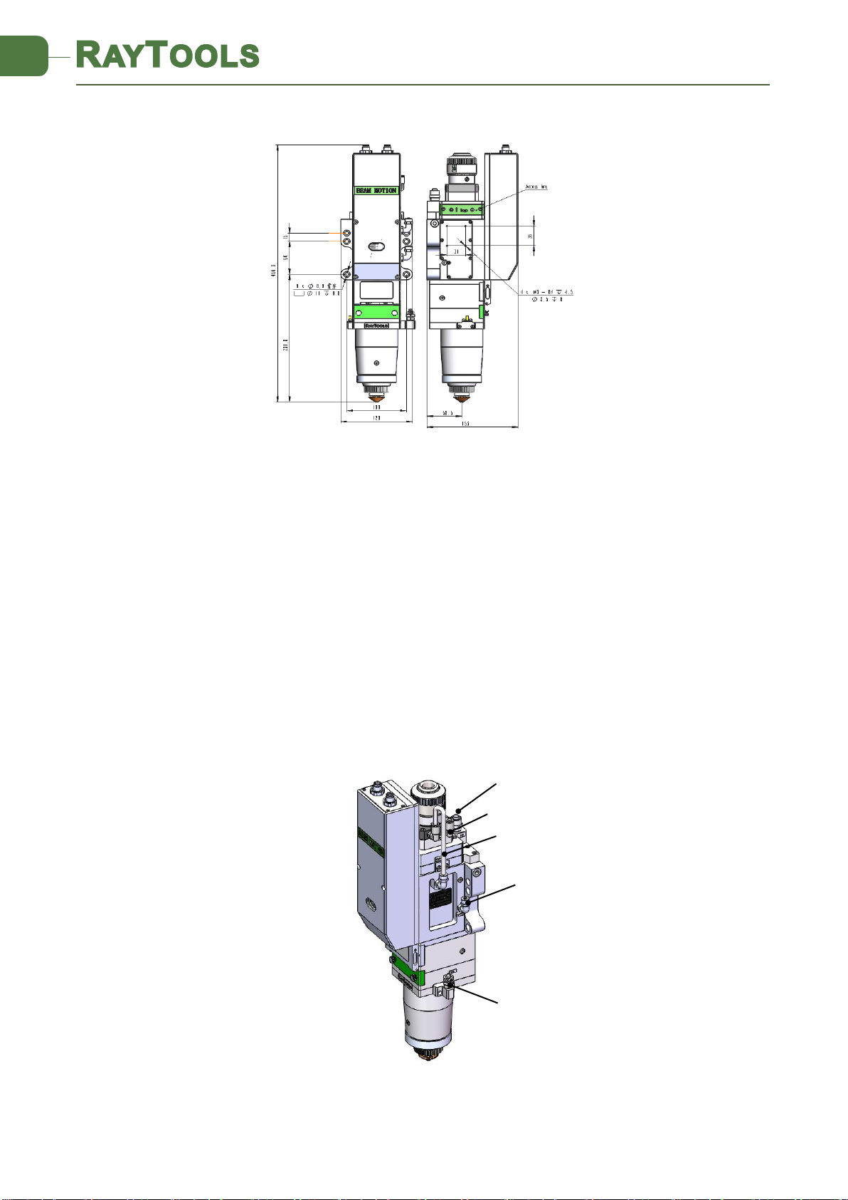
1.1 Structure................................................................................................................................4
2Mechanical Installation............................................................................................................ 4
2.1 Mounting ...............................................................................................................................4
2.2 Connection of Water Pipe and Gas Pipe ...............................................................................5
2.2.1 Water cooling interface ........................................................................................5
2.2.2 Assist gas interface ...............................................................................................6
2.3 Connection of Cutting Head Cable ........................................................................................7
2.3.1 Connection of Cutting Head and Cable ................................................................7
2.3.2 Cable connection to drive ....................................................................................7
2.4 Fiber Input Interface..............................................................................................................7
2.5 Fiber Insertion and Interface Direction Adjustment .............................................................8
3System Installation and Commissioning ..................................................................................9
3.1 ETC_F100 Installation (Auto focus by 0-10V analog) ............................................................9
3.1.1 Interface & Signal ...............................................................................................10
3.1.2 Wiring .................................................................................................................11
3.1.3 Dimension of ETC_F100......................................................................................13
3.1.4 Dimension of Drive.............................................................................................14
3.2 FSCUT (Cypcut) with position mode....................................................................................14
3.2.1 Wiring .................................................................................................................14
4Beam Adjustments and Focusing...........................................................................................17
4.1 Beam Adjustments (QBH interface) ....................................................................................17
4.2 The Focus Position Adjustment...........................................................................................18
5Maintenance..........................................................................................................................18
5.1 Cleaning Lens.......................................................................................................................18
5.2 Removal and Installation of Lenses .....................................................................................19
5.2.1 Removal and Installation of Cover Glass ............................................................19
5.2.2 Removal and Installation of Top Cover Glass .....................................................20
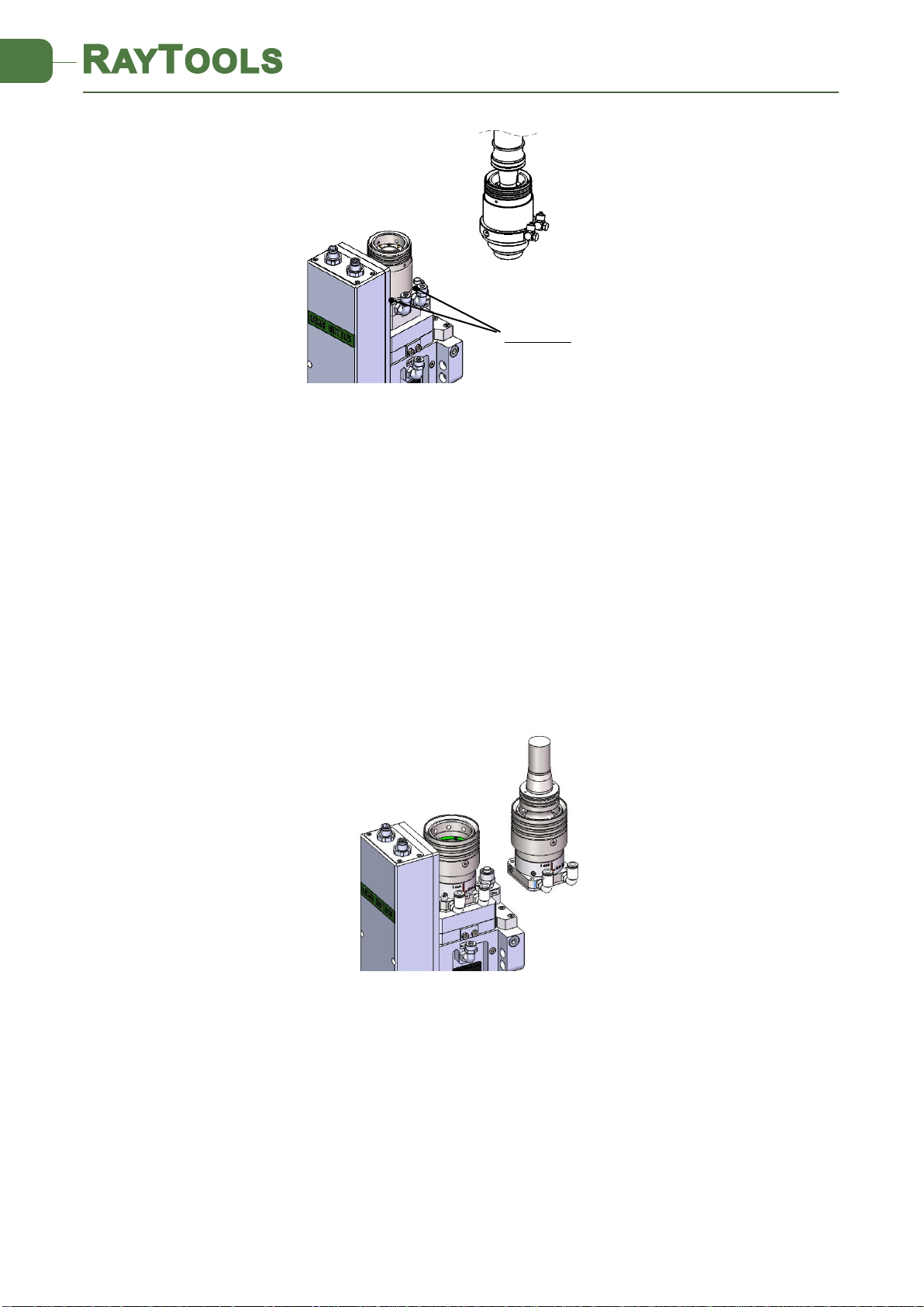
5.2.3 Removal and Installation of Collimating Lenses.................................................21
5.2.4 Removal and Installation of Focus Lenses..........................................................22
5.3 Replace Nozzle Connector...................................................................................................22
5.3.1 Replace Ceramic Body ........................................................................................23
5.3.2 Replace Nozzle....................................................................................................23
5.4 Troubleshooting of Drive .....................................................................................................23
5.4.1 Alarm information ..............................................................................................23
5.5 Common Problem Analysis..................................................................................................24
5.5.1 Servo calibration process terminated abnormally .............................................24
5.5.2 The screen is abnormally displayed ...................................................................25

3 | 27
www.raytools.ch
BM115 SERIES 6-12KW Laser Cutting Head User Manual
5.5.3 Z-axis coordinate drift.........................................................................................25
5.5.4 Input signal jitter or invalid ................................................................................25

4 | 27
www.raytools.ch
BM115 SERIES 6-12KW Laser Cutting Head User Manual
1Summary
1.1 Structure
BM115 laser cutting head includes fiber interface, collimation module, focus & beam alignment
module, cover glass module and nozzle module which is shown in figure 1.1.
2Mechanical Installation
2.1 Mounting
The mounting of BM115 to machine tool is shown in Figure 2.1. Customers are advised to
Install the laser head perpendicular to the bed surface as requested and make sure the laser
head is locked, which is one of the premises to ensure the stable cutting.
CAUTION: The Z-axis sliding base for fixing laser cutting head should be conductive to
machine tools and keep a good grounding.
Cable interface
Water inlet
Cutting gas
X-Y Adjustment
Nozzle cooling
Water outlet
Cover glass
Figure 1.1 — Function module and interface
Collimation module
Beam alignment module
Cover glass module
Nozzle assembly
QBH

5 | 27
www.raytools.ch
BM115 SERIES 6-12KW Laser Cutting Head User Manual
2.2 Connection of Water Pipe and Gas Pipe
2.2.1 Water cooling interface
BM115 laser cutting head is equipped with water cooling circuit for fiber interface, collimator
and focus module which could be found in figure 2.2. It is important to note that when the laser
power is greater than 500 watt, it is recommended to use water cooling. The recommended
water flow is as below.
The design of this water cooling interface is a closed loop.
Figure 2.1 — Mounting hole
Figure 2.2 —Water pipe and gas pipe
Water pipe
Water out
Cutting gas
Water in
Nozzle cooling by gas

6 | 27
www.raytools.ch
BM115 SERIES 6-12KW Laser Cutting Head User Manual
2.2.2 Assist gas interface
The impurity in assist gas such as hydrocarbon and steam will damage the lens and cause cutting
power fluctuation as well as inconsistencies between the sections of the work piece. The table
below is the recommended auxiliary gas specification. The higher the purity of the gas, the better
the quality of the cutting section.
Impurity can be filtered out in gas supply tube, but Oxygen and water vapor can permeate light
path through nonmetal materials, which is the source of the appearance of dust and
hydrocarbon. Stainless steel fittings are recommended, at the same time must use filters which
can remove a minimum of 0.01 micron particle to purify.
A pressure gauge with a stainless steel diaphragm is recommended. Industrial pressure gauges
suck in air. Rubber diaphragm produce hydrocarbon by aging or other factors.
N2 or fine filtered air with pressure less than 1 bar is recommended for nozzle cooling. The O2
is prohibited for nozzle cooling.
Outer diameter of water pipe caliber
6mm
Minimum flow speed
1.8 l/min(0.48 gpm)
Entry pressure
170-520kPa (30-60 psi)
Entry temperature
≥room temperature />dew point
Hardness (relative to CaCO3)
<250mg/liter
PH range
6 to 8
Particle size allowed
Diameter less than 200 microns
Gas
Purity
Maximum content of water vapor
Maximum content of hydrocarbon
oxygen
99.95%
<5 ppm
<1 ppm
nitrogen
99.99%
<5 ppm
<1 ppm
argon
99.998%
<5 ppm
<1 ppm
helium
99.998%
<5 ppm
<1 ppm
Diameter of auxiliary gas
pipe (Outer diameter)
10mm
Diameter of cooled gas
pipe (Outer diameter)
8mm

7 | 27
www.raytools.ch
BM115 SERIES 6-12KW Laser Cutting Head User Manual
CAUTION: Gas interface cannot be replaced arbitrarily, especially do not use PTFE TAPE,
Otherwise, the gas path will be blocked and cannot do normal cutting which will
damage cutting head at the same time.
2.3 Connection of Cutting Head Cable
2.3.1 Connection of Cutting Head and Cable
Connect the corresponding interface of cutting head to power cable and encoder cable as shown
in figure 2.3. To fix the cables into cable tray of machine tool after cable with proper length is
preserved.
2.3.2 Cable connection to drive
Connect power cable and encoder cable to the corresponding interfaces of drive according to
the definition on cable sleeve. The wiring of drive is to be as per the system installation and
commissioning.
CAUTION: The output signal of limiting sensor is NPN-NC;
CAUTION: All wiring shall be done when the power is disconnected and commissioning
could be commenced after inspection on wiring.
.
2.4 Fiber Input Interface
BM115 is applicable to most of industrial laser in market. It is equipped with collimator.
The connection between the end of the fiber and the cutting head is called fiber interface.
Commonly used fiber connectors include QBH, QD, etc, and every fiber interface has its unique
Figure 2.3 — Cable connection
Power cable
Encoder cable

8 | 27
www.raytools.ch
BM115 SERIES 6-12KW Laser Cutting Head User Manual
fixation method. Please refer to corresponding instruction of fiber interface.
WARNING: The optical components must be dust free and all dusts must be cleaned
before use. The fiber shall be horizontally inserted into fiber interface to prevent dust from
entering the interface and falling on the surface of the lens. Upper limit in the fiber before
fixing the laser head.
2.5 Fiber Insertion and Interface Direction Adjustment
The fiber insertion way is described as below by example of QBH.
Firstly, to align the red point at the end of the QBH interface to the red point of the handwheel;
Then remove QBH dustproof cover and ensure the red mark of fiber end aligned to red mark on
QBH of cutting head when you insert the fiber end straightly to bottom of QBH interface of
cutting head. Then turn the QBH handwheel clockwise. It is in place when you hear the "Da"
voice, then pull the handwheel up and turn clockwise to end. (see Figure 2.4)
If the red mark on fiber is too far away from the red dot on laser head interface when the fiber
connector is inserted into the interface causing an out of alignment insertion, you can refer to
steps below to adjust the position of fiber interface on laser head for solving the problem. As
shown in Fig. 2.4, unscrew the 4 locking screws of the position of the part icon with a wrench,
rotate the QBH interface and screw the locking screws after the red mark is in place.
The fiber insertion way is described as below by example of QD (LLK-D).
Firstly, to remove the dustproof cover and align the location pin of fiber end to U type slot of QD
interface. To pull the external edge downward and insert fiber straightly to bottom then release.
Check if there is any loose by slightly rotating fiber. (see figure 2.5)
Figure 2.4— Fiber insertion to QBH
Locking screw

9 | 27
www.raytools.ch
BM115 SERIES 6-12KW Laser Cutting Head User Manual
The fiber insertion way is described as below by example of Q+.
Firstly, to remove the dustproof cover and align the location pin of fiber end to U type slot of Q+
interface. To pull the external edge downward and rotate in anti-clockwise direction until the
mechanical part is locked. Then insert fiber straightly to bottom and rotate external edge of Q+
interface in clockwise direction then release. Check if there is any loose by slightly rotating fiber.
(see figure 2.6)
3System Installation and Commissioning
3.1 ETC_F100 Installation (Auto focus by 0-10V analog)
Figure 2.5— Fiber insertion to QD
Locking screw
Figure 2.6— Fiber insertion to Q+

10 | 27
www.raytools.ch
BM115 SERIES 6-12KW Laser Cutting Head User Manual
3.1.1 Interface & Signal
Interface
Descriptions
CON1
DB15 female connector, interface to servo driver.
CON2
Interface for connecting external IO devices.
CON3
Interface to 24V DC power supply.
CON4
Interface for connecting external IO devices.
Pins of CON1:
Pin
Descriptions
1
OUT_Servo_DA(Drive speed command)
2
Servo_TGON(Drive brake signal)
3
Servo_CLR(Drive alarm clear signal)
4
Servo_OS(Drive zero speed clamp, used to control motor lock
shaft)
5
PGND(Power ground)
6
E1_A_N(Encoder A negative)
7
E1_B_N(Encoder B negative)
8
E1_C_N(Encoder C negative)
9
AGND(Analog ground)
10
Servo_ALM(Drive alarm signal)
11
Servo_SON(Drive enable signal)
12
VDD_24V(Power supply)
13
E1_A_P(Encoder A positive)
14
E1_B_P(Encoder B positive)
15
E1_C_P(Encoder C positive)
Pins of CON2:
Pin
Descriptions
N/A
/
N/A
/
Alarm out
When alarm occurs, a high level signal is output, normally is high
impedance state.
Home
Homing input signal, active high.
AGND
Common ground of analog signals, analog signals include: focus set
input, focus feedback output.
Focus set
The input signal of focus setting, is analog.

11 | 27
www.raytools.ch
BM115 SERIES 6-12KW Laser Cutting Head User Manual
Focus
Feedback
Output the position of current focus, is analog.
Brake+
This signal is not connected (motor without brake)
Note:N / A is an undefined interface, please leave it blank.
Pins of CON4:
Pin
Descriptions
Emergency
Stop
When the accident occurs, press the emergency stop button to achieve
emergency stop, 24V effective.
N/A
/
Focus IN
Pos.
Output 24V when focus in position.
N/A
/
N/A
/
Focus
Enable
High-level control focus on, low-level control focus off.
Down limit
The input signal of down limit, NPN.
Up limit
The input signal of up limit, NPN.
Note:N / A is an undefined interface, please leave it blank.
The above table shows only for factory default settings for the ETC-F100 controller.
BM115 achieves the auto focus by movement of collimation lens group and the focus adjustment
range is based on movement of collimation lens. When the collimation lens moves 1mm, it
conducts the movement of focus point by 2.25mm or 4mm.
Optical configuration
Scale range
Auto focus range
CL100mm/FL150mm
-10 to +10mm
-22.5 to +22.5mm
CL100mm/FL200mm
-10 to +10mm
-40 to +40mm
3.1.2 Wiring
The motor is an AC servo motor, which is connected to 220V AC L and N at the drive terminals
L1, L2, L1C and L2C. Details of connection method is shown in figure 3.1.
Limit signal: the limit diagram is shown in figure 3.2.
Brown
White & Brown
Green
White & Green
+24V
0V
Up limit
Low limit
Note: the limit sensor is NPN-NC and it continuously outputs 0V signal when it is not triggered.

12 | 27
www.raytools.ch
BM115 SERIES 6-12KW Laser Cutting Head User Manual
Figure 3.1—ETC_F100 Wiring instruction

13 | 27
www.raytools.ch
BM115 SERIES 6-12KW Laser Cutting Head User Manual
Note: Limit sensor is NPN-NC and outputs 0V continuously when it is not triggered.
3.1.3 Dimension of ETC_F100
Figure 3.3 —Overall size of ETC-F100 controller (unit: mm)
Figure 3.2—limit diagram

14 | 27
www.raytools.ch
BM115 SERIES 6-12KW Laser Cutting Head User Manual
3.1.4 Dimension of Drive
3.2 FSCUT (Cypcut) with position mode
3.2.1 Wiring
The motor is AC servo motor, which should connect the end of the drive L1, L2 , L1C and L2C to
AC 220V L and N. Please refer to figure 3.5 for the wiring diagram and figure 3.4 for the drive
installation size
Limit signal:As shown in figure 3.2
Brown
White & Brown
Green
White & Green
+24V
0V
Up limit
Low limit
Note: The limit sensor is NPN-NC and it continuously outputs 0V signal when it is not triggered.
Figure3.4 —Overall size of drive (unit: mm)

15 | 27
www.raytools.ch
BM115 SERIES 6-12KW Laser Cutting Head User Manual
BM115 achieves the auto focus by movement of collimation lens group and the focus adjustment
range & pulse rate are based on movement of collimation lens. When the collimation lens moves
1mm, it conducts the movement of focus point by 2.25mm or 4mm.
Optical configuration
Scale range
Auto focus range
CL100mm/FL150mm
-10 to +10mm
-22.5 to +22.5mm
CL100mm/FL200mm
-10 to +10mm
-40 to +40mm
Open the platform configuration tool to enter the reference value as shown in Figure 3.6 and
Figure 3.7. (Just for reference)
Figure3.5 — Position loop FSCUT wiring diagram

16 | 27
www.raytools.ch
BM115 SERIES 6-12KW Laser Cutting Head User Manual
Figure 3.6 — Platform configuration tools (BM115, CL100:FL150)
-22mm
4.4mm
22mm
35mm/s
22mm
35mm/s
1500mm/s
NC
/
-
·

17 | 27
www.raytools.ch
BM115 SERIES 6-12KW Laser Cutting Head User Manual
4Beam Adjustments and Focusing
4.1 Beam Adjustments (QBH interface)
Cutting quality in a great extent depends on whether the lens is in the middle. If the lens is not
in the middle, the laser beam may contact with nozzle or inner wall to produce high temperature
deformation. Lens centering operation should be considered when nozzle is replaced or the
cutting quality declines.
Lens centering of laser cutting head can be finished by adjusting focus lens, X-Y direction. The
adjusting screw is located on the top of the cutting head as shown in Figure 4.1. By using inner
hexagon spanner can loosen or screw the adjusting screw until the beam is located in the middle
of nozzle. Make sure the laser beam output from the center of nozzle. A method commonly used
tape dotting method:
-44mm
44mm
8.8mm
35mm/s
44mm
35mm/s
1500mm/s
NC
Figure 3.7 — Platform configuration tools (BM115, CL100:FL200)
·
/
-

18 | 27
www.raytools.ch
BM115 SERIES 6-12KW Laser Cutting Head User Manual
Pick a scotch tape, flatten it, and attach it to the nozzle tip;
Open the inner guiding red light of the laser. Find and observe the position of nozzle center that
the red light in the scotch tape relative to;
Next open and adjust laser generator at the range of 80W-100W and dot manually.
Tear off the tape and check the hole in the center of the nozzle;
Repeat the above steps to find the optimum relative nozzle center position of the beam;
This adjustment requires a series of adjustments, which is the basic operation of general laser
beam adjustment.
4.2 The Focus Position Adjustment
BM115 is equipped with automated focusing system. But it still needs dot manually to redefine
the focus position when it initially sets or lenses and lasers are replaced. For details about
operating system parameters, please refer to the system instructions.
Manual dot can refer to the following steps:
1. To attach one textured tape on nozzle tip and adjust the scale to biggest value, and set
laser power to 80-100w;
2. While moving each 0.5mm (as small as possible), shot a hole on the textured tape;
3. Dotting several times, finally compare and find out the scale corresponding to the
smallest hole is zero focus. The focus is just at the tip of the nozzle.
5Maintenance
5.1 Cleaning Lens
It’s necessary to maintain lenses regularly because of the characteristic of laser cutting process.
Figure 4.1— Beam adjustment
X-Y Adjusting screw
Dustproof Cover

19 | 27
www.raytools.ch
BM115 SERIES 6-12KW Laser Cutting Head User Manual
Cleaning to the cover glass once a week is recommended. The collimating lenses and focusing
lenses are recommended to be cleaned once every 2~3 months. In order to facilitate the
maintenance of the cover glass, the cover glass holder adopts a drawer type structure. (Figure
5.1)
Lens cleaning
a. Tools: Dust-proof gloves or fingertip, polyester swab, absolute ethanol, rubber gas blow
(purely compressed air).
b. Cleaning instruction:
1. To put fingertip onto left thumb and index finger.
2. Spray absolute ethanol onto the polyester swab.
3. Hold the edge of the lens with left thumb and index finger gently. (note: avoid touching
the surface of the lens by fingertip in case of trace)
4. Hold the lens to face eyes by left hand and hold the polyester swab by right hand. Wipe
the lens gently in single direction, from bottom to top or from left to right (Should not
wipe back and forth in case of secondary pollution to lens) and use rubber blow (purely
compressed air) to blow the surface of the lens. Both surfaces should be cleaned. After
cleaning, make sure that there is no residual like detergent, floating ash, foreign matters
and impurities.
5.2 Removal and Installation of Lenses
The whole process needs to be completed in a dust free room. Wear dust-proof gloves or
fingertips when removing or installing the lenses.
5.2.1 Removal and Installation of Cover Glass
The cover glass is wearing part which needs to be replaced once it is damaged.
As shown in Figure 5.2, open the buckle to pull out cover glass holder by pinching 2 edges
of drawer type holder.
Remove the pressing ring of the cover glass and cover glass after wearing fingertips
Clean the cover glass, cover glass holder and seal ring. The elastic seal ring should be
replaced if it is damaged.
Install the cleaned cover glass (Regardless of the front or back surface) into the holder
of cover glass.
Figure 5.1 —Replacement of cover glass
Cover glass holder
Table of contents
Other Raytools Industrial Equipment manuals
Popular Industrial Equipment manuals by other brands

Siemens
Siemens 8MF1 Series operating instructions

ABB
ABB HT564187 Operation manual

turck
turck PK01VR P Series quick start guide

Emerson
Emerson Shafer Installation, operation and maintenance manual

SCHUNK
SCHUNK TANDEM KRP3 Translation of original operating manual

R.V.R. Elettronica
R.V.R. Elettronica VJ1000HP user manual

Versum Materials
Versum Materials GASGUARD AP10 Installation, operation & maintenance manual

HYDAC International
HYDAC International MAFH-A Operating Maintenance and Troubleshooting Manual

ABB
ABB UBB Series Installation and commissioning guide

Wadkin
Wadkin RM Planer Spare Parts & Service

ABB
ABB HT604576 Operation manual

Delta
Delta Dometic CDF 11 quick guide