Raytools BW101-GS Series User manual

BW101-GS SERIES
2KW Handheld Laser Processing Head (Single Galvo Type)- User Manual

V1.2 RayTools AG © Copyright
www.raytools.ch
BW101-GS SERIES 2KW Handheld Laser Processing Head-User Manual
Thank you for choosing our product!
This manual describes the installation and commissioning of laser head in details so that you can
use this product quickly. You can consult us directly for more details.
Due to the continuous updating of product functions, the product you receive may differ from the
introduction in this manual in some aspects.
We reserve all rights in this document including the issued patents and other registered
commercial ownership related to this document. It is strictly prohibited to use this document in an
improper way especially to copy and disseminate it to third parties.
If you find any errors in this document, please inform us as soon as possible. The data contained in
this manual is only used to describe the product and shall not be regarded as a statement of
security interest.
For the benefit of our customers, we will constantly try to ensure that the products we develop
comply with the latest technology.
RayTools AG
Email: sales@raytools.com
Website: www.raytools.ch

V1.2 RayTools AG © Copyright
www.raytools.ch
BW101-GS SERIES 2KW Handheld Laser Processing Head-User Manual
Disclaimer
⚫We reserve the right to change the design in order to improve the quality or expand the
application or comply to manufacturing workmanship.
⚫We will not bear any responsibility for losses and accidents caused by wrong operation or
improper handling of our products.
⚫Dismantling of product will lose all warranty claims excluding the normal replacement of worn
parts and components required for maintenance or commissioning operations.
⚫Unauthorized modification of products or use of non-original spare parts will directly lead to
the invalidation of warranty and liability exemption.
⚫It is recommended to only use the spare parts provided by us or submit them to us or the
designated professional team for installation.
Use Regulations
⚫Ensure that the product is used in a dry environment.
⚫Ensure that the product is used in the environment required by EMC standards.
⚫The product is only allowed to run within the parameters specified in the technical data.
Personnel Responsibilities
⚫Be familiar with the basic provisions of work safety & accident prevention and have received
equipment operation guidance.
⚫Read and understand basic safety instructions and operations.
⚫You must have studied the relevant regulations and safety instructions and understand the
possible hazards.
⚫Comply with relevant regulations and implement corresponding protective measures.
Safety Instructions
Prevent Electric Shock
⚫Parts of the laser head such as nozzle, sensor, sensor interface and attached fasteners

V1.2 RayTools AG © Copyright
www.raytools.ch
BW101-GS SERIES 2KW Handheld Laser Processing Head-User Manual
may not be fully protected by the ground wire due to function fault. These parts may have low
voltage. When installing electrical equipment, please pay attention to taking anti electric shock
measures for relevant personnel.
Guard against Danger
⚫Never put your hands or other body under the laser head.
⚫Repair and maintenance work can only be carried out after the power is turned off.
⚫Do not exceed the specified maximum pressure.
⚫It must be ensured that the laser head is in normal condition at all times.
⚫All fasteners such as bolts and nuts must be tightened.
Laser Caution
⚫Avoid direct laser radiation or scattering to the skin.
⚫Do not stare at the laser beam even when wearing optical equipment.
⚫Use special laser protective eyeglasses that meet the requirements of safety standards IEC
60825-1.
Prevent Waterway Corrosion
⚫In order to avoid corrosion, use the specified coolant and comply with relevant requirements
and specified maintenance intervals.
Noise Prevention
⚫The corresponding measures shall be specified or explained and observed in order to prevent
personnel from being harmed by noise when the cutting air pressure is high.
Storage and Transportation
⚫Observe the storage temperature range allowed by the technical data.
⚫Take reasonable measures to prevent fire, vibration or impact.
⚫Do not store in or near the magnetic field.

V1.0 RayTools AG © Copyright
www.raytools.ch
BW101-GS SERIES 2KW Handheld Laser Processing Head -User Manual
Index
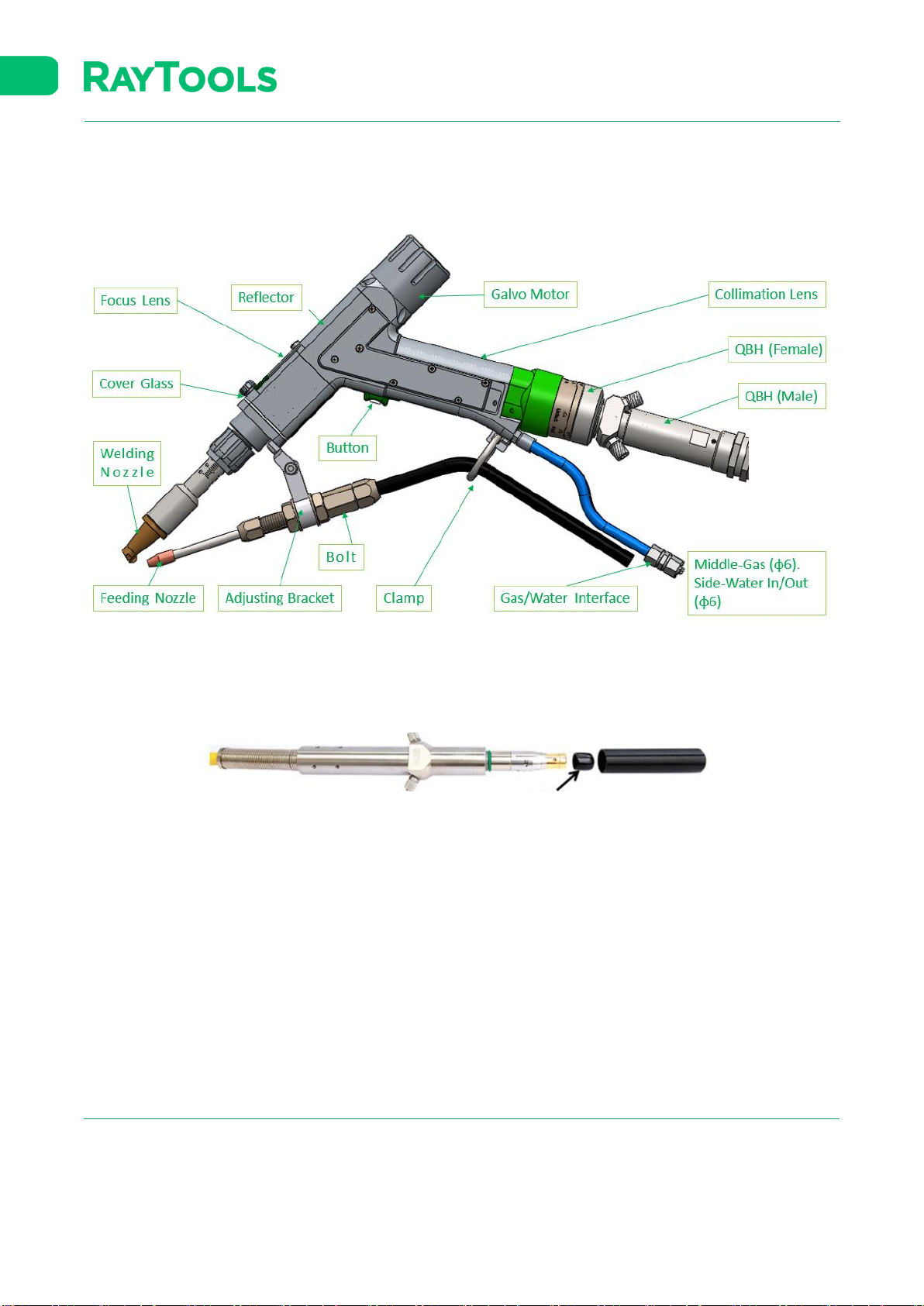
1Laser Processing Head ............................................................................................................1
1.1 QBH Connection...................................................................................................................1
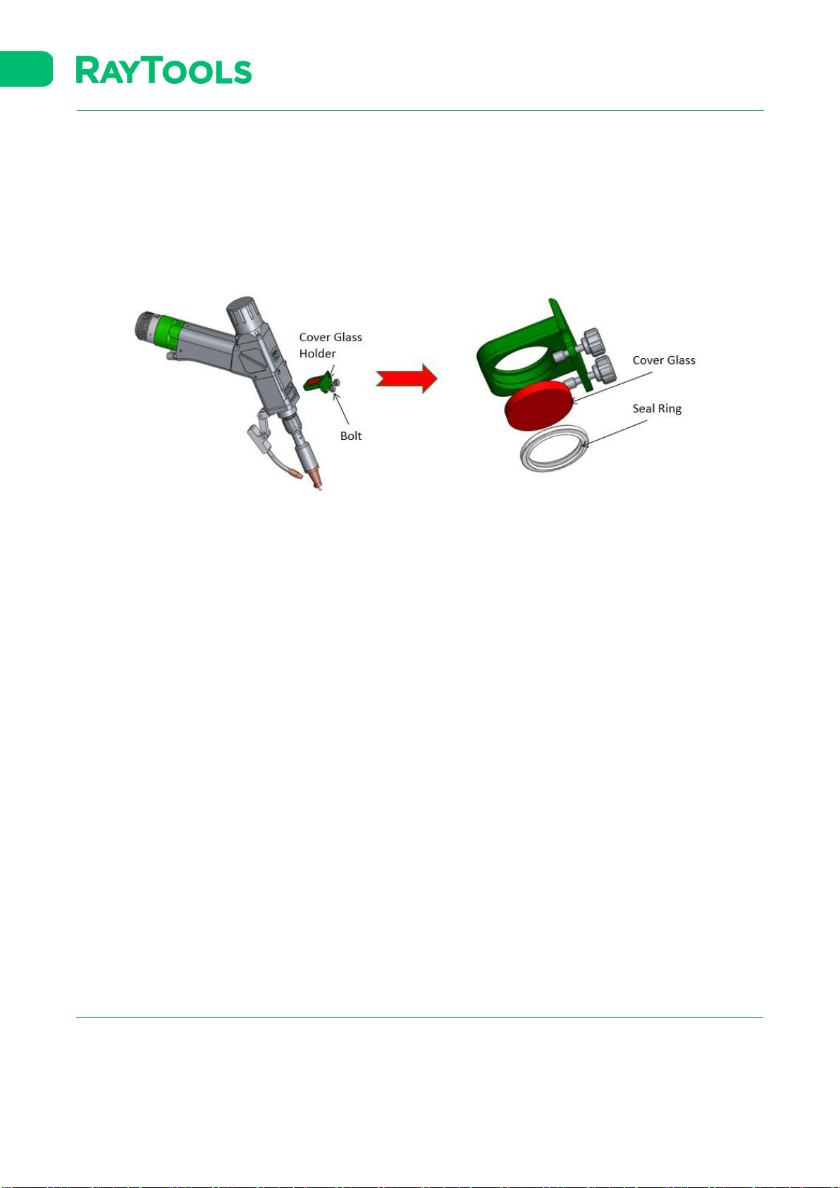
1.2 Dismantling and Mounting of Cover Glass...........................................................................2
1.3 Daily Inspection....................................................................................................................3
2Controller ................................................................................................................................4
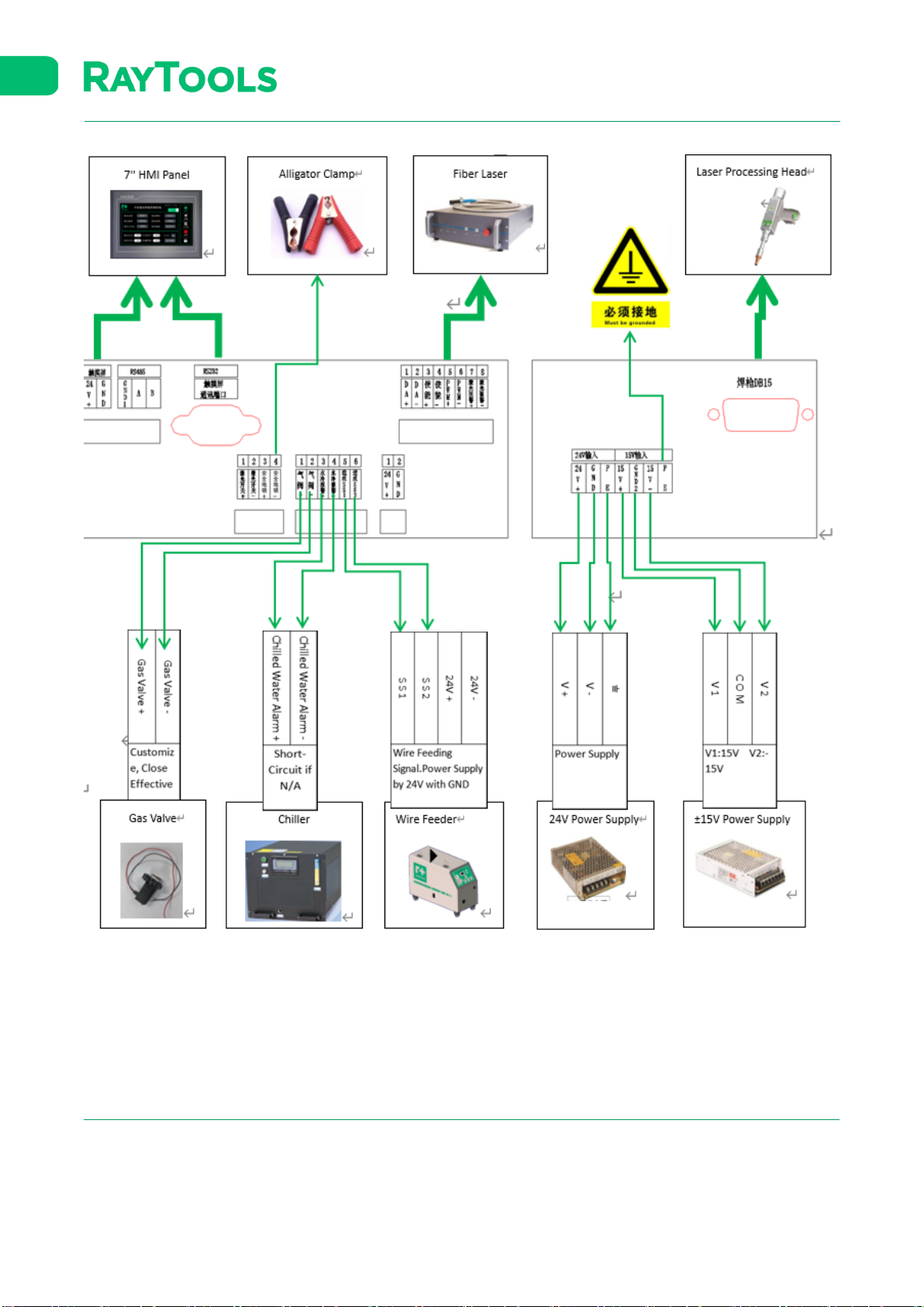
2.1 Overall Wiring.......................................................................................................................4
2.2 Wiring from HMI Panel to Controller ...................................................................................6
2.3 Wiring from Laser to Controller ...........................................................................................6
2.4 Wiring from Laser Processing Head to Controller................................................................7
2.5 Wiring from Power Supply to Controller..............................................................................7
2.6 Wiring from Gas Valve and Chiller to Controller ..................................................................9
2.7 Wiring from Wire Feeder to Controller..............................................................................10
3Wire Feeder...........................................................................................................................10
3.1 Installation of Wire Feeder.................................................................................................11
3.2 Operation of Wire Feeder ..................................................................................................13
3.3 Troubleshooting of Wire Feeder ........................................................................................16
3.4 Daily Maintenance of Wire Feeder.....................................................................................17
3.5 Supplementary Regulation of Auto Wire Feeding..............................................................18
4Connection of Wire Feeding Mechanism to Laser Processing Head ....................................18
5HMI........................................................................................................................................19
5.1 Home ..................................................................................................................................19
5.2 Setting.................................................................................................................................20
5.3 Process................................................................................................................................22
5.4 Monitoring..........................................................................................................................23
5.5 Function Switch ..................................................................................................................24
5.6 About..................................................................................................................................25
6Auxiliary Function .................................................................................................................25
6.1 Cut ......................................................................................................................................25
6.2 WeldSeam Clean.................................................................................................................29
6.3 Remote Clean .....................................................................................................................33
7Option Table of Welding Nozzle and Wire Feeding Nozzle...................................................36
8Troubleshooting Table...........................................................................................................37
9Reference Table of Welding Process.....................................................................................38

V1.0 RayTools AG © Copyright 1 |39
www.raytools.ch
BW101-GS SERIES 2KW Handheld Laser Processing Head-User Manual
1Laser Processing Head
1.1 QBH Connection
⚫Remove the dust cover of optical fiber and check whether the protective cap of fiber crystal head is locked.
Clean the optical fiber head with a dust-free cotton swab and absolute ethanol to ensure that the optical
fiber section is clean and dust-free.

V1.0 RayTools AG © Copyright 2 |39
www.raytools.ch
BW101-GS SERIES 2KW Handheld Laser Processing Head-User Manual
⚫Place the welding head horizontally.
⚫Align the red point at the end of the QBH interface to the red point of the handwheel.
⚫Remove QBH dustproof cover.
⚫Align the red mark of male fiber end to red mark on female QBH of cutting head when you insert the fiber end
straightly to bottom of QBH interface of cutting head.
⚫Turn the QBH handwheel clockwise. It is in place when you hear the "Da" voice, then pull the handwheel up and
turn clockwise to end.
1.2 Dismantling and Mounting of Cover Glass
1.2.1 Dismantling and Mounting of Middle Cover Glass
⚫Unscrew the bolt of focus lens holder in dust free environment to take out focus lens holder. The openings shall be
sealed with textured paper to prevent dust.

V1.0 RayTools AG © Copyright 3 |39
www.raytools.ch
BW101-GS SERIES 2KW Handheld Laser Processing Head-User Manual
⚫Take out seal ring and cover glass by lens tool for cleaning or replacement.
1.2.2 Dismantling and Mounting of Bottom Cover Glass
⚫Manually loosen the screw of the cover glass to pull out the holder. The openings shall be sealed with textured
paper to prevent dust. This cover glass is the outer one of double cover glasses.
⚫Remove the seal ring and carefully take out the cover glass for cleaning or replacement.
1.3 Daily Inspection
⚫Check whether the cover glass is polluted before daily use and replace it if necessary.
⚫Check whether the QBH connector is loose before daily use and ensure that the lock does not shake before it can
work normally.
⚫Check whether the copper nozzle is blocked and whether it is conductive between copper nozzle and safety lock
before daily use. If it is blocked and the welding slag cannot be removed, replace the copper nozzle. If the
conductivity is poor, replace the copper nozzle.
⚫Check whether there is water leakage to wiring before daily use.
⚫Pay attention to the right connection of gas (middle) and water (both sides, one inlet and one outlet) as shown
below. Both gas and water pipes are φ 6mm.

V1.0 RayTools AG © Copyright 4 |39
www.raytools.ch
BW101-GS SERIES 2KW Handheld Laser Processing Head-User Manual
2Controller
2.1 Overall Wiring

V1.0 RayTools AG © Copyright 5 |39
www.raytools.ch
BW101-GS SERIES 2KW Handheld Laser Processing Head-User Manual
Power supply of controller: one 24V power supply and one ±15V power supply are included in the standard kit and they
shall be connected as below

V1.0 RayTools AG © Copyright 6 |39
www.raytools.ch
BW101-GS SERIES 2KW Handheld Laser Processing Head-User Manual
2.2 Wiring from HMI Panel to Controller
Connect HMI panel to controller by 24V power cable and signal cable as below.
2.3 Wiring from Laser to Controller

V1.0 RayTools AG © Copyright 7 |39
www.raytools.ch
BW101-GS SERIES 2KW Handheld Laser Processing Head-User Manual
⚫Enable +: external enable input +. Enable -: external enable input GND. (generally PNP)
⚫PWM +: external PWM input +. PWM -: external PWM input GND. (Laser pulse width modulation)
⚫DA+: external analog input +. DA -: AGND (laser power control)
⚫Fault +: fault output +. Fault -: fault output -. (to receive fault signal from laser)
⚫The exact wiring to laser shall be object to laser manufacturers.
2.4 Wiring from Laser Processing Head to Controller
⚫DB15 connector of handheld laser welding head is to be plugged in controller as above.
⚫Single core cable as safety lock is to be connected between controller and alligator clamp.
2.5 Wiring from Power Supply to Controller

V1.0 RayTools AG © Copyright 8 |39
www.raytools.ch
BW101-GS SERIES 2KW Handheld Laser Processing Head-User Manual
15V Power Supply 24V Power Supply
15V Power Supply to Controller 24V Power Supply to Controller
15V Power Supply
15V Power Supply
Controller
V1
15V+
V2
15V-
COM
GND
24V Power Supply

V1.0 RayTools AG © Copyright 9 |39
www.raytools.ch
BW101-GS SERIES 2KW Handheld Laser Processing Head-User Manual
24V Power Supply
Controller
V+
24V+
V-
GND
Earthing
PE
PE (Pin 7) to be grounded
2.6 Wiring from Gas Valve and Chiller to Controller
⚫Gas Valve ±: control switch of protection gas. The gas valve + (red line of solenoid valve in the figure) is 24V + relay
output. There is no need to use additional relay control. The gas valve - (black line of solenoid valve in the figure)
is 0V. The solenoid valve from customer gets air inlet and air outlet. It must be clearly distinguished before
connecting the air pipe.
⚫Water Cooling Alarm ±: switch signals. If there is no water pressure alarm interface of chiller, the positive and
negative interfaces can be directly shorted.

V1.0 RayTools AG © Copyright 10 |39
www.raytools.ch
BW101-GS SERIES 2KW Handheld Laser Processing Head-User Manual
2.7 Wiring from Wire Feeder to Controller
DC24V±
Power Supply
SS1
Wire Feeding +
SS2
Wire Feeding -
Wire feeding starts/stops when the power is on/off.
3Wire Feeder

V1.0 RayTools AG © Copyright 11 |39
www.raytools.ch
BW101-GS SERIES 2KW Handheld Laser Processing Head-User Manual
3.1 Installation of Wire Feeder
⚫The two 24V input wires of the wire feeder shall be connected to the 24V power supply or switching power supply
of the laser welding machine (power supply power ≥ 80W). The two signal wires SS1 and SS2 shall be connected
to the relevant positions on the handheld welding controller.

V1.0 RayTools AG © Copyright 12 |39
www.raytools.ch
BW101-GS SERIES 2KW Handheld Laser Processing Head-User Manual
⚫Hang the welding wire reel on the reel shaft in the wire feeder.
⚫Select the groove diameter of the wire feeding wheel. Loosen the tension regulator of the wire feeding machine
(as shown above) and pass the welding wire through the wire leading nozzle. Align it with the groove of the wire
feeding wheel and tighten the tension regulator.

V1.0 RayTools AG © Copyright 13 |39
www.raytools.ch
BW101-GS SERIES 2KW Handheld Laser Processing Head-User Manual
⚫Assemble the wire feeding mechanism and lead the wire out of it by pressing “Manual Feeding”. Fix the wire
feeding mechanism onto the wire feeder and tighten it by bolt.
⚫Adjust the tension of tension regulator to enable the stable wire feeding. Deliver the wire to wire feeding nozzle
by manual feeding.
3.2 Operation of Wire Feeder

V1.0 RayTools AG © Copyright 14 |39
www.raytools.ch
BW101-GS SERIES 2KW Handheld Laser Processing Head-User Manual
3.2.1 Button and Indicators
⚫Set: function switching. Related parameters could be modified by “+” and “-”.
⚫Run: press this key to confirm when the setting is completed.
⚫Manual Feeding: press and hold the key to feed wire continuously untill it is released.
⚫Manual Pumpback: press and hold the key to pull back wire continuously until it is released.
⚫Simulation Run: press and hold the key to feed wire continuously as per set parameter. It will pull back wire
continuously as per set parameter if it is released.
⚫Feeding Speed: it lights up when it is selected. The wire feeding speed can be adjusted by "+" "-" key when it is on.
⚫Delay Feeding: it lights up when it is selected. The wire feeding delay can be adjusted by "+" "-" key when it is on.
⚫Filling Distance: it lights up when it is selected. The wire filling distance can be adjusted by "+" "-" key when it is on.
⚫Pumpback Distance: it lights up when it is selected. The pumpback distance can be adjusted by "+" "-" key when it
is on.
⚫Running: it glitters under normal working and continuously on under setting.
⚫Setting: it glitters under setting status.

V1.0 RayTools AG © Copyright 15 |39
www.raytools.ch
BW101-GS SERIES 2KW Handheld Laser Processing Head-User Manual
⚫Display Screen: to show parameters while setting and show wire feeding speed while running.
3.2.2 Parameter Setting
Data
Range
Unit
Recommended Value
Delay Feeding
0-999
ms
002
Feeding Speed
0-99.9
mm/s
015
Filling Distance
0-999
mm
07.0
Pumpback Distance
0-99.9
mm
09.0
⚫Remarks: After the parameter is changed, the last shutdown data is still defaulted when it is restarted. It can
help customer resume the last job quickly. If you want to restore the factory setting after the parameter is
changed, you can press the "+" - "key for 3 seconds at the same time. After 3 seconds, the screen displays" 888
", which means that the factory setting is restored.
3.2.3 Technical Data
Model
RT-HWS-DM80A
P/N
3150140008
Voltage
DC24V(≥80W)
Phase
Single phase
Motor
DC PM
Rotation
1200rpm
Wire Size
0.8/1.0/1.2/1.6mm
Feeding Speed
0.1-18M/min
Size
440*250*580MM
Weight
15kg
Table of contents
Other Raytools Industrial Equipment manuals
Popular Industrial Equipment manuals by other brands

Atlas Copco
Atlas Copco SMARTROC D65 TIER 4 FINAL maintenance

Siemens
Siemens 3VW9011-0AG15 operating instructions

ABB
ABB HT572396 Operation manual

WeighPack Systems
WeighPack Systems SPINDEXER 1800 Operator's manual

Siemens
Siemens GLB111.9E/MO manual

SUHNER ABRASIVE
SUHNER ABRASIVE TURBO TRIM SH 700 Technical document