INSTALLATION, OPERATION AND MAINTENANCE INSTRUCTIONS
SYDNEY |MELBOURNE | BRISBANE | PERTH | AUCKLAND
Australia 1300 788 778 www.rba.com.au | New Zealand 0800 722 111 www.rbagroup.co.nz
Has the product conguration sheet been submitted, if required?
Product Conguration Request:
Note: Default factory setting for the RBA1882-100 Series is as WELS 3 Star 6/3
ush volume at 300kPa inlet pressure. This product may be congured to suit water
supply pressures from 250 – 500kPa and WELS Star ratings of 3 Star and 4 Star to
suit comparable Watermark and WELS rated WC pans.
Please complete the following details for custom conguration of the
RBA1882-100 to suit site conditions and WC pan ush volume choice:
Customer Name: ………………………………………………………………………………
Customer Number: …………………………………………………………………………….
Delivery Address:
……………………………………………………………………………….
Project Name or Site Address of Installation:
……………………………………………………………………………..
…………………………………………………………………………………………………
Quantity of RBA1882-100 Required: ………………………………………………..
Water Supply Inlet Pressure on site: ………………………………………………….
WELS Rating Required to match WC pans: …………………………………………
I request that the RBA1882-100’s are congured for this project and to suit the site
information as stated above.
Name: ………………………………………………………………………………………
Email: ………………………………………………………………………………………
Mobile: ……………………………………………………………………………………
Signature
20
INSTALLATION, OPERATION AND MAINTENANCE INSTRUCTIONS
SYDNEY |MELBOURNE | BRISBANE | PERTH | AUCKLAND
Australia 1300 788 778 www.rba.com.au | New Zealand 0800 722 111 www.rbagroup.co.nz
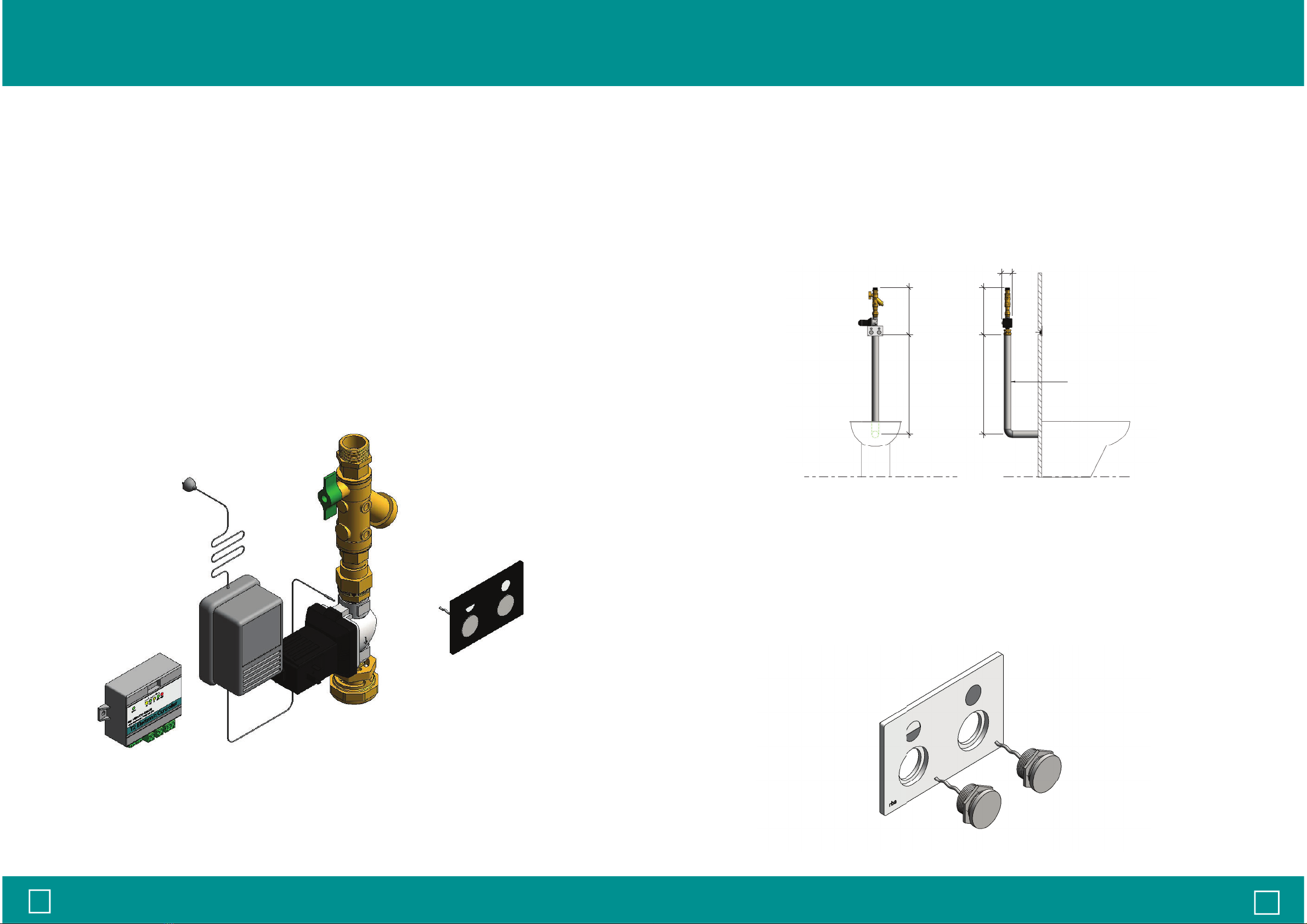
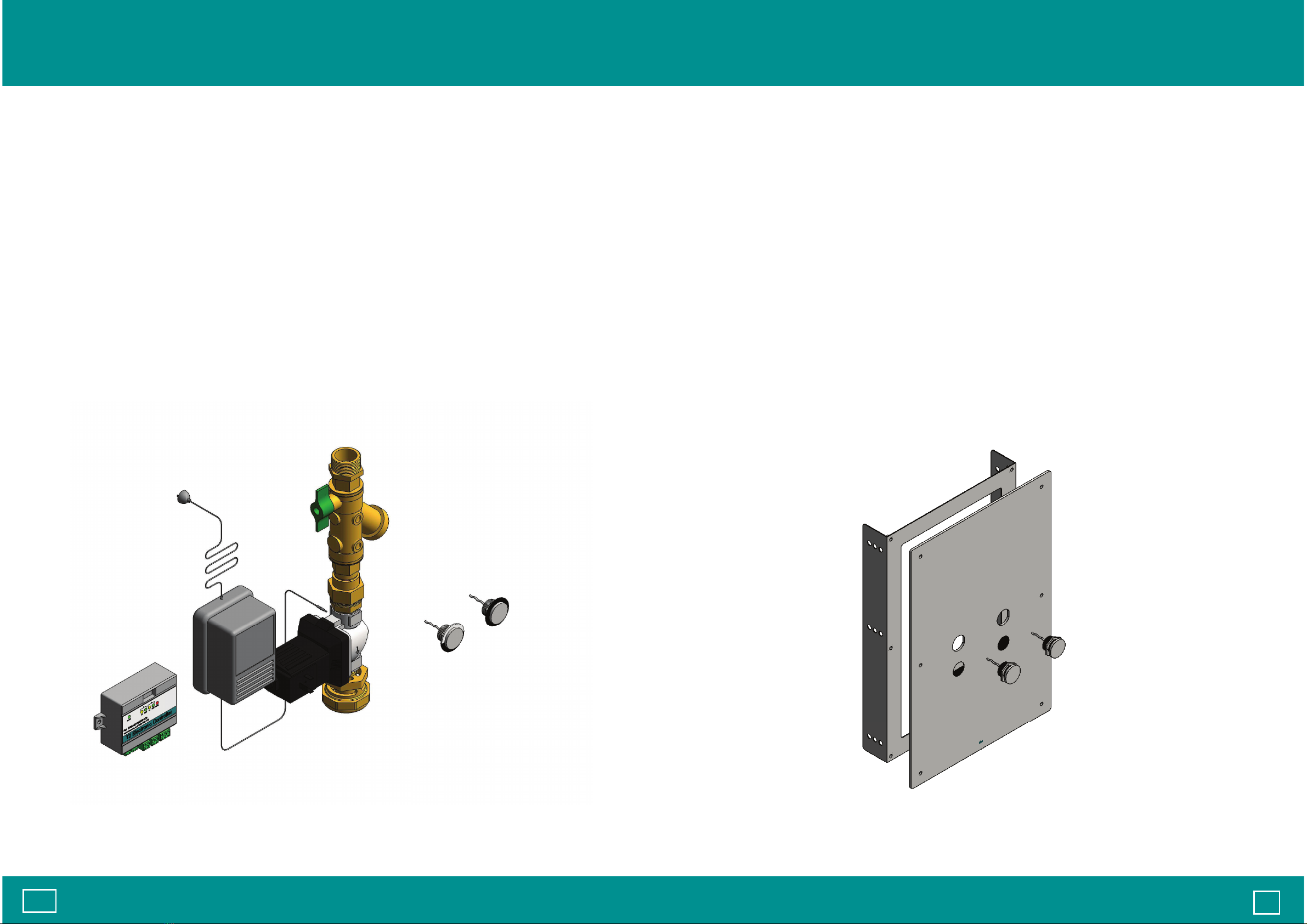
2.0 Components
RBA1882-100-001 Dual Flush Valve Incl Large Mounting Plate
5
1x RBA1882-100 'Nautilus' Flush Valve Assembly
1x RBA8012-999-003 T2 Controller [2019 version]
1x RBA8010-999-005 24V AC 2AMP Plug Pack Transformer
2x RBA8010-999-003 Piezo (3m tail)
1x RBA1880-999-001 Large Flush Valve Plate
1 x RBA1880-999-002 Recess Kit for Large Flush Valve Plate
6 x RBA1880-999-011 Counter Sink Screws (90° angle m4x25 (0.7) Pitch
Post Torx, Bit Tx15 H:3.1