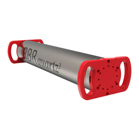
RBR RBRquartz3 Q User manual

rbr-global.com
INSTRUMENT GUIDE
Q

RBR#0008818revC
2
Table of contents
1
RBRquartz³ Q........................................................................................................ 3
2 Specifications....................................................................................................... 4
3 Hardware.............................................................................................................. 6
3.1 Opening and closing the instrument ...............................................................6
3.2
RBRquartz³ Q interface .....................................................................................7
3.3 Orientation and datum location ......................................................................9
3.4 Twist activation...............................................................................................10
3.5 Wi-Fi module ...................................................................................................11
4 General maintenance ........................................................................................ 13
4.1 Support kit.......................................................................................................13
4.2 Replacing the O-ring .......................................................................................14
4.3 Replacing the batteries...................................................................................15
4.4 Replacing the desiccant capsules ..................................................................16
4.5 Cables and connectors ...................................................................................18
4.6 Cleaning the instrument.................................................................................19
4.7 Calibrating the instrument .............................................................................19
5 Pressure sensor maintenance ........................................................................... 20
5.1 Removing the antifouling mesh assembly.....................................................20
5.2 Filling the syringe and de-gassing the buffer oil............................................21
5.3 Cleaning the buffer tube.................................................................................22
5.4 Refilling the buffer oil......................................................................................23
6 External pressure adaptor................................................................................. 26
7
Repairs ................................................................................................................ 27
8
Revision history.................................................................................................. 28

RBR#0008818revC
3
•
•
•
•
1 RBRquartz³ Q
The RBRquartz3Q integrates the Paroscientific Digiquartz® pressure sensor forbest-in-classaccuracy and low drift
performance.
Intended for long-term autonomous or realtime observations of water level, tides and waves, the RBRquartz3Q can
resolve small changes over long deployments.Flexible measurement schedules and burst sampling permit
applications for tide, wave, and sea level measurements. The RBRquartz3Q has a large memory capacity, sufficient
power for extended deployments, and USB-C or Wi-Fi download for large data files.
RBRquartz3Q
The RBRquartz3Q features:
High accuracy
Internal USB-C connector
Large memory
Quartz stability
For a detailed description of wave and tide measurements, seeRuskin User Guide: Standard Instruments3.
Temperature
sensor
Pressure
sensor

RBR#0008818revC
4
2 Specifications
Instrument
Specification Description
Storage 240 million readings
Power 8 AA-type cells
External power 4.5 to 30V
Communications Internal: USB-C; external: USB and RS-232/RS-485
Clock drift ±60 seconds/year
Depth rating Up to 260m
Housing Plastic
Diameter 100mm
Length ~510mm (with standard end-cap)
~570mm (with connectorised end-cap)
~500mm (with right-angle connectorised end-cap)
Weight(with batteries) 2.3kgin air, -0.25kgin water
.
Temperature
Specification Description
Range -5 to 35°C *
Initial accuracy ±0.002°C
Resolution 0.00005°C
Typical stability ±0.002°C/year
Time constant <30s (embedded)
*A wider temperature range is available upon request. ContactRBR for more information.
.
Pressure
Specification Description
Range 20 / 55 / 125 / 190 / 260dbar
Initial accuracy ±0.01% full scale
Resolution 100ppb (at 1Hz sampling rate)
.

RBR#0008818revC
5
Accelerometer
Specification Description
Range ±3g
Resolution <100ng
.
Power supply selection
If connected, an external power supply will be used preferentially over the internal batteriesas long as the voltage
remains 4.5V or greater. If it drops below 4.5V or complete disconnection occurs, the system automatically switches to
the internal batteries.
Clock
The instrument clock is maintained during brief disconnections. This time is usually sufficient to change batteries. If the
clock is lost, the time will revert to January 2000. In this case, check the power supply and synchronise with the
computer again.
USB-C power
The USB-C cable provides power sufficient for configuration or data download. However, the instrument requires an
internal or external power supply to perform sampling.
.
Deployment estimates (with lithium thionyl chloride cells) .
Speed Burst samples Interval Time # of samples
16Hz - Continuous ~58 days ~79.5 million
4Hz 4096 120min ~400 days ~19.5 million
1s 60 30min ~4 years ~4.5 million
.
External MCBH-6-MP connector pinout
Pin No. USB RS-232 RS-485
1Ground
2 Power +4.5 to +30V
3 N/C From the
instrument (Tx) From the
instrument (Tx-)
4 +5V Into the
instrument (Rx) Into the
instrument (Rx+)
5 D- N/C Into the
instrument (Rx-)
6 D+ N/C From the
instrument (Tx+)

RBR#0008818revC
6
1.
2.
1.
2.
1.
2.
3.
1.
2.
3.
3 Hardware
3.1 Opening and closing the instrument
.
Opening theinstrumentwith a standard end-cap
Twist the battery end-cap counterclockwise.
Once fully unscrewed, pull the end-cap away from
the housing.
.
Closing the instrument with a standard end-cap
Place the end-cap back on the instrument until
almost fully closed.
Twist the end-cap clockwise until aligned with
PAUSE. Openinstrument with a standard end-cap
Opening theinstrumentwith a connectorised end-cap
Twist the battery end-cap counterclockwise.
Once fully unscrewed, pull the end-cap away from
the housing.
Unplug the umbilical cable.
.
Closing the instrument with a connectorised end-cap
Plug the mini-display port connector into the
instrument as shown.
Twist the end-cap counterclockwise two full
rotations to unwind the umbilical cable.
Twist the end-cap clockwise back on the
instrument until aligned with PAUSE.
Open instrumentwith a connectorised end-cap
Remember to keep the O-ring clean and avoid scratching the O-ring mating surfaces. Carefully inspect the O-
ringbefore deploying the instrument.

RBR#0008818revC
7
3.2 RBRquartz³ Q interface
The RBRquartz³ Q instrument provides an internal USB-C port and, depending on the end-cap type, an
externalMCBH-6-MP connector.
.
.
USB-C connection
Remove the battery end-cap to access the USB-C port located inside the instrument body.
A USB-C desktop cable is supplied in the instrument support kit. Use this cable to download data from the instrument
to your computer.
Mini-display port
The mini-display port is located next to the USB-C port. This is the port to use for the umbilical cable from the
connectorised end-cap.
Refer to Opening and closing the instrument for details on accessing connection ports.
Refer to Specifications for the external MCBH-6-MP connector pinout diagram.
Mini-display port USB-C port

RBR#0008818revC
8
End-cap types
RBR standard instruments are compatible with three different end-caps. These end-caps are interchangeable between
instruments.
MCBH connector
.
Patch cables and underwater extension cables are sold separately. See RBR Cable Guide for details.
.
MCBH connectors
Only connectorised battery end-caps have the external MCBH-6-MP connector. Depending on your needs, they may be
wired to support the USB, RS-232, or RS-485 communication (selected at the time of order).
Connectorised end-cap Right-angle connectorised end-cap
Standard end-cap

RBR#0008818revC
9
3.3 Orientation and datum location
Vertical deployment (recommended)
RBR performs an offset adjustment with the pressure sensor facing downwards, as shown in the first image. It is
recommended to deploy the instrument vertically to match the way it was calibrated.
When deployed vertically, the datum for the pressure measurements for the RBRquartz³ Q is located at the centre of the
pressure sensor port, at the lowest surface of the instrument.
.
..
Recommended orientation:
sensors facing down
Datum location
Horizontal deployment
It is acceptable to deploy the RBRquartz³ Q horizontally if necessary. Note that, with the instrument on its side, there
will be a significant change to the datum due to the internal head values. Assess the correct offset to your preferred
datum point before deployment.
Avoid deploying the instrument vertically with the sensor facing up! Such orientation will affect performance
of the pressure sensor due to increased build-up of sediment.

RBR#0008818revC
10
3.4 Twist activation
All RBR Generation3standard instruments are equipped with twist activation as a standard feature. SeeRuskin User
Guide: Standard Instruments3.
Sampling
Twist activation allows you to start or pause the instrument without the need to connect to a computer.
When you select "Twist activation" in Ruskin, the instrument starts to sample based on the twist PAUSE/RUN position
rather than a schedule. To start sampling, first click "Enable" in Ruskin to enable logging. The status will then become
"Paused". Turn the battery end-cap to the RUN position. Theinstrument will vibrate with one long pulse and start
sampling. To pause it, turn the battery end-cap to the PAUSE position. Theinstrument will vibrate with three short
pulses to indicate it has paused logging.
.
Twist activation mode
Left: PAUSE, right: RUN
.
Wi-Fi
Twist activation allows you to connect to the instrument over the Wi-Fi when using a mobile device.
See Wi-Fi module for details.

RBR#0008818revC
11
3.5 Wi-Fi module
Instruments equipped with a Wi-Fi module have the WI-FI READY icon on the end-cap.
This module needs to be enabled at the time of purchase. ContactRBR if you have any questions about this feature.
Use the Wi-Fi module on your instrument to download the realtime data and process them while still at sea. There is no
need to open the instrument, and no need to be close to the shore as your instrument will be the router point.
When activated, the instrument will create its own SSID network which will appear under Wi-Fi networks on your
device. Your device will switch to this network and connect to the instrument. If set to Auto-download, Ruskin will start
downloading the data.
There are two ways to activate the Wi-Fi on RBR instruments: twist activation and pressure switch.
Twist activation
Activate the Wi-Fi by twisting the end-cap in either direction. The WI-Fi will stay on for 60 seconds, waiting for you to
connect. The instrument needs to be close enough for you to reach it and turn it on.
.
...
...
The Wi-Fi is disabled after 60s of inactivity. Twist the end-cap to RUN or PAUSE to re-activate the Wi-Fi.
Twisting the end-cap to the RUN or PAUSE position will activate the Wi-Fi. However, twisting to the PAUSE
position will also pause the instrument, as described above. Twist the end-cap back to RUN before continuing
with deploying your instrument.

RBR#0008818revC
12
Pressure switch
When your instrument goes underwater, the Wi-Fi will go off at the depth of 1-2m because the signal cannot get
through. However, even if the instrument stays on the surface, the Wi-Fi will go off after 60s of inactivity. Thus, there will
be no connection to the instrument while it is in the downcast phase.
During the upcast, the instrument will detect the drop in pressure and automatically switch on the Wi-Fi at about 2m
below the surface. The Wi-Fi will stay on for 60s. If your laptop is within reach during this time, Ruskin will reconnect to
the instrument and start downloading the dataset.
...
...
..
.
This feature does not apply to shallow deployments (2m or less).
The nominal Wi-Fi range is 30m for instruments in plastic housing, but it may be shorter in real life due to
challenging physical environments.
If the Wi-Fi connection is lost in the middle of the download, Ruskin will continue from where it left off next
time it detects the instrument again, appending the original RSK file.

RBR#0008818revC
13
4 General maintenance
4.1 Support kit
RBR support kit
RBR provides one support kit per every three instruments ordered. If you need more units, contact RBR.
The RBRsupport kit contains an assortment of basic accessories and spare parts, as presented below. .
RBRquartz3support kit diagram

RBR#0008818revC
14
•
•
•
4.2 Replacing the O-ring
Care for the O-ring is the single most important item of maintenance on any submersible RBR instrument. A water leak
can damage the circuit board beyond repair and cause complete data loss. Every instrument's seal depends upon its O-
ring, not the end-cap tightness. Therefore, proper O-ring maintenance is crucial.
.
.
To access the O-ring, open the instrument.
.
Inspecting the O-ring
Visually inspect the new O-ring for nicks and scratches before installing it. Pay attention to the following areas:
The surface of the O-ring itself
The mating surface on the inside of the case between the threads and the open end
The groove in the end-cap where the O-ring sits
.
.
Refer to Opening and closing the instrument for details on accessing the O-ring.
The O-ring removal tool and silicone compound are available in the support kit.
The O-ring may lose elasticity over time, even when the instrument is not deployed.RBR strongly recommends
replacing the O-ring regularly.
•
•
•
•
When handling the O-rings:
Avoid using any object that could scratch the O-ring or any of its mating surfaces.
If dirt is present in the O-ring groove, remove the O-ring as described below and thoroughly clean the
groove.
Do not return this old O-ring to the instrument! If you remove the O-ring from the instrument for any
reason, always replace it with a new one.
If the surfaces of the O-ring groove are scratched, pitted, or damaged, contact RBR for advice.
O-ring

RBR#0008818revC
15
1.
2.
3.
4.
5.
6.
7.
Replacing the O-ring
Use the plastic O-ring removal tool (included in the support kit) to remove the old O-ring from its groove.The O-
ring may need to stretch quite a bit as it is pushed off. This requires some effort, but can be done by hand.
Clean the groove thoroughly with a soft, lint-free cloth and compressed air, if necessary.
Select a new O-ring and inspect it for damage.
Lubricate with a very light film of silicone compound (included in the support kit).
Install the new O-ring by pushing it into place and popping it into its groove.
Once in place, inspect it once more for scratches and debris, and wipe away any silicone compound deposited
on the end-cap.
Close the instrument.
.
.
.
4.3 Replacing the batteries
.
RBR ships new instruments with fresh, highest capacity batteries included. Replace the batteries before each
deployment to maximise the operational time and prevent data loss.
Ruskin software estimates the remaining battery life during deployment by tracking power consumption in mAh.When
setting up your deployment on Ruskin, check "Fresh" to indicate that new batteries are installed.
If using the same batteries for a subsequent deployment, do not check "Fresh" and continue power tracking from the
previously recorded level.
See Ruskin User Guide: Standard Instruments3for more information on predicting battery life.
RBR standard instrument with batteries removed
Do not use metal screwdrivers or any other metal tool! They may scratch the O-ring groove and render the
end-cap useless.
Refer to Opening and closing the instrument for details on accessing the batteries.

RBR#0008818revC
16
1.
2.
3.
4.
5.
6.
1.
2.
3.
4.
5.
.
Replacing the batteries
Remove the battery end-cap.
Using both thumbs, press down on the "+" symbols on the battery cover and slide in the direction of the arrow.
Remove the eight old batteries from the battery carriage.
Insert eight new batteries.
Check for correct battery polarity.
Put the end-cap back on the instrument and twist clockwise until aligned with PAUSE.
.
4.4 Replacing the desiccant capsules
.
Replace desiccant capsules before each deployment.
Fresh desiccant will keep the instrument compartment dry and prevent malfunction. Water damage may occur if
condensation forms inside the instrument.
As a preventative measure, RBR recommends servicing the instrument in a cool, dry place (when possible).
.
Replacing desiccant capsules
Remove the battery end-cap.
Remove the used desiccant capsules from their sockets.
Insert fresh desiccant capsules into their sockets, face out.
Once all the capsules are secured, place the battery end-cap back in its place.
Put the end-cap back on the instrument and twist clockwise until aligned with PAUSE.
.
Always remove the batteries from your instrument during long-term storage!
Doing so will prevent internal damage due to battery leakage and/or corrosion.
Refer to Opening and closing the instrument for details on accessing the batteries.
.
Location of the desiccant capsules Direction of insertion

RBR#0008818revC
17
1.
2.
3.
4.
.
.
All instruments ship with fresh reusable desiccant capsules.They use a cobalt-free colour changing indicator dye.
Orange indicates fresh desiccant, while green indicates it is saturated (about 15% water by weight). Once exhausted,
the capsules can be replaced with new ones (available from RBR), or refreshed.
Fresh (orange) and saturated (green) desiccant capsules
Refreshing the desiccant
Follow the steps below to refresh the desiccant.
Remove the saturated silica beads from their capsule.
Place them in the oven and heat at 120°C (250°F) for about two hours.
.
.
Take the refreshed beads out of the oven and return them to the capsule.
.
.
Wait until the silica beads cool down. Once cool, the desiccant is ready to be reused.
Always remove the beads from their capsule before refreshing!
The capsule will deform if heated to 120°C.
Return the refreshed beads to the capsule immediately after reheating!
If left outside the capsule, the desiccant will trap moisture and go back to green.

RBR#0008818revC
18
•
•
•
•
•
•
•
4.5 Cables and connectors
Cable bend radius
The smallest bend radius for RBR supplied cables is 15cm.
Lubricating the connectors
Lubrication improves watertight sealing, prevents corrosion, and reduces the force required to de-mate the connector.
Use the silicone compound provided with your instrument.
Apply the silicone compound to all female connectors before every mating
Ensure each connector hole is filled with approximately 30% lubricant
Lubricatinga connector
Reducing mechanical stress
Do not pull on the cable
Hold onto the connector to pull out the cable
Disconnect by pulling straight out, not at an angle
Avoid sharp bends at the point where the cable enters the connector
Avoid angular loads on the connector

RBR#0008818revC
19
4.6 Cleaning the instrument
Clean the instrument after each extended deployment to remove deposits that may have accumulated.
.
Type Procedure Notes
General/biofouling To clean the exterior, soak in a mild
detergent, then scrub the instrument with
a soft brush.
Avoid scratching the plastic (scratches
make future cleaning more difficult).
Sensor antifouling mesh Scrub the antifouling mesh with a soft
brush. Replace the antifouling mesh if
needed.
Seeinstructions on removing the
antifouling meshfor more information.
Calcification Soak in vinegar for six hours,then scrub
the surface using a soft brush. Soaking in vinegar for more than 24 hours
may damage the O-ring and increase the
chances of a leak.
4.7 Calibrating the instrument
Factory calibration coefficients are calculated for each sensor, and the coefficients are stored on the instrument.
RBR calibrationcertificates containcalibration equations, coefficients, and residuals for each sensor. Hard copies are
provided with each shipment. RBR can replace lost or misplaced calibration certificates upon request.
RBR recommends calibrating your instrument before any critical deployment, periodically once a year, or if you suspect
the readings to be out of specifications.
Discuss your calibration requirements with RBR. In some cases, the instrument will need to be returned to RBR to have
it checked and recalibrated.
Please contactRBRfor our current calibration fees.

RBR#0008818revC
20
1.
2.
5 Pressure sensor maintenance
5.1 Removing the antifouling mesh assembly
Removing the antifouling mesh assembly may be necessary for a variety of reasons, such as cleaning the instrument
and its buffer tube, or installing the external pressure adaptor. Follow the steps below.
Remove the retaining ring using the removal tool. Hook the split in the ring at the opening and pull it out of the
recess in the sensor end-cap.
Theupper mesh insulator disk, nickel-copper mesh, and the lower mesh insulator disk will come out easily once
the retaining ring is removed.
.
Item No. Description Part image Assembled
antifouling mesh
Buffertube
interface assembly
1 Lower mesh
insulator disk
2 Nickel-copper
mesh
3 Upper mesh
insulator disk
4 Retaining ring
.
Replacement parts are available in the support kit.
Table of contents
Other RBR Measuring Instrument manuals