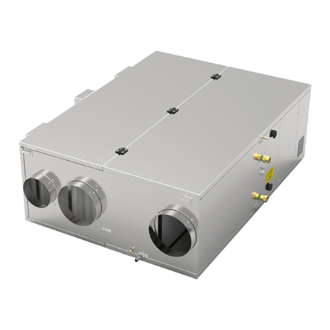
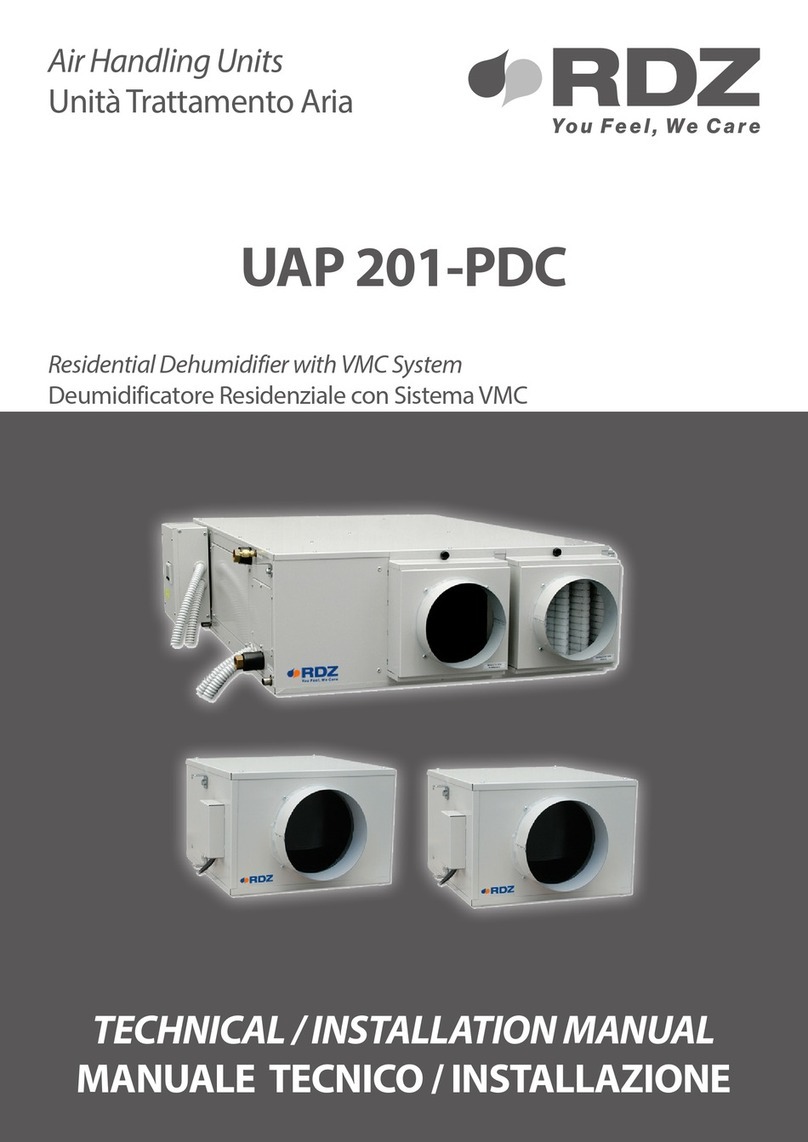
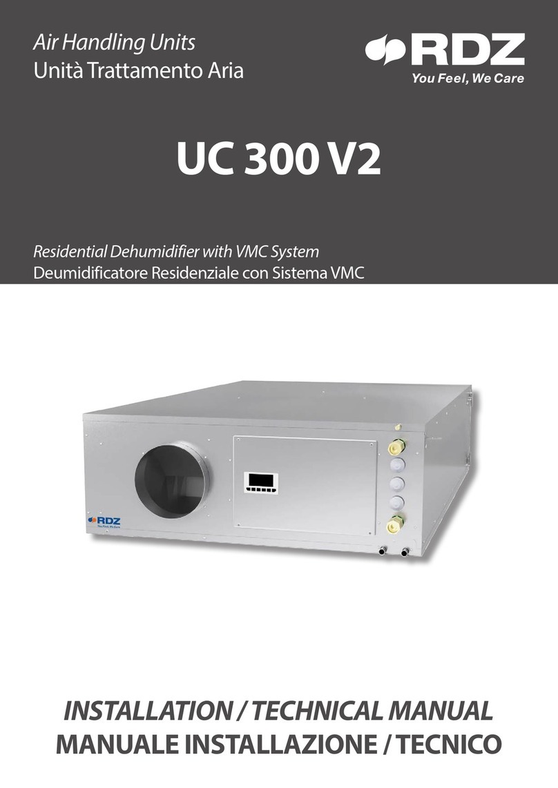
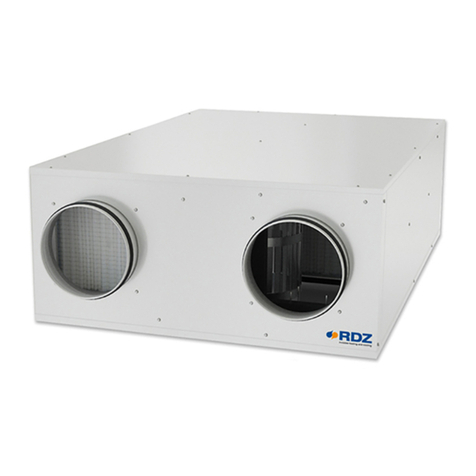
RDZ SR 701 User manual

FAG0CA015AB.01
10/2021
Air Handling Units
Unità Trattamento Aria
SR 701
INSTALLATION / TECHNICAL MANUAL
MANUALE INSTALLAZIONE / TECNICO
Unit Comfort - Commercial Units with Air Recovery
Terziario con recupero aria - Unit Comfort
rdz.it/qr?r=00000


3
Questa macchina è prevista per il controllo estivo
dell’umidità ambiente in abbinamento con impianti di
rarescamento radiante. Il suo utilizzo è raccomandato,
entro i limiti di funzionamento, in ambienti civili e/o del
settore terziario (uci, ...), per climatizzazione nalizzata
al comfort ambientale. Ogni altra applicazione diversa
DEVE essere preventivamente concordata con l’Ufficio
tecnico RDZ.
• Se dopo aver disimballato l’apparecchiatura si nota una
qualsiasi anomalia non utilizzare l’apparecchiatura e rivolgersi
ad un Centro di Assistenza autorizzato dal Costruttore.
• Alla ne dell’installazione smaltire gli imballi secondo quanto
previsto dalle normative in vigore nel Paese di utilizzo.
• Esigere solo ricambi originali: la mancata osservazione di
questa norma fa decadere la garanzia.
• Il Costruttore declina ogni responsabilità e non ritiene valida
la garanzia nei casi seguenti:
- Non vengano rispettate le avvertenze e le norme di
sicurezza sopra indicate, comprese quelle vigenti nei paesi
di installazione.
- Mancata osservanza delle indicazioni segnalate nel presente
manuale.
- Danni a persone, animali o cose, derivanti da una errata
installazione e/o uso improprio di prodotti e attrezzature.
- Inesattezze o errori di stampa e trascrizione contenuti nel
presente manuale.
• Il Costruttore, inoltre, si riserva il diritto di cessare la produzione
in qualsiasi momento e di apportare tutte le modiche che
riterrà utili o necessarie senza obbligo di preavviso.
This unit is used to control room humidity in summer
in combination with radiant cooling systems. Use is
recommended within the operation limits in residential
applications and/or commercial ones (e.g. oces). Any other
dierent use MUST be agreed in advance with RDZ technical
department.
• If, after having unpacked the equipment, any anomaly is noted,
do not use the equipment and contact an Assistance Centre
authorised by the manufacturer.
• After installation, dispose of the packaging in accordance with
the provisions of the regulations in force in the country of use.
• Use original spare parts only: disregarding this rule invalidates
the warranty.
• The manufacturer declines all responsibility and considers the
warranty invalid in the following cases:
- The aforementioned warnings and safety regulations, including
those in force in the country of installation, are not respected.
- The information given in this manual is disregarded.
- There is damage or injury to people, animals or objects, resulting
from incorrect installation and/or improper use of the products
and equipment..
- Inaccuracies or printing and transcription errors are contained
in this manual.
• The manufacturer also reserves the right to cease production at
any time and to make all the modications which it considers
useful or necessary without any obligation to give notice.
GENERAL WARNINGS | AVVERTENZE GENERALI

4
SAFETY WARNINGS | AVVERTENZE PER LA SICUREZZA
Leggere con attenzione questo libretto prima
dell’installazione e/o dell’uso dell’apparecchiatura e
conservarlo in un luogo accessibile.
La presente apparecchiatura costituisce un componenteche
fapartediinstallazionicomplesse:ècompitodell’impiantista
elettrico redigere lo schema generale dell’impianto e dei
collegamenti elettrici esterni all’apparecchiatura.
L’ufficio tecnico del Costruttore si rende disponibile
ai numeri indicati sul retro del presente libretto per
consulenze o richieste tecniche particolari.
ATTENZIONE
Tutte le operazioni di installazione e manutenzione
straordinaria descritte in questo capitolo DEVONO ESSERE
SEMPRE ESEGUITE DA PERSONALE QUALIFICATO.
Gli impianti idraulici, elettrici ed i locali di installazione
delle apparecchiature devono rispondere alle norme di
sicurezza, antinfortunistiche e antincendio in vigore nel
Paese di utilizzo.
• E’ indispensabile collegare l’apparecchiatura ad un ecace
impianto di terra e includerla in un sistema equipotenziale la
cui ecacia deve ottemperare alle norme in vigore.
• Prima di eseguire il collegamento elettrico, accertarsi che la
tensione e la frequenza riportate sulla targhetta caratteristiche
corrispondano a quelle dell’impianto d’alimentazione.
• Prima di eettuare qualsiasi intervento sull’unità, assicurarsi
di aver tolto l’alimentazione elettrica.
• Non alterare o manomettere i dispositivi di sicurezza.
• Non dirigere spruzzi d’acqua sulle parti elettriche o
sull’involucro dell’apparecchio.
• Questo apparecchio è inadatto all’utilizzo in atmosfere
esplosive o potenzialmente esplosive.
• All’atto dell’installazione o quando si debba intervenire
sull’apparecchiatura, è necessario attenersi scrupolosamente
alle norme riportate su questo manuale, osservare le
indicazioni a bordo unità e comunque applicare tutte le
precauzioni del caso.
• Le pressioni presenti nel circuito frigorifero ed i componenti
elettrici presenti possono creare situazioni rischiose durante
gli interventi di installazione e manutenzione.
• Prima di eettuare qualsiasi intervento sull’unità o prima di
accedere a parti interne, assicurarsi di aver tolto l’alimentazione
elettrica.
• All’interno dell’unità sono presenti degli organi in movimento.
Prestare attenzione quando si opera nelle loro vicinanze anche
ad alimentazione elettrica disconnessa.
• Prestare particolare attenzione alla temperatura elevata
quando si opera nelle vicinanze del compressore e della
tubazione di mandata
• Prestare particolare attenzione quando si opera in prossimità
delle batterie alettate in quanto le alette di alluminio risultano
particolarmente taglienti.
• Dopo le operazioni di manutenzione richiudere sempre
l’unità tramite le apposite pannellature, ssandole con le viti
di serraggio.
Read this manual carefully before installing and/or using the
equipment and keep it in an accessible place.
This equipment constitutes a component which is part of
complex installations: it is the responsibility of the electrical
installer to draw up the general diagram of the system and
the electrical connections outside the equipment.
The manufacturer’s technical oce can be contacted on the
numbers shown on the back of this manual for queries or
special technical requests.
CAUTION
All the installatione and extraordinary maintenance
operations described in this chapter MUST ALWAYS BE
CARRIED OUT BY QUALIFIED PERSONNEL.
The hydraulic and electrical systems and the places where
the equipment is tobe installed must complywith the safety,
accident prevention and re prevention standards in force
in the country of use.
• It is essential to connect the equipment to an eective earthing
system and include it in an equipotential system whose
eectiveness.
• Before making the electrical connection, ensure that the voltage
and frequency shown on the data plate correspond to those of
the power supply system.
• Before performing any intervention on the unit, ensure that the
electrical power supply has been disconnected.
• Do not alter or tamper with the safety devices.
• Do not direct jets of water onto the electrical parts or onto the
equipment packaging.
• This appliance is not suitable for use in explosive or potentially
explosive atmospheres.
• During installation or when it is necessary to intervene on the
equipment, it isnecessary to followthe rules shownin this manual
very carefully, respect the information on board the unit and
alwayss take all the appropriate precautions.
• The pressure of the refrigerating circuit and the electrical
components may create dangerous situations during installation
and maintenance interventions.
• Before performing any intervention on the unit or before
accessing internal parts, ensure that the electrical power supply
has been disconnected.
• There are moving components inside the unit. Take particular
care when operating in their vicinity, even when the electrical
power supply is disconnected.
• One part of the compressor casing and the delivery piping are
at a high temperature. Take particular care when operating in
their vicinity.
• Take particular care when operating in proximity to the nned
coils as the aluminium ns are particularly sharp.
• After maintenance operations, always close the unit using the
special panelling, securing it using xing screws.
5
In base a quanto previsto dalle seguenti direttive
europee 2011/65/UE, 2012/19/UE e 2003/108/
CE, relative alla riduzione dell’uso di sostanze
pericolose nelle apparecchiature elettriche ed
elettroniche, nonché allo smaltimento dei riuti.
Il simbolo del cassonetto barrato riportato sull’apparecchiatura
indica che il prodotto alla ne della propria vita utile deve essere
raccolto separatamente dagli altri riuti.
Al termine del ciclo di vita dell’unità, in previsione di una sua
rimozione, andranno seguiti una serie di accorgimenti:
Il gas refrigerante in essa contenuto va recuperato da parte di
personale specializzato ed inviato ai centri di raccolta;
L’olio di lubricazione dei compressori va anch’esso recuperato
ed inviato ai centri di raccolta;
La struttura ed i vari componenti, se inutilizzabili, vanno
demoliti e suddivisi a seconda del loro genere merceologico: ciò
vale in particolare per il rame e l’alluminio presenti in discreta
quantità nella macchina.
Tutto ciò per agevolare i centri di raccolta, smaltimento e
riciclaggio e per ridurre al minimo l’impatto ambientale che
tale operazione richiede.
L’adeguata raccolta differenziata per l’avvio successivo
dell’apparecchiatura dismessa al riciclaggio, al trattamento e allo
smaltimento ambientale compatibile contribuisce ad evitare
possibili eetti negativi sull’ambiente e sulla salute e favorisce
il riciclo dei materiali di cui è composta l’apparecchiatura.
Lo smaltimento abusivo del prodotto da parte dell’utente
comporta l’applicazione delle sanzioni previste dalla vigente
normativa in materia.
In accordance with the provisions of the following
European directives 2011/65/EU, 2012/19/EU and
2003/108/EC, regarding reducing the use of
hazardous substances in electrical and electronic
equipment, in addition to waste disposal.
The crossed-out rubbish bin symbol shown on the equipment
indicates that, at the end of its useful life, the product must be
collected separately from other waste.
At the end of the life cycle of the unit, before its removal, the
following precautions must be taken:
The refrigerating gas contained within it must be recovered
separately by specialised personnel and sent to collection centres;
The lubrication oil for the compressors must also be recovered and
sent to collection centres;
The structure and the various components, if they can no longer
be used, must be demolished and divided up according to the
type of product: this is particularly important for the copper and
aluminium components, which are included in the machine in
moderate quantities.
All this helps collection, disposal and recycling centres reduce the
environmental impact this operation requires.
Appropriate separate waste collection for subsequent sending of
the disused equipment for recycling, treatment and compatible
environmental disposal contributes to preventing possible
negative eects on the environment and favours recycling of the
materials of which the equipment is composed.
The abusive disposal of the product by the user leads to the
application of the penalties envisaged by current regulations
regarding the matter.
DISPOSAL | SMALTIMENTO

6
INDEX | INDICE
Description Descrizione Pag
GENERAL WARNINGS AVVERTENZE GENERALI 3
SAFETY WARNINGS AVVERTENZE PER LA SICUREZZA 4
DISPOSAL SMALTIMENTO 5
PRELIMINARY OPERATIONS OPERAZIONI PRELIMINARI 7
1GENERAL OVERVIEW PANORAMICA GENERALE 8
1.1 Description Descrizione 8
1.2 Machine Components Componenti Apparecchiatura 8
1.3 Package Content Contenuto Imballo 9
1.4 Complements Complementi 9
1.5 Unit circuit description Descrizione circuiti macchina 10
1.6 Internal component description Descrizione componenti interni 10
2INSTALLATION INSTALLAZIONE 11
2.1 Distribution example Esempio di distribuzione 11
2.2 Positioning and xing to the ceiling Posizionamento e ssaggio a sotto 12
2.3 Hydraulic Connections Collegamenti Idraulici 16
2.4 Electrical Connections Collegamenti Elettrici 20
3START-UP AND TESTING AVVIAMENTO E COLLAUDO 23
3.1 Inow fan setting on ventilation mode Set ventilatore immissione in rinnovo 23
3.2 Discharge fan setting on ventilation mode Set ventilatore espulsione in rinnovo 24
4USE UTILIZZO 24
4.1 Recirculation mode Funzionamento ricircolo 25
4.2 Fresh air ventilation mode Funzionamento rinnovo 26
5MAINTENANCE MANUTENZIONE 27
5.1 Ordinary Maintenance Manutenzione Ordinaria 27
5.2 Extraordinary Maintenance Manutenzione Straordinaria 28
6TECHNICAL DATA AND PERFORMANCE DATI TECNICI E PRESTAZIONI 29
6.1 Dimensions and Technical data Dimensioni e Dati tecnici 29
6.2 Operating limits Limiti di funzionamento 30
6.3 Performance Prestazioni 30
6.4 Recovery performance Prestazioni recuperatore 32
6.5 Available pressures to the intake outlet Prevalenze utili alla bocchetta di immissione 33
6.6 Available pressures to the air discharge outlet Prevalenze utili alla bocchetta di espulsione 33
7WIRING DIAGRAM SCHEMA ELETTRICO 34

7
1
5
OK! RDZ
6
2a 2b
3b
3a
entro 8 giorni
within 8 days
OK!
4
ISPEZIONE, TRASPORTO E DISIMBALLO
All’atto del ricevimento vericare immediatamente l’integrità
dell’imballo: la macchina ha lasciato la fabbrica in perfetto stato,
eventuali danni dovranno essere immediatamente contestati
al trasportatore ed annotati sul Foglio di Consegna prima di
contrormarlo.
Il Cliente, entro 8 giorni, deve avvisare il Costruttore sull’entità
e la tipologia dei danni rilevati compilando un rapporto scritto:
riportare sempre anche il numero di matricola rilevabile dalla
targhetta posta a bordo macchina.
L’imballo dell’unità deve essere
rimosso con cura evitando di arrecare
possibili danni alla macchina.
I materiali che costituiscono l’imballo
sono di natura diversa: legno,
cartone, nylon, ecc.
Conservarli separatamente e
consegnarli per lo smaltimento o
l’eventuale riciclaggio, alle aziende
preposte allo scopo e ridurne così
l’impatto ambientale.
The unit packaging must be
removed with care, ensuring that
the machine is not damaged.
The materials which make up the
packaging are different: wood,
cardboard, nylon etc.
Store them separately and deliver
them for disposal or, where
appropriate, recycling, to the
relevant companies, thus reducing
the environmental impact.
TESTING, TRANSPORT AND UNPACKAGING
Upon receipt, check immediately that the packaging is intact:
the machine has left the factory in perfect working order and any
damage must be notied to the carrier immediately and noted on
the Delivery Sheet before it is countersigned.
Within 8 days, the customer must notify the manufacturer of the
extent and type of the damage noted, making a written report:
always take note of the serial number which can be found on the
plate axed to the machine.
PRELIMINARY OPERATIONS | OPERAZIONI PRELIMINARI

8
D
I
B
C
E
H
G
F
A
Wiring Box
Quadro Elettrico
Ø 14 mm Condensation Drain
Scarico Condensa Ø 14 mm
AIR FILTERS - FILTRI ARIA
e(PM10) min ≤50 %
Hairs - Peli, capelli
ISO
coarse
coarse
50%
coarse
50%
INGRESSO ARIA ESTERNA
FRESH AIR INLET
ESPULSIONE ARIA
EXHAUST AIR
ESTRAZIONE ARIA VIZIATA
STALE AIR EXTRACTION
IMMISSIONE ARIA
SUPPLY AIR
RICIRCOLO ARIA
RECIRCULATION AIR
Table A - Machine Components | Tabella A - Componenti apparecchiatura
Rif. Descriptions Descrizione
ARoom intake double damper recirculation/renewal Serranda doppia ripresa ambiente ricircolo/rinnovo
BRoom air intake lter Filtro ripresa aria ambienti
CHeat recovery Recuperatore di calore
DOutside air intake lter Filtro ripresa aria esterna
EOutside air intake Serranda ripresa aria esterna
FOutput fan Ventilatore espulsione
GCondensation drain (with upside-down installation) Scarico condensa (se montato capovolto)
HCondensation drain Scarico condensa
ISwitchboard Quadro elettrico
Recuperatore di calore a ussi incrociati da abbinare esclusivamente
al deumidicatore DA 701.
È dotato di ventilatore ad alta ecienza sul lato espulsione e serrande
motorizzate per la gestione del rinnovo. Il usso d’aria esterna e di
ricircolo è demandato al ventilatore del deumidicatore DA.
• Portata d’aria nominale di 750 m³/h
• Prevalenza utile ventilatore di espulsione 285 Pa
• Prevalenza utile ventilatore di immissione 210 Pa
• Ecienza del recuperatore: 59,4 %
• 1 sifone obbligatorio.
SR 701 cross-flow heat exchanger shall be combined with DA 701
dehumidier.
It is equipped with a high-eciency fan in the exhaust duct, while fresh
air intake and air recirculation are managed by the fan in the DA 701 unit.
• Nominal air ow-rate 750 m³/h
• Available pressure for the exhaust fan 285 Pa
• Available pressure for the supply fan 210 Pa
• Heat exchanger eciency 59,4 %.
• It is mandatory to use 1 condensate drain kit.
1GENERAL OVERVIEW | PANORAMICA GENERALE
1.1 DESCRIPTION | DESCRIZIONE
1.2 MACHINE COMPONENTS | COMPONENTI APPARECCHIATURA

9
1.3 PACKAGE CONTENT | CONTENUTO IMBALLO
Rif. Descriptions Descrizione
1
SR 701 SR 701
2
Installation / Technical Manual Manuale Installazione / Tecnico
2
1
CONDENSATE DRAIN - SCARICHI CONDENSA Cod.
SF-M 13 Condensate drain kit consisting of a siphon with silicone membrane, hose and tting, to be
used in combination with RDZ air handling units.
SF-M 13 Kit di scarico condensa composto da sifone con membrana in silicone, tubo e raccordo, da
utilizzare in abbinamento alle unità di trattamento dell’aria RDZ.
3600401
SF-P Condensate drain kit with casing, designed for wall installation. It can be used in combination
with RDZ air handling units, and it is suitable for Ø 20-32 mm piping. The external shell can be adjusted
considering the thickness of the wall. Washable Internal Cartridge.
SF-P Sifone per scarico condensa completo di involucro previsto per l’incasso a muro da utilizzare
in abbinamento alle unità di trattamento dell’aria RDZ. Predisposto per il collegamento a tubazioni
Ø 20-32 mm. Completo di rivestimento esterno regolabile in base alla profondità della parete.
Cartuccia lavabile.
7045502
1.4 COMPLEMENTS | COMPLEMENTI
E’ obbligatoria l’installazione di nr. 1 Scarico Condensa
scegliendo, in base alle necessità, fra quelli proposti.
The installation of no. 1 Condensate drain choosing, according to
the needs, among those proposed.
OBBLIGATORIMANDATORY
RICAMBIREPLACEMENTS
AIR FILTERS KIT - KIT FILTRI ARIA Cod.
SR 701 FILTERS KIT
Kit for complete replacement of unit lters containing:
• 1 ISO Coarse 50% lter - Stale air extraction
• 1 ISO Coarse 50% lter - Fresh air inlet
KIT FILTRO SR 701
Kit per la sostituzione completa dei ltri dell’unità contenente:
• 1 ltro ISO Coarse 50% - Estrazione aria viziata
• 1 ltro ISO Coarse 50% - Ingresso aria esterna
7044190

10
1.5 UNIT CIRCUIT DESCRIPTION | DESCRIZIONE CIRCUITI MACCHINA
Rif. Descriptions Descrizione
1Room suction lter Filtro aspirazione ambienti
2Outdoor air suction lter Filtro aspirazione aria esterna
3Recirculation/Exhaust damper Serranda commutazione ricircolo/espulsione
4Fresh air ventilation damper Serranda rinnovo
5Exhaust fan Ventilatore espulsione
6aAir recirculation ow a Flusso aria ricircolo
bAir exhaust ow b Flusso aria espulsione
7Fresh air ventilation ow Flusso aria rinnovo
8Treatment ow Flusso trattamento
Circuits of the unit
Circuiti machina
DA 701
110 l/h - 15 °C750 l/h - 15 °C
SR 701
5
3
1
42
6a6b
78
COMPONENTI
Tabella E - Componenti
Componente Descrizione
Recuperatore
di calore
Recuperatore di calore a ussi incrociati.
Ventilatore Di tipo centrifugo a doppia aspirazione con
motore direttamente accoppiato
Filtro Filtro con materiale ltrante in bra sintetica,
classe ISO Coarse 50%
Serrande Serrande motorizzate ON-OFF per la
regolazione dei flussi dell’aria (rinnovo/
ricircolo)
COMPONENTS
Tabella E - Components
Component Description
Heat recovery
unit
Cross-ow heat recovery unit.
Fan Centrifugal version with double suction and
combined direct motor
Filter Filter made of synthetic bre,
class ISO Coarse 50%
Dampers ON-OFF motorized dampers to control air
ows (renewal/recirculation)
1.6 INTERNAL COMPONENTS DESCRIPTION | DESCRIZIONE COMPONENTI INTERNI

11
2INSTALLATION - INSTALLAZIONE
2.1 DISTRIBUTION EXAMPLE | ESEMPIO DI DISTRIBUZIONE

12
2.2 POSITIONING AND FIXING TO THE CEILING | POSIZIONAMENTO E FISSAGGIO A SOFFITTO
CAUTION
Installation and maintenancemust be carried outby qualied
personnel only. Throughout installation, make sure that the
equipment is not connected to the electrical mains.
It shall be installed only inside the building.
ATTENZIONE
L’installazione e la manutenzione vanno eseguiti solo
da personale qualicato. Durante tutte le procedure di
installazione, assicurarsi che l’apparecchiatura non sia
collegata alla rete elettrica.
L’installazione deve essere eettuata solo all’interno
degli edici
Positioning indications
Indicazioni di posizionamento
OK!
OK!
MAX 95% MAX 30°C
OK!
OK!
min.
30 cm
min.
60 cm
Minimum space allowanceses
Distanze minime di rispetto
no constraint
nessun vincolo
min. 60 cm min. 60 cm

13
[mm]
ø8mm
2
Remove the lter from DA 701
Estrarre ltro da DA 701
Possible installation with DA 701
Installazioni possibili al DA 701
690
634
300
1
AB
OFF!
Spento!
3
33
4
5

14
Fixing to ceiling
Fissaggio a sotto
Washer
Rondella
Rubber mounts
Gommino antivibrante
11

15
Fixing to ceiling
Fissaggio a sotto
min.
40 cm
min.
20 cm
min.
60 cm min.
60 cm
Trap door
Botola d’ispezione
SR DA

16
2.3 HYDRAULIC CONNECTIONS | COLLEGAMENTI IDRAULICI
COLLEGAMENTO VALVOLA H2O OBBLIGATORIA
ATTENZIONE: è obbligatorio installare la valvola nel
caso di abbinamento DA+SR.
ATTENZIONE: la valvola va installata solo nella linea
di pre-trattamento e non deve intercettare in nessun
modo la linea di post-trattamento.
NECESSARY H2O VALVE CONNECTION
WARNING: The use of the valve is compulsory in case
of combination between DA and SR units.
WARNING: The optional valve must be installed in the
pre-treatment line only and should not interfere with
the post-treatment line.
WIRING DIAGRAM FOR COMPLETE HYDRAULIC CONNECTION
SCHEMA DI COLLEGAMENTO IDRAULICO COMPLETO
GND - BLACK/ NERO
Y- GREY / GRIGIO
+24 V - RED / ROSSO
69100 0 7 8
AB A
B
Kv
4,03
SCHEMA IDRAULICO CON VALVOLA MODULANTE
HYDRAULIC DIAGRAM WITH MODULATING VALVE
IN (B)
OUT (A)
IN (D)
(E)
OUT (C)
Tank
Accumulo
Drain
Scarico
DA 701
PRECOND
AB A
B
KEY / LEGENDA
Circulation pump
Circolatore
Flow rate lockshield
Detentore di regolazione portata
Condensation drain kit
Kit scarico condensa
On/O Valve
Valvole di intercettazione
Non-return valve
Valvola di non ritorno
Flowmeter
Misuratore di portata
Recommended components
Componenti consigliati
Modulating valve for DA unit
Valvola modulante per DA Kv 4,03

17
INSTALLAZIONE SCARICHI CONDENSACONDENSATION DRAIN INSTALLATION
Lo scarico condensa e le tubazioni di ingresso e
uscita devono rispondere alle norme e leggi vigenti
nel paese di utilizzo.
Il sistema di scarico (attacco portagomma Ø 14 mm) deve
prevedere un adeguato sifone, dimensionato per una portata
di 15 l/h e avente una pendenza minima, sia per consentire il
deusso della condensa in condizioni di possibile depressione,
sia per evitare l’ingresso di odori indesiderati.
È necessario realizzare il sifone sulla linea di scarico
utilizzando e scegliendo, in base alle esigenze, fra i
kit di scarico condensa RDZ disponibili (SF-P / SF-M
13). Rispettare, in base al modello scelto, le
indicazioni di installazione riportare di seguito.
• Il sifone non deve esser posizionato necessariamente sotto la
macchina ma può essere spostato lateralmente e posizionato
ad una quota comunque inferiore al raccordo di scarico
dell’unità.
• Il sifone deve potersi disconnettere facilmente dal punto di
scarico sulla macchina e/o sull’accessorio al ne di agevolare
eventuali manutenzioni. Adescare il sifone prima della messa
in servizio.
• Assicurarsi che il tubo per il deusso della condensa non
solleciti l’attacco di scarico dell’unità.
• Lo scarico condensa dovrà essere adeguatamente supportato
e correttamente isolato se quest’ultimo passa attraverso
spazi non riscaldati (esempio verande esterne) per prevenire
il congelamento.
• Lo scarico condensa del SR dovrà essere realizzato
totalmente indipendente dallo scarico del DA
The condensation drain and the inlet andoutlet pipes
must comply with the standards and laws in force in
the country of use.
The condensate pipeline (hose connector Ø 14 mm) shall be
provided with a syphon, considering a flowrate of 15 l/h and
minimum inclination, both to win the possible air underpressure
at outlet and to avoid the entry of bad smells.
It is necessary to make the siphons on drain line using
and choosing, as required, from the available RDZ
condensate drain kits (SF-P / SF-M 13). According to
themodel chosen,respect theinstallation instructions
given below.
• Syphon shall be sized according to instructions on below gure.
It must not necessarily be positioned under the machine, but
can be moved laterally and always positioned lower than the
tting unit drain.
• It shall be possible to easily disconnect the syphon on the unit
and/or on the accessory in order to facilitate possible services;
prime syphon before starting up.
• Check that pipeline doesn’t stress condensate outlet connection.
• The condensate drain system should be adequately supported
and suitably insulated if it passes through unheated spaces and
voids (e.g. loft spaces) to prevent freezing.
• Condensation drain of SR can be carried out independently
from DA drain
KIT OBBLIGATORI PER SCARICO CONDENSAOBLIGATORY KIT FOR CONDENSATE DRAIN
min. 20 cm
max. 350 cm
≥ 2 %
≥ 8 cm
max. 20 cm
≥ 9 %
SF-P SF-M 13
A
B

18
INSTALLATION INSTALLAZIONE
SF-P
A
min. 20 cm
max. 350 cm
≥ 2 %
DN32
1. 3.
Ø20-32mm
4.
2.
SF-P Cod.
Condensate drain kit with casing, designed for wall installation. It can be used in combination with RDZ
air handling units, and it is suitable for Ø 20-32 mm piping. The external shell can be adjusted considering
the thickness of the wall. Washable Internal Cartridge. For information see the dedicated technical sheet.
Sifone per scarico condensa completo di involucro previsto per l’incasso a muro da utilizzare in
abbinamento alle unità di trattamento dell’aria RDZ. Predisposto per il collegamento a tubazioni
Ø 20-32 mm. Completo di rivestimento esterno regolabile in base alla profondità della parete.
Cartuccia lavabile. Per informazioni consulta la scheda tecnica dedicata.
7045502

19
NOTE AGGIUNTIVE PER INSTALLAZIONE KIT SCARICO RDZ
• Inserire delicatamente il sifone sul tubo di scarico usando
l’apposito adattatore fornito.
Importante: Controllare che le frecce stampate sul sifone
puntino in direzione del usso dell’acqua. Per garantire
che il sifone funzioni correttamente, fare passare un po’
d’acqua da un rubinetto attraverso il sifone in direzione
delle frecce. Delicatamente far uire l’acqua nel sifone
attraverso l’imboccatura della curva.
• Utilizzare una
tubazione idonea (non fornita)
per completare
il sistema di scarico condensa.
Importante
: Lo scarico dovrà avere un dislivello minimo di
8 cm e una pendenza approssimativamente del 9% (9 cm
di dislivello ogni 100cm di lunghezza) rispetto allo scarico
principale più vicino.
ADDITIONAL NOTES FOR RDZ DRAIN KIT INSTALLATION
• Gently insert the siphon on the exhaust pipe using the provided
adapter.
Important: check that the arrows printed on the siphon are
pointing in the direction of the water ow.
Ensure that the waterless trap operates correctly by running
a trickle of water from a tap through the trap in the direction
of the arrows. Gently ow the water in the siphon through
the mouth of the curve.
• Use suitable tubing (not supplied) to complete the condensate
drain-system.
Important:thedrainmusthavea minimumheight dierence
of 8 cm and incorporate a continuous fall of approximately
9% (9 cm in every 100cm) to the nearest waste water
network.
Scarico NON in salita!
Discharge NOT in ascent!
Sifone SR (SF-M 13)
SR Siphon
(SF-M 13)
Sifone DA (SF-M 20)
DA Siphon
(SF-M 20)
F
E
SF-M 13
B
≥9%
≥ 8 cm
OK
max. 20 cm
SF-M 13 Cod.
Condensate drain kit consisting of a siphon with silicone membrane, hose and tting, to be used in
combination with RDZ air handling units.
Kit di scarico condensa composto da sifone con membrana in silicone, tubo e raccordo, da utilizzare
in abbinamento alle unità di trattamento dell’aria RDZ.
3600401

20
Il recuperatore deve essere collegato ad una presa di
corrente sezionata provvista di terra. L’impianto elettrico di
alimentazione deve essere protetto contro i sovraccarichi, i
cortocircuiti, i contatti diretti ed indiretti, conformemente
alle leggi e norme vigenti nel paese di utilizzo. Gli interventi
elettrici devono essere eettuati da personale qualicato.
La linea elettrica di alimentazione deve essere
protetta da un interruttore dierenziale magnetotermico.
Verificare che la tensione di alimentazione
corrisponda ai dati nominali dell’unità (tensione, numero
di fasi, frequenza) riportati in questo manuale e sulla
targhetta a bordo macchina. L’allacciamento di potenza
avviene tramite cavo bipolare più terra. La tensione di
alimentazione non deve subire variazioni superiori a ±5%.
Il funzionamento deve avvenire entro i valori sopra
citati: in caso contrario la garanzia viene a decadere
immediatamente e ci sono rischi elettrici per le persone e
il prodotto.
APERTURA SPORTELLO
The heat exchanger must be connected to a
disconnected, earthed power socket. The electrical system
must be protected against overloads, short circuits and
direct and indirect contacts and comply with the laws
and regulations in force in the country of use. Electrical
interventions must be performed by qualied personnel.
The electrical powerlinemust beprotectedbyaresidual
current device.
Check that the power supply voltage corresponds to
the rated unit data (voltage, number of phases, frequency)
shown on this manual and on the plate on the machine. The
power connection takes place through a bipolar cable plus
earth. The power supply voltage is not subject to variations
greater than ±5%.
Operation must take place within the aforementioned
values: if this is not the case, the warranty is invalidated
immediately, and there are electrical risks for people and
for the product.
DOOR OPENING
2
1
2.4 ELECTRICAL CONNECTIONS | COLLEGAMENTI ELETTRICI
Table of contents
Other RDZ Air Handler manuals

RDZ
RDZ 1057230 Instruction Manual

RDZ
RDZ RNW 404-CS Technical document

RDZ
RDZ RNW 411 CoRe User manual

RDZ
RDZ BA-P User manual

RDZ
RDZ WHR 61 Technical document

RDZ
RDZ SR 2001 User manual

RDZ
RDZ WHR 400 User manual

RDZ
RDZ CHR 100 Technical document

RDZ
RDZ RNW 600 CS User manual

RDZ
RDZ RNW 204-I Technical document

RDZ
RDZ CHR 120-FC/S Technical document

RDZ
RDZ RNW 214 CoRe Technical document

RDZ
RDZ CHR 400 CoRe User manual

RDZ
RDZ RNW 204-I Assembly instructions

RDZ
RDZ SILVENT HRX2D Technical document

RDZ
RDZ SR 1001 User manual

RDZ
RDZ DWF 400 User manual

RDZ
RDZ WHR 60 User manual

RDZ
RDZ RNW 214-I Technical document

RDZ
RDZ RNW 508-CS Technical document