manuals.online logo
Brands
  1. Home
  2. •
  3. Brands
  4. •
  5. RDZ
  6. •
  7. Air Handler
  8. •
  9. RDZ WHRI 150 User manual

RDZ WHRI 150 User manual

FAF0CE002AB.00
01/2022
Air Handling Units
Unità Trattamento Aria
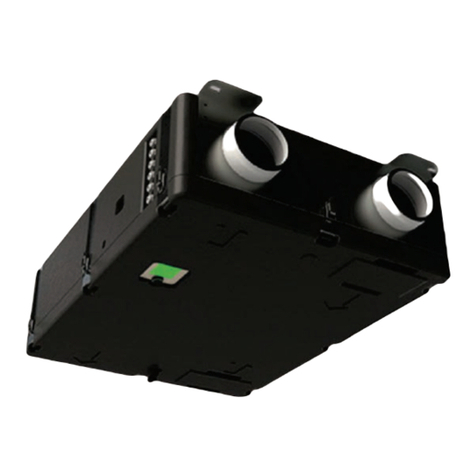
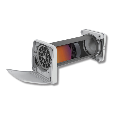
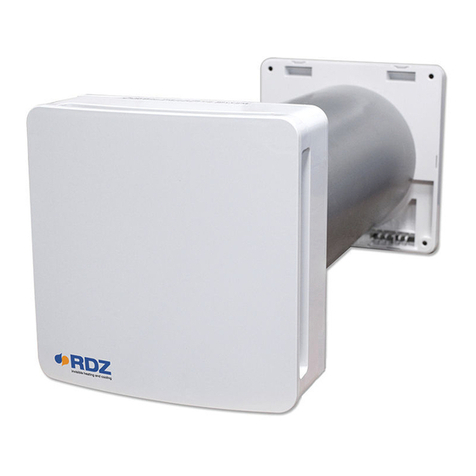
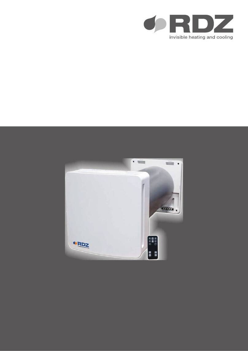
WHRI 150/220
COMPONENTI DA INCASSO
INSTALLATION MANUAL
MANUALE INSTALLAZIONE
Residential Two-Way Ventilation Unit
Unità di Ventilazione Bidirezionale residenziale
rdz.it/qr?r=00000
33
• E’ indispensabile collegare l’apparecchiatura ad un ecace
impianto di terra e includerla in un sistema equipotenziale la
cui ecacia deve ottemperare alle norme in vigore.
• Prima di eseguire il collegamento elettrico, accertarsi che la
tensione e la frequenza riportate sulla targhetta caratteristiche
corrispondano a quelle dell’impianto d’alimentazione.
• Prima di eettuare qualsiasi intervento sull’unità, assicurarsi
di aver tolto l’alimentazione elettrica.
• Non alterare o manomettere i dispositivi di sicurezza.
• Non dirigere spruzzi d’acqua sulle parti elettriche o
sull’involucro dell’apparecchio.
• Questo apparecchio è inadatto all’utilizzo in atmosfere
esplosive o potenzialmente esplosive.
• All’atto dell’installazione o quando si debba intervenire
sull’apparecchiatura, è necessario attenersi scrupolosamente
alle norme riportate su questo manuale, osservare le
indicazioni a bordo unità e comunque applicare tutte le
precauzioni del caso.
• Le pressioni presenti nel circuito frigorifero ed i componenti
elettrici presenti possono creare situazioni rischiose durante
gli interventi di installazione e manutenzione.
• It is essential to connect the equipment to an eective earthing
system and include it in an equipotential system whose
eectiveness.
• Before making the electrical connection, ensure that the voltage
and frequency shown on the data plate correspond to those of
the power supply system.
• Before performing any intervention on the unit, ensure that the
electrical power supply has been disconnected.
• Do not alter or tamper with the safety devices.
• Do not direct jets of water onto the electrical parts or onto the
equipment packaging.
• This appliance is not suitable for use in explosive or potentially
explosive atmospheres.
• During installation or when it is necessary to intervene on the
equipment, it is necessary to follow the rules shown in this manual
very carefully, respect the information on board the unit and
alwayss take all the appropriate precautions.
• The pressure of the refrigerating circuit and the electrical
components may create dangerous situations during installation
and maintenance interventions.
Leggere con attenzione questo libretto prima
dell’installazione e/o dell’uso dell’apparecchiatura e
conservarlo in un luogo accessibile.
La presente apparecchiatura costituisce un componente che
fa parte diinstallazionicomplesse: ècompito dell’impiantista
elettrico redigere lo schema generale dell’impianto e dei
collegamenti elettrici esterni all’apparecchiatura.
L’ufficio tecnico del Costruttore si rende disponibile
ai numeri indicati sul retro del presente libretto per
consulenze o richieste tecniche particolari.
ATTENZIONE
L’installazione e la manutenzione vanno eseguiti solo da
personale qualicato.
Gli impianti idraulici, elettrici ed i locali di installazione
delle apparecchiature devono rispondere alle norme di
sicurezza, antinfortunistiche e antincendio in vigore nel
Paese di utilizzo.
Read this manual carefully before installing and/or using the
equipment and keep it in an accessible place.
This equipment constitutes a component which is part of
complex installations: it is the responsibility of the electrical
installer to draw up the general diagram of the system and
the electrical connections outside the equipment.
The manufacturer’s technical oce can be contacted on the
numbers shown on the back of this manual for queries or
special technical requests.
CAUTION
Installation and maintenance must only be carried out by
qualied personnel.
The hydraulic and electrical systems and the places where
the equipment is to be installed must comply with the safety,
accident prevention and re prevention standards in force
in the country of use.
SAFETY WARNINGS - AVVERTENZE PER LA SICUREZZA
44
In base a quanto previsto dalle seguenti direttive
europee 2011/65/UE, 2012/19/UE e 2003/108/
CE, relative alla riduzione dell’uso di sostanze
pericolose nelle apparecchiature elettriche ed
elettroniche, nonché allo smaltimento dei riuti.
Il simbolo del cassonetto barrato riportato sull’apparecchiatura
indica che il prodotto alla ne della propria vita utile deve essere
raccolto separatamente dagli altri riuti.
L’utente dovrà, pertanto, conferire l’apparecchiatura giunta
a ne vita agli idonei centri di raccolta dierenziata dei riuti
elettronici ed elettrotecnici, oppure riconsegnarla al rivenditore
che, a fronte di acquisto di apparecchio equivalente, è tenuto
al ritiro gratuito del prodotto da smaltire.
L’adeguata raccolta differenziata per l’avvio successivo
dell’apparecchiatura dismessa al riciclaggio, al trattamento e allo
smaltimento ambientale compatibile contribuisce ad evitare
possibili eetti negativi sull’ambiente e sulla salute e favorisce
il riciclo dei materiali di cui è composta l’apparecchiatura.
Lo smaltimento abusivo del prodotto da parte dell’utente
comporta l’applicazione delle sanzioni previste dalla vigente
normativa in materia.
In accordance with the provisions of the following
European directives 2011/65/EU, 2012/19/EU
and 2003/108/EC, regarding reducing the use of
hazardous substances in electrical and electronic
equipment, in addition to waste disposal.
The crossed out wheelie bins symbol on the equipment indicates
that, at the end of its useful life, the product must be collected
separately from general waste.
Therefore, at the end of its useful life, the user must take the
equipment to a designated electrical and electronic waste
collection point , or return it to the dealer that, against the purchase
of an equivalent appliance, it is obliged to collect the product for
disposal free of charge.
Appropriate differentiated waste collection for subsequent
recycling, treatment and environment-friendly disposal of
the discarded equipment helps preventing possible negative
environmental and health eects and encourages recycling of the
component materials of the equipment.
Illegal disposal of the product by the user entails the application
of sanctions provided by the regulations in force.
DISPOSAL - SMALTIMENTO
GENERAL WARNINGS - AVVERTENZE GENERALI
• Se dopo aver disimballato l’apparecchiatura si nota una
qualsiasi anomalia non utilizzare l’apparecchiatura e rivolgersi
ad un Centro di Assistenza autorizzato dal Costruttore.
• Alla ne dell’installazione smaltire gli imballi secondo quanto
previsto dalle normative in vigore nel Paese di utilizzo.
• Esigere solo ricambi originali: la mancata osservazione di
questa norma fa decadere la garanzia.
• Il Costruttore declina ogni responsabilità e non ritiene valida
la garanzia nei casi seguenti:
- Non vengano rispettate le avvertenze e le norme di
sicurezza sopra indicate, comprese quelle vigenti nei paesi
di installazione.
- Mancata osservanza delle indicazioni segnalate nel presente
manuale.
- Danni a persone, animali o cose, derivanti da una errata
installazione e/o uso improprio di prodotti e attrezzature.
- Inesattezze o errori di stampa e trascrizione contenuti nel
presente manuale.
• Il Costruttore, inoltre, si riserva il diritto di cessare la produzione
in qualsiasi momento e di apportare tutte le modiche che
riterrà utili o necessarie senza obbligo di preavviso.
• If, after having unpacked the equipment, any anomaly is noted,
do not use the equipment and contact an Assistance Centre
authorised by the manufacturer.
• After installation, dispose of the packaging in accordance with
the provisions of the regulations in force in the country of use.
• Use original spare parts only: disregarding this rule invalidates
the warranty.
• The manufacturer declines all responsibility and considers the
warranty invalid in the following cases:
- The aforementioned warnings and safety regulations, including
those in force in the country of installation, are not respected.
- The information given in this manual is disregarded.
- There is damage or injury to people, animals or objects, resulting
from incorrect installation and/or improper use of the products
and equipment..
- Inaccuracies or printing and transcription errors are contained
in this manual.
• The manufacturer also reserves the right to cease production at
any time and to make all the modications which it considers
useful or necessary without any obligation to give notice.
55
Description Descrizione WHRI
150
WHRI
220
1
A
Bracket for xing WHRI units Staa per ssaggio unità WHRI
7045542 7045547
B
Connecting collars with WHRI units Collari di raccordo con unità WHRI
CPower and Control cables passagge Passaggio cavi alimentazione e controllo
DCondensate discharge outlet Uscita scarico condensa
EPlate with closed pre-holes for air
connections Piastra con pre-fori chiusi per attacchi aria
2
F
Front Panel Pannello Frontale 7045537 7045538
3
GAdaptor for Duo White pipe Ø 75 mm Raccordo per tubo Duo White Ø 75 mm 7045548
Adaptor for Duo White pipe Ø 90 mm Raccordo per tubo Duo White Ø 90 mm 7045549
RECESSED COMPONENTS FOR WHRI UNITS  COMPONENTI PER L’ INCASSO DELL’ UNITA’WHRI
3
2
1
C
B
A
D
EF
G
66
DUCTS - CANALIZZAZIONI
WHRI 150 1+1 ÷ 6+6 Ø 75 mm
Ø 90 mm
Ø 125 mm
WHRI 220 1+1 ÷ 8+8 Ø 160 mm
RECESSED COMPONENTS FOR WHRI UNITS  FLUSSI AERAULICI DELL’ UNITA’WHRI
I telai da incasso abbinati alle unitàWHRI 150 e 220 sono dotati,
nella parte inferiore, di un plenum di ripartizione con piastra
forata per la suddivisione dei ussi di immissione/ripresa.
La piastra è intercambiabile nelle varie versioni, dierenti per
dimensioni e numero degli attacchi (come indicato nella tabella
sopra).
I fori delle piastre sono chiusi dall’isolante ed è quindi necessario
tagliare l’isolante solo per i fori richiesti e installare i relativi
canotti in plastica (lasciando chiusi i fori non utilizzati).
Esempio:
Telaio con piastra a 8 fori Ø75 collegando all’unità 6+6 tubazioni.
Example:
Frame with 8-hole plate Ø75 connecting 6+6 pipes to the unit
The ush-mounting frames combined with the WHRI 150 and 220
units are tted with a distribution plenum with a perforated plate
at the bottom to divide the inlet/outlet ows.
The plate is interchangeable in the various versions, which dier
in size and number of connections (as shown in the table above).
The holes of the plates are closed by the insulation and it is therefore
necessary to cut the insulation only for the required holes and
install the relevant plastic sleeves (leaving the unused holes closed).
Fresh Air Inlet
Ingresso Aria Esterna
Exhaust Air
Espulsione aria
Stale Air Extraction
Estrazione aria viziata
Supply Air
Immissione Aria
77
Collegare i canotti presenti sul lato superiore del telaio alle
tubazioni di rinnovo/espulsione assicurandosi che il punto di
giunzione sia perfettamente a tenuta.
Nella piastra posta sul lato inferiore ripulire dall’isolante solo
le aperture che verranno utilizzate per la ventilazione.
Attaccare i canotti in plastica (forniti in dotazione) alle tubazioni
di immissione/ripresa.
Inserire a pressione l’altra estremità del canotto nei fori
precedentemente liberati dall’isolante.
Connect the ducts on the upper side of the frame to the renewal/
extraction pipes, making sure that the joint is perfectly tight.
In the plate on the underside of the frame, only remove the
insulation from the the openings that will be used for ventilation.
Attach the plastic sleeves (supplied) to the inlet/outlet pipes.
the inlet/outlet pipes.
Press the other end of the sleeve into the holes in the insulation.
Insert the other end of the sleeve into the holes that have been
previously cleared of insulation.
INSTALLATION PROCEDURE  PROCEDURA DI INSTALLAZIONE
88
Sul telaio sono fissate 4 staffe da muratura, angolarle a
piacimento per assicurare una miglior tenuta al materiale da
costruzione.
Eettuare un taglio a croce nel foro isolato ed inserire il tubo
corrugato o la canalina per il passaggio dei cavi di controllo e
alimentazione. Schiumare il passaggio cavi per evitare passaggi
di aria.
All’interno del telaio è presente un tubo in gomma per
scaricare la condensa. Il tubo presenta un sifone appositamente
dimensionato per evitare la fuoriuscita di odori. Non realizzare
altri sifoni in serie.
Four masonry brackets are attached to the frame, which can be
angled as desired to ensure a better hold on the building material.
Make a cross cut in the insulated hole and insert the corrugated
pipe or conduit for the control and power cables. Foam the cable
channel to prevent air from passing through.
There is a rubber tube inside the frame to drain condensation. The
pipe has a siphon that is specially sized to prevent odours from
escaping. Do not make other siphons in series.
99
Svitare le 4 viti indicate in gura poste sul pannello canotti lato
espulsione/rinnovo.
Posizionare la staa di ssaggio (in dotazione con il telaio)
sul pannello canotti e bloccarla in posizione utilizzando le
precedenti 4 viti.
Assicurare l’unità all’interno del telaio inlando i canotti di
immissione/ripresa nelle aperture presenti sul lato inferiore.
Completare la procedura inserendo la staa di ssaggio tra i
due ganci di supporto presenti su ambo i lati interni del telaio.
Unscrew the 4 screws shown in the gure located on the duct panel
on the ejection/renewal side.
Position the xing bracket (supplied with the frame) on the dummy
panel and lock it in place using the previous 4 screws.
Secure the unit inside the chassis by inserting the inlet/outlet
sleeves into the openings on the underside. Complete the procedure
by inserting the xing bracket between the two support hooks on
both inner sides of the chassis.
1010
Collegare i cavi di alimentazione/controllo e il tubo in gomma
allo scarico condensa assicurandolo con delle fascette per
evitare perdite.
Allacciare le 2 coppie di canotti ssando entrambe le camicie
con le viti fornite in dotazione.
Regolare le 2 battute di chiusura poste sul lato basso e alto.
Chiudere il telaio con il relativo coperchio frontale.
Connect the power/control cables and the rubber hose to the
condensate drain, securing it with clamps to prevent leaks.
Fasten the 2 pairs of sleeves with the screws provided.
Adjust the 2 closing stops at the bottom and top.
Close the frame with its front cover.
FAF0CE002AB.00
01/2022
Air Handling Units
Unità Trattamento Aria
WHRI 150/220
COMPONENTI DA INCASSO
INSTALLATION MANUAL
MANUALE INSTALLAZIONE
Residential Two-Way Ventilation Unit
Unità di Ventilazione Bidirezionale residenziale
rdz.it/qr?r=00000

This manual suits for next models

1

Other RDZ Air Handler manuals

RDZ 1057230 Instruction Manual

RDZ

RDZ 1057230 Instruction Manual

RDZ RNW 214 I Technical document

RDZ

RDZ RNW 214 I Technical document

RDZ KIT VJ User manual

RDZ

RDZ KIT VJ User manual

RDZ UC 360 V1 User manual

RDZ

RDZ UC 360 V1 User manual

RDZ RNW 404-CS Technical document

RDZ

RDZ RNW 404-CS Technical document

RDZ RNW 600 CS User manual

RDZ

RDZ RNW 600 CS User manual

RDZ UC 300 V2 User manual

RDZ

RDZ UC 300 V2 User manual

RDZ RNW 411 User manual

RDZ

RDZ RNW 411 User manual

RDZ SR 2001 User manual

RDZ

RDZ SR 2001 User manual

RDZ DWF 400 User manual

RDZ

RDZ DWF 400 User manual

RDZ UC 500-MHE Technical document

RDZ

RDZ UC 500-MHE Technical document

RDZ CHR 200-FC Technical document

RDZ

RDZ CHR 200-FC Technical document

RDZ CHR 120-FC/S Technical document

RDZ

RDZ CHR 120-FC/S Technical document

RDZ DA 701 Technical document

RDZ

RDZ DA 701 Technical document

RDZ RNW 411 User manual

RDZ

RDZ RNW 411 User manual

RDZ RNW 204-I Assembly instructions

RDZ

RDZ RNW 204-I Assembly instructions

RDZ RNW 411 CoRe User manual

RDZ

RDZ RNW 411 CoRe User manual

RDZ SR 1001 User manual

RDZ

RDZ SR 1001 User manual

RDZ WHR 400 User manual

RDZ

RDZ WHR 400 User manual

RDZ CHR 400 CoRe User manual

RDZ

RDZ CHR 400 CoRe User manual

RDZ SILAVENT HRX-PC Technical document

RDZ

RDZ SILAVENT HRX-PC Technical document

RDZ SR 701 User manual

RDZ

RDZ SR 701 User manual

RDZ DA 2001 User manual

RDZ

RDZ DA 2001 User manual

RDZ DWC 200 Technical document

RDZ

RDZ DWC 200 Technical document

Popular Air Handler manuals by other brands

ActronAir ERQ2-14AS installation guide

ActronAir

ActronAir ERQ2-14AS installation guide

Komfovent RHP Pro2 user manual

Komfovent

Komfovent RHP Pro2 user manual

Vents VUT 100 P mini User's operation manual

Vents

Vents VUT 100 P mini User's operation manual

Weather-Rite TT Series Installation, operation & service manual

Weather-Rite

Weather-Rite TT Series Installation, operation & service manual

Salda RIRS 2500 HE EKO 3.0 QUICK LAUNCH GUIDE

Salda

Salda RIRS 2500 HE EKO 3.0 QUICK LAUNCH GUIDE

Blue Summit BLUERIDGE BE5C installation instructions

Blue Summit

Blue Summit BLUERIDGE BE5C installation instructions

Lennox MiniAir 10 Installation, operating and maintenance manual

Lennox

Lennox MiniAir 10 Installation, operating and maintenance manual

MrCool Olympus Series manual

MrCool

MrCool Olympus Series manual

Mars HMG60E1P Series installation instructions

Mars

Mars HMG60E1P Series installation instructions

Daikin DSC Series installation instructions

Daikin

Daikin DSC Series installation instructions

Carrier 40MUAAQ18XB3 Service manual

Carrier

Carrier 40MUAAQ18XB3 Service manual

Whirlpool WMAHM installation instructions

Whirlpool

Whirlpool WMAHM installation instructions

Vents VUT 300 EVK mini EC user manual

Vents

Vents VUT 300 EVK mini EC user manual

Lennox LRP14GN Series installation instructions

Lennox

Lennox LRP14GN Series installation instructions

InwestKlima ENERGYSAVING IPCT-350 installation instructions

InwestKlima

InwestKlima ENERGYSAVING IPCT-350 installation instructions

Salda RIRS 350 P EKO 3.0 Series MOUNTING AND INSTALLATION INSTRUCTION

Salda

Salda RIRS 350 P EKO 3.0 Series MOUNTING AND INSTALLATION INSTRUCTION

Dantherm cdp 75 Service manual

Dantherm

Dantherm cdp 75 Service manual

Rheem RH1V2417STANJA installation instructions

Rheem

Rheem RH1V2417STANJA installation instructions

manuals.online logo
manuals.online logoBrands
  • About & Mission
  • Contact us
  • Privacy Policy
  • Terms and Conditions

Copyright 2025 Manuals.Online. All Rights Reserved.