Reality Works GUIDE WELD LIVE User manual

User Guide
RealCareer® Welding Solutions – guideWELD® LIVE welding guidance

2RealCareer® Welding Solutions – guideWELD® LIVE real welding guidance system
Table of Contents
Introduction to guideWELD® LIVE 3
System Includes 3
Assembly Instructions 4
Speed Sensor and Speed Shield Assembly 4
Helmet and Angle Sensor Assembly 4
Battery Installation 5
Speed Shield Cleaning Instructions 5
Reference Guide to System Pieces 6
Speed Sensor 6
Helmet and Display 6
Available Default WPS 7
Helmet Set-up 8
Calibration Process 9
Angle Sensor Calibration (continued) 11
Welding Icons/Guides 12
Main Menu Setup 13
Speed Sensor (setup) 14
Bind 14
Test Channels 15
Diagnostics (setup) 16
Turn Logging On/O 16
Helmet 16
Angle Sensor 16
Speed Sensor 16
Firmware (setup) 17
Versions 17
Update Helmet 17
Update Sensor 18
Update Flash Memory 18
Precision Levels (setup) 19
Precision Levels (setup continued) 20
Change Default Precision Levels 20
Change Measurement Units 20
Change Language 20
Troubleshooting 21
Speed Sensor 21
Helmet Angle Sensor Calibration 22
Angle Sensor 23
Safety & Warnings 24
Need More Help? 24

3RealCareer® Welding Solutions – guideWELD® LIVE real welding guidance system
Introduction to guideWELD® LIVE
guideWELD® LIVE real welding guidance system that shows the welder their Welding Speed,
Work Angle, and Travel Angle. The guidance system is a series of welding indicators that help
the welder create proper welding technique while doing actual welding!
System Includes
1. Auto-darkening Welding
Helmet with Guidance
Display and an SD card
with 18 default Welding
Procedure Specications
(WPS’s) in Helmet
2. Angle Sensor
(connected to Helmet)
3. Stick Calibration Fixture
4. Speed Shield with Brackets
5. Screw knobs
6. Speed Sensor with base
7. Eight rechargeable batteries
with battery charger
8. Accessories/supplies: screwdriver, arm band,
extra protective speed lens, helmet protective
shield, helmet manual, guideWELD LIVE Quick Start Guide
9. Downloadable guideWELD® LIVE Curriculum
Additional Resources:
www.realityworks.com/guideweldlive-downloads
1. User Guide
2. guideWELD® LIVE Curriculum
3. Available Standard WPS Lists and WPS Editor
4. Product Support tutorials and documents
6
4
1
5
23
7
8

4RealCareer® Welding Solutions – guideWELD® LIVE real welding guidance system
Assembly Instructions
Speed Sensor and Speed Shield Assembly
Connect the Speed Sensor and Speed Shield to the base by attaching the two screw knobs.
Both sides of each have pre-drilled holes.
1. Position threaded holes on
the Speed Sensor (orange
arrows) to the inside of the
base arm (green arrows)
2. Position the threaded holes
on Speed Shield Bracket
(orange arrows) to the
outside of the base arm
(blue arrows)
3. Line up the 2 screw knobs*
to the outside of the
Speed Shield Bracket
to the base arm
(red arrows)
4. Screw until tight
* These knobs are also used for adjusting the alignment of the Speed Sensor.
Helmet and Angle
Sensor Assembly
Connect the Helmet with the Angle Sensor by plugging
in the white cord plug of the Angle Sensor with the
black cable jack connector**
1. This is located on the right side of the guideWELD LIVE
Helmet, wrapped over the Helmet’s halo.
** The Angle Sensor comes pre-assembled.
1
battery installation on page 5 >

5RealCareer® Welding Solutions – guideWELD® LIVE real welding guidance system
Battery Installation
guideWELD LIVE has two battery packs
that are located on the Speed Board and
on the Helmet. Both locations take two
rechargeable AA batteries.
NOTE: Each unit is shipped with
rechargeable batteries installed. An
additional four rechargeable batteries
and battery charger are included.
System Battery Life
The bottom right screen on the
guideWELD LIVE Helmet will display the
battery status icons. The bottom left icon
is the helmet battery status and the
bottom middle-left icon is the speed
sensor battery status.
The following is the life expectancy for
each battery pack before recharging:
• Helmet battery life expectancy: 6.5 hours per continuous use
• Speed Board battery life expectancy: 8 hours per continuous use
NOTE: For best usage, if using product on a day-to-day basis, charge overnight to ensure
fully charged batteries with every use.
Speed Shield Cleaning Instructions
Speed Shield:
• Keeping the shield clear of dust, debris, and other welding partials will give the tracking
sensors the best visual of welding arc
• Clean the shield after each use for best results; wipe it with a dry cloth
Protective Speed Lens:
• Keep lens free of dust, debris, and other welding partials
• Clean lens every 2-3 days of welding use for best results; wipe it with a dry cloth
Helmet batteries (screwdriver needed)
Speed Sensor Batteries

6RealCareer® Welding Solutions – guideWELD® LIVE real welding guidance system
Reference Guide to System Pieces
Use the images below as you walk through the set-up of
your guideWELD LIVE Helmet and the calibration process.
Speed Sensor
1. On/o button
(back of Speed Sensor)
2. Binding button
(back of Speed Sensor)
3. Calibration button
4. Battery compartment
(two AA batteries)
5. Alignment button
6. Arc-o speed Indicators
7. Alignment lasers
(front of Speed Sensor)
Helmet and Display
guideWELD LIVE periphery guidance
is located inside the auto-darkening
Helmet using the chosen WPS as the
guide for each and every weld.
1. Battery compartment
(two AA batteries)
2. Work Angle guidance indcator
3. Travel Angle guidance indicator
4. Speed guidance indicator
5. Helmet display on/o button
6. Menu select button
7. Menu navigation buttons
8. Menu display
9. SD card port
Work Angle (45)
Speed
Travel Angle (10)
6
5
1 2
3
77
3
5
9
8
67
2
4
1
4

7RealCareer® Welding Solutions – guideWELD® LIVE real welding guidance system
Available Default WPS
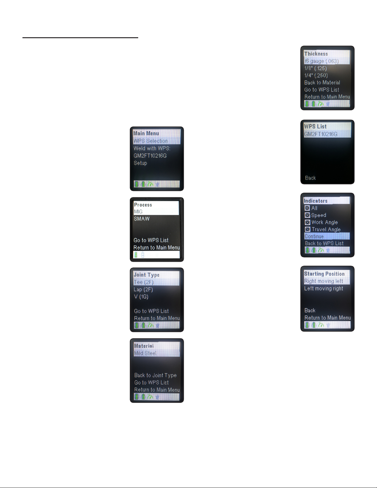
guideWELD® LIVE welding guidance system has 18 default WPS capability to weld for the
tee joint, lap joint, and v-groove joint. The tee joint is in a 2F position, lap joint is in the 2F
position, and the v-groove joint is in the 1G position. All base material is mild steel with
several material thicknesses available in MIG and Stick.
Default MIG WPS
Default Stick WPS
WPS
Number
Material
Thickness
Welding
Position
Joint
Design
Consumable
Type
Electrode
Size
Amp
Range
Welding
Work Angle
Welding
Travel Angle
Welding
Travel Speed
(inch) (AWS Wire Class) (inch) (amps) (Range of Degree) (Range of Degrees) (ipm)
TARGET TARGET TARGET TARGET
SM2FT1351/8 1/8 2F Tee E7018 1/8 120 45 20 11
SM2FL1351/8 1/8 2F Lap E7018 1/8 120 45 20 11
SM1GG1351/8 1/8 1G V-Groove E7018 1/8 120 90 20 11
SM2FT1401/4 1/4 2F Tee E6013 1/8 95 45 20 7
SM2FL1401/4 1/4 2F Lap E6013 1/8 95 45 20 7
SM1GG1401/4 1/4 1G V-Groove E6013 1/8 95 90 20 7
SM2FT1303/8 3/8 2F Tee E6010 1/8 90 45 20 6
SM2FL1303/8 3/8 2F Lap E6010 1/8 90 45 20 6
SM1GG1303/8 3/8 1G V-Groove E6010 1/8 90 90 20 6
Base Material (type): All StickWPS’s are tested with STEEL
Welding Polarity: DC
Mode of Wire Transfer: All WPS’s for SMAW process
Measurement Units: All WPS’s are available in Metric and Imperial.
NOTE: Customizable WPS available
WPS
Number
Material
Thickness
Welding
Position
Joint
Design
Specied
Weld Size
Volt
Range
Wire Feed
Speed
Welding
Work Angle
Welding
Travel Angle
Welding
Travel Speed
(T1, T2) (AWS A2.4) (volts) (WFS) (Range of Degree) (Range of Degrees) (Minimum ipm)
TARGET TARGET TARGET TARGET TARGET
GM2FT10216G 16-18ga 2F Tee 0.09 17 180 45 10 14.7
GM2FL10216G 16-18ga 2F Lap 0.06 17 180 45 10 16.2
GM1GG8216G 16-18ga 1G V-Groove 0.06 17 145 90 10 13.7
GM2FT1401/8 0.125 2F Tee 0.125 18 270 45 10 13.2
GM2FL1281/8 0.125 2F Lap 0.125 17.5 265 45 5 14.7
GM1GG1271/8 0.125 1G V-Groove 0.125 18 230 90 10 13.2
GM2FT1701/4 0.25 2F Tee 0.25 23 360 45 5 8.5
GM2FL1701/4 0.25 2F Lap 0.25 23 360 45 5 10.0
GM1GG1461/4 0.25 1G V-Groove 0.125 22.5 340 90 10 7.7
Base Material (type): All MIGWPS’s are tested with STEEL
Welding Polarity: DC
Filler Metal Size (diam.): AllWPS’s are tested with 0.035
Mode of Wire Transfer: All WPS’s for GMAW process
Filler Metal Type (AWS classication): AllWPS’s are ER70S wire
Measurement Units: All WPS’s are available in Metric and Imperial.
NOTE: Customizable WPS available

8RealCareer® Welding Solutions – guideWELD® LIVE real welding guidance system
Helmet Set-up
View Reference Guide to System Pieces
(page 6) for button positioning and
helmet guides.
1. Turn on the Helmet and Speed Sensor
2. Look at the menu display, use navigation
buttons to determine a choice on each of
the following screens
3. Choose WPS Selection
to start a new WPS or
Choose Weld with WPS,
which is the previous WPS
used. Press the menu
select button to conrm
4. Choose Process.
Press the menu select
button to conrm
5. Choose Joint Type.
Press the menu select
button to conrm
6. Choose Material.
Press the menu select
button to conrm
7. Choose Thickness.
Press the menu select
button to conrm
8. Choose WPS.
Press the menu select
button to conrm*
9. Choose desired indicators
to display. Press the menu
select button to conrm
10.Choose starting position.
Press the menu select
button to conrm
* Only one option may be available based on previous selections.

9RealCareer® Welding Solutions – guideWELD® LIVE real welding guidance system
Calibration Process
NOTICE: The calibration process will need to be
completed before each weld!
The process includes Speed Sensor alignment and Angle Sensor calibration. The process is
the same for Stick or MIG welding except when of using the Stick Calibration Fixture (for Stick
welding only).
Speed Sensor Alignment
Joint/Coupon types
1. Tee (2F)
2. Lap (2F)
3. V-Groove (1G)
Based on chosen joint type, align Speed Sensor to welding coupon
4. Press the red alignment laser button and align laser dots to weld joint
Tee or
Lap Position
V-Groove or
Lap Position
Joint/Coupon Side Views
Tee Joint/Coupon Alignment*
3
1 2
4
calibration continued on next page >
* Laser dots must be within 1/2 inch of
welding joint line (in front or behind)
for optimal speed feedback.

10 RealCareer® Welding Solutions – guideWELD® LIVE real welding guidance system
Calibration Process (continued)
Angle Sensor Calibration
During calibration process and during weld, maintain a rm grasp on welding gun and
Angle Sensor. For best results, keep Angle Sensor in the same location (between palm of
hand/glove and welding gun) without movement.*
1. Tighten the Angle Sensor straps to the palm
of your hand. Cover your hand and the Angle
Sensor with a welding glove
OR
Cover your hand with the welding glove, then
tighten the Angle Sensor straps to the palm of
the glove-covered hand
2. Determine if welding left- or right-handed--use left side calibration xture for left-handed
users, or right side for right-handed users
3. Determine if calibrating for MIG
or Stick process
a. For MIG, insert the welding
gun into the calibration xture
b. For Stick, insert the welding
gun into the Stick
Calibration Fixture
4. Tighten the small screw knob
a. For MIG, tighten so the
welding gun nozzle can just
slide in and out of the xture
with minimal clearance
b. For Stick, tighten on Stick
Calibration Fixture so it cannot
be easily be removed
MIG Calibration Setup Stick Calibration Setup
*Angle Sensor must be on palm side during
welding for accurate guidance feedback.
Angle Sensor calibration continued on next page >

11RealCareer® Welding Solutions – guideWELD® LIVE real welding guidance system
Angle Sensor Calibration (continued)
5. Grasp the welding gun in the desired holding position, pivot handle down and hold
6. Press and release the calibration button on the Speed Sensor, the calibrating screen will
display in the Helmet. Wait for rst part of the calibration to complete before continuing
7. Pivot the welding gun handle up and hold
8. Press and release the calibration button on the Speed Sensor, the calibrating screen will
display in the Helmet. Wait for rst part of the calibration to complete before continuing
9. When calibration has completed, the in-helmet indicators
will display*
10. Remove the welding gun and start the weld without
adjusting the position of the Angle Sensor on
the welding gun
* The Speed Guidance Display will not show until a weld has started. The Speed Sensor needs to detect
an arc before turning on speed guidance.
8
6
9
Work Angle (45)
Speed
Travel Angle (10)

12 RealCareer® Welding Solutions – guideWELD® LIVE real welding guidance system
Welding Icons/Guides
Welding Travel Angle Indicators (right top screen in the Helmet)
Based on the designated WPS, the Helmet will indicate if the travel angle is too far right, too
far left or at the correct travel angle. The travel angle indicators’ (right arrow/left angle) size
will increase when the weld moves farther away from acceptable welding travel angle and
decrease as the weld moves toward the acceptable WPS standards. Correct travel angle
will show up as an equals sign. This will show up when the optimal acceptable WPS
standard is reached.
Welding Work Angle Indicators (left top screen in helmet)
Based on the designated WPS, the Helmet will indicate if the work angle is too high, too low, or
at the correct work angle. The work angle indicators’ (up arrow/down arrow) size will increase
when the weld moves farther away from acceptable welding work angle and decrease as the
weld moves toward the acceptable WPS standards. Correct welding work angle will show up
as an equals sign. This will show up when the optimal acceptable WPS standard is reached.
Welding Speed Indicators (left bottom screen in helmet)
Based on the designated WPS, the Helmet will indicate if the welding speed is going too fast,
too slow, or at the correct welding speed based on the welding guide. The speed indicators’
(plus/minus signs) size will increase when the weld moves farther away from acceptable
welding speed and decrease as the weld moves toward acceptable WPS standards.
Correct welding speed will show up as an equals sign. This will show up when the
optimal acceptable WPS standard is reached.
Rotate Travel Angle Right Correct Rotate Travel Angle Left
Move Work Angle Upward Correct Move Work Angle Downward
Increase Welding Speed Correct Decrease Welding Speed

13RealCareer® Welding Solutions – guideWELD® LIVE real welding guidance system
Main Menu Setup
Under Setup, ve areas are available for additional helmet programming.
Each screen displays a “Back” and “Return to Main Menu” option unless a selection is required.
[Example: Precision Level screen – if no change is needed, simply press the Menu Select Button]
Setup
Speed Sensor Diagnostics Firmware Precision Level Int’l Specs
Bind Turn Logging On/O Versions Set Precision Level:
Select 1, 2, 3 or 4
Metric/Imperial:
Select Metric or Imperial
Test Channels Helmet Update Helmet Language: Select English,
Spanish or Czech
Identify Hand Sensor Update Sensor
Speed Sensor Update Flash Mem
Menu Setup continued on pages 14-20 >

14 RealCareer® Welding Solutions – guideWELD® LIVE real welding guidance system
Speed Sensor (setup)
There are three levels of Speed Sensor: Bind, Test Channels and Identify. Read the
information below for the steps and purpose of each level.
Bind
Each system goes through a binding process when it leaves the factory oor. Binding is
when the Helmet of the guideWELD LIVE system is associated with the Speed Sensor. The
purpose of doing this is to have that Speed Sensor and Helmet communicate data to one
another. The pieces are not connected by cabling; the unit sends radio waves from the Speed
Sensor to the Helmet to tell the user what their speed is during an actual weld. Each Helmet
and Speed Sensor must bind to be able to communicate and send data from Speed Sensor
to Helmet.
All Speed Sensor and Helmets can be re-bound to another Helmet and/or Speed Sensor.
Bind Instructions:
1. Turn on Helmet and Speed Sensor
2. Go to the Main Menu, select Setup and press the menu select button
3. Choose Bind. Press the menu select button
4. Take a pointed object (paper clip point, screw driver tip) and press the bind button for
two seconds
5. View the lower right helmet screen. After binding the screen will display the new Speed
Sensor serial number
NOTE: It is recommended to store the Helmet and Speed Sensor together or
mark them to reduce the need to bind in the future.
NOTE: The bind button is a small recessed button
located on the Speed Sensor next to the power
button. The Speed Sensor “arc o” guidance
lights light up and start to scroll. This may take up
to two minutes for it to correctly bind.
Speed Sensor Setup continued on the next page >
4

15RealCareer® Welding Solutions – guideWELD® LIVE real welding guidance system
Speed Sensor (setup continued)
Test Channels
Each system is set to a specic channel for the radio waves to communicate from the Speed
Sensor to the Helmet. Setting the channel selection is done on the factory oor. The Speed
Sensor and Helmet are not connected by any cabling; the unit sends radio waves from the
Speed Sensor to the Helmet to tell the user what their speed is during an actual weld. There
are 16 available channels. Each system is preset to a specic channel before it leaves the
factory. For best results, dierent channels should be used for each Helmet.
All Speed Sensors and Helmets can be changed to a dierent channel, if needed, for optimal
performance and communication.
Channel Selection Instructions:
1. Turn on Helmet and Speed Sensor
2. Go to the Main Menu, select Setup and press menu select button
3. Choose Test Channels. Press the menu select button
4. View the lower right screen. Choose the most optimal channel based on the lower right
screen bar graph; a longer bar and green color represent the best channels to choose from
Identity
Identity is used to conrm that the Helmet is working with the correct speed sensor.
Identity Instructions:
1. Turn on Helmet and Speed Sensor
2. Go to the Main Menu, select Setup Level and press the menu select button
3. Select Identity and press the menu select button. A signal will be sent to the speed board
4. Look for the arc o lights to blink. This indicates the Helmet and Speed Sensor have
identied each other as working together
NOTE: On the left lower screen in the Helmet, there will be a bar graph
of every channel that is available. Each bar will show the color of green,
yellow or red. Green bars indicate the clearest channels. Yellow bars
indicate usable channels but far less clear. Red bars indicate channels
that are not good to use.
NOTE: Depending on the number of systems, no more than four Helmets
should be set to the same channel. This could bog down the communication
channel, causing delays from the speed sensor to the Helmet.

16 RealCareer® Welding Solutions – guideWELD® LIVE real welding guidance system
Diagnostics (setup)
Diagnostics is used for troubleshooting purposes. There are four levels
of diagnostics: Turn Logging On/O, Helmet, Angle Sensor and Speed
Sensor. Read the information below for the purpose of each level. These
processes should only be done in a troubleshooting interaction.
Turn Logging On/O
The SD card creates a log after each weld to show how the product functioned during that
weld. The SD card can hold up to ve logs at one time. Once past ve, the oldest log will be
removed. Logs are used by Realityworks’ Product Support team for troubleshooting.
• If menu says “Turn Logging On” then Logging is currently o
• If menu says “Turn Logging O” then Logging is currently on
• Turning the Logging feature on only aects future welds
Helmet
Diagnostic testing on Helmet tests the screen graphics for display issues.
Select Helmet and the screens will scroll through the test displaying white on black, black on
white, red and yellow indicators for Travel Angle, Work Angle and Speed, white to black, and
multi color.
Angle Sensor
Diagnostic testing on Angle Sensor tests the connection to the Helmet.
1. Connect the Angle Sensor to the Helmet
2. Turn on the Helmet
3. Go to the Main Menu, select Setup. Press the menu select button
4. Choose Diagnostics. Press the menu select button
5. Choose Hand Sensor. Press the menu select button
The screen will display either “Hand Sensor PASS”or “Hand Sensor FAIL”
Speed Sensor
Diagnostic testing on Speed Sensor tests speed tracking feature capabilities.
1. Turn on Helmet and Speed Sensor
2. Go to Main Menu, select Setup. Press the menu select button
3. Choose Diagnostics. Press the menu select button
4. Choose Speed Sensor. Press the menu select button
5. Shine an incandescent ashlight (LED will not work) up close to each red light on the
Speed Sensor board. Move ashlight from right to left
All 24 red LEDs should light up as the ashlight passes

17RealCareer® Welding Solutions – guideWELD® LIVE real welding guidance system
Firmware (setup)
Firmware is used for software updates of the Helmet and Speed Sensor.
There are four levels of Firmware: Versions, Update Helmet, Update
Sensor and Update Flash Memory. Read the information below for the
steps and purpose of each level.
Versions
Versions show the system software code and is used for troubleshooting for
the Helmet, SPI, Sensor and SDC.
Helmet (Helmet)
SPI (Speed Sensor)
Sensor (Angle Sensor)
SDC (SD Card)
Update Helmet
Update Helmet is used to update the software code.
Update Helmet Instructions:
1. Turn on the Helmet
2. Insert SD Card into the Helmet
3. Go to the Main Menu. Select Setup and press the menu select button
4. Select Firmware. Press the menu select button
5. Select Update Helmet. Press the menu select button
6. Turn o the Helmet to restart
NOTE: Updates will begin and run until complete – do not shut o Helmet during this time.
When update is complete, the screen will ash white
Firmware Setup continued on the next page >

18 RealCareer® Welding Solutions – guideWELD® LIVE real welding guidance system
Firmware (setup continued)
Update Sensor
Update Sensor is used to update the software code on the Speed Sensor.
Update Sensor Instructions:
1. Turn on the Helmet
2. Insert SD Card into the Helmet
3. Go to the Main Menu, select Setup and press the menu select button
4. Select Firmware and press the menu select button
5. Select Update Sensor and press the menu select button
6. Turn o helmet to restart
Update Flash Memory
Flash Memory is the text and graphics on each of the Helmet screens. Update Flash Memory
is used to update the software code.
Update Flash Memory Instructions:
1. Turn on Helmet
2. Insert SD Card into Helmet
3. Go to the Main Menu, select Setup and press the menu select button
4. Select Firmware and press the menu select button
5. Select Update Flash Memory and press the menu select button
6. Turn o the Helmet to restart
NOTE: Updates will begin and run until complete – do not shut o the Helmet during this
time. When update is complete, screen will state“Update Complete”
NOTE: Updates will begin and run until complete – do not shut o Helmet during this time.
When updated, screen will state “Update Complete”

19RealCareer® Welding Solutions – guideWELD® LIVE real welding guidance system
Precision Levels (setup)
Precision Level is the tolerance that is allowed for Work Angle, Travel Angle and Speed to be
in comparison with the WPS. For example, if Work Angle is 45 degrees, precision level would
allow a 45-degree mark miss by 2-3 degrees (42 degrees on the low end, 48 degrees on the
high end) and still be acceptable for the guidance system.
The Precision Levels mode is the area where a user can increase or decrease the precision
of the WPS parameters for the guidance system within the Helmet. All systems are preset at
level 2. See the chart below for exact degrees and speed info.
• Level 1 is a 3-degree up/down variable for Work & Travel Angle
and 1.5-inch increase in Travel Speed
• Level 2 is a 5-degree up/down variable for Work & Travel Angle
and 3-inch increase in Travel Speed
• Level 3 is a 7-degree up/down variable for Work & Travel Angle
and 3-inch increase/decrease in Travel Speed
• Level 4 is a 10-degree up/down variable for Work & Travel Angle
and 4-inch increase/decrease in Travel Speed
Precision Levels continued on the next page >

20 RealCareer® Welding Solutions – guideWELD® LIVE real welding guidance system
Precision Levels (setup continued)
Change Default Precision Levels
To change the default level, follow the steps below and enter the level each time the Helmet
is used. After turning o the Helmet, it will default back to level 2 for Precision Level.
Precision Levels Instructions:
1. Turn on Helmet and Speed Sensor
2. Go to the Main Menu, select Setup and press the menu select button
3. Select Precision Levels. Press the menu select button
4. Select Set Precision Levels. Press the menu select button
5. Select the level [1, 2, 3, 4] to move precision guides. Press the menu select button
6. Go back to Main Menu to begin weld calibration process
International Specications (setup)
Change Measurement Units
To change the default measurement units from Imperial (U.S.) to international specs of
Metric, follow the steps below.
Measurement Units Instructions:
1. Turn on Helmet and Speed Sensor
2. Go to the Main Menu, select Setup and press the menu select button
3. Select International Specications. Press the menu select button
4. Select Metric/Imperial. Press the menu select button
5. Select Metric or Imperial. Press the menu select button
6. Go back to Main Menu to begin weld calibration process
Change Language
To change the default English language to international specs of Czech or Spanish, follow the
steps below.
Measurement Units Instructions:
1. Turn on Helmet and Speed Sensor
2. Go to the Main Menu, select Setup and press menu select button
3. Select International Specications. Press the menu select button
4. Select Language. Press the menu select button
5. Select the desired language. Press the menu select button
6. Go back to Main Menu to begin weld calibration process
Table of contents
Other Reality Works Welding System manuals