Reality Works guideWELD VR User manual

( 1
The guideWELD® VR
welding simulator enables
students to rapidly rene
basic welding skills, learn
proper welding technique
and explore welding
career paths in a safe,
virtual environment.
System Includes:
1. 1 guideWELD VR workstation*
2. guideWELD VR gun attachment (Stick and/or MIG)
3. 3 welding joints (tee, lap, butt joint)
4. 1 set of welding gloves
5. 1 workstation USB cable (not shown)
6. 1 workstation power supply (not shown)
7. Installation guide (not shown)
8. Downloadable guideWELD VR curriculum
Additional Resources:
Software download
9. Installation guide
10. User guide
11. Student guide
12. guideWELD VR curriculum
13. Product Support tutorials and documents
guideWELD® VR
Quick Start Guide
4
1
23
2
*Monitor
not included

2 )
WORKSTATION SETUP
Hardware Setup
1. Plug the USB cord into the guideWELD VR workstation
(Fig. 2A) and into a compatible computer
2. Plug the power cord into the guideWELD VR workstation
(Fig. 2B) and an electrical wall outlet
3. Choose the welding gun (Stick and/or MIG)
4. Line up the connection holes in the workstation with the
connection pins on the connector at the end of the
welding gun hose (Fig. 2C)
NOTE: There is an alignment dot on the welding gun
connector and workstation connector to assist with
proper alignment
Securely fasten the gun hose by twisting the tightening
lock on the gun hose connector (Fig. 2D)
5. Turn the workstation switch from “OFF”(Fig. 2E)
to “ON” (Fig. 2F)
NOTE: The rst time the guideWELD VR workstation
is connected to a computer, these steps must be
completed in this exact order for the computer to
recognize the hardware
2A
2B
2C
2D
2E
2F

( 3
SOFTWARE INSTALLATION AND SETUP
NOTICE! Follow each step below to launch and begin using the
guideWELD VR software. All steps must be completed to begin welding.
Software
Download and install the guideWELD VR software package:
Reference the Installation Guide for additional instructions.
NOTE: Administration credentials may be required
1. Launch the guideWELD VR software by clicking the image on the
computer desktop
2. A Conguration screen will be displayed (Fig. 3A)
3. The following options and selections will
appear on the screen:
• LANGUAGE: Default is English (US)
• RESOLUTION: Defaults to your computer settings
• FULLSCREEN: “OFF”mode is for a windowed
view of the software, “ON” mode is for a fully
expanded screen
• GRAPHICS: Reduce or increase the amount of
graphic usage that the software will need
4. Select to go to the Login Screen
Admin Account
1. Enter the default admin username
and the default password (Fig. 3B)
Username: admin
Password: admin
2. A change PASSWORD SCREEN will appear (Fig. 3C)
3. Create a new password
NOTE: The new password must be 6-14 letters
and/or numbers (example: 123abc)
3A
3B
3C
SOFTWARE INSTALLATION AND SETUP ADMIN ACCOUNT continued on next page >

4 )
SOFTWARE INSTALLATION AND SETUP (continued)
Add an Instructor Account
1. On the Admin Screen, enter Instructor’s rst and last name, click
2. A username is created using the rst two letters of the rst name and up to eight
letters of the last name (example: Tom Washington is towashingt)
Note: The default password is “PASSWORD” and the Instructor will be prompted to
create a new password at rst login
3. Create additional Instructor accounts as needed
4. Click to exit Admin
Instructor Account
Creating Classes
1. Login with Instructor Account information
Note: The instructor will be prompted to create a new password at rst login
2. On the Class Selection screen, click the Add Class button ( ) and type
in the name of the class
Note: the class name cannot be more than 12 characters
3. Click the Save button ( )
Creating Student Accounts
1. Click on the Edit Student icon ( ) to create Student Accounts
2. Enter student rst name and last name – a username will be created
Note: The default password is “PASSWORD” and the student will be prompted to create
a new password at rst login
3. Click Add Student ( ) and create additional Student Accounts as needed
Creating Class Assignments
1. On the Class Selection screen, click on the Edit Class icon ( ) to create a class
assignment list
• Default Class Assignments (pre-assigned Welding Procedure Sheets):
27 MIG and 27 Stick
2. View the Available Assignments on the left side of the screen and click the“+” icon
to move assignments to the Class Assignment list on the right side of the screen
3. The assignment is now assigned (and visible) to the class and Student Accounts
4. Click the “-” icon to remove the assignment from the Class Assignment list

( 5
REVIEW DATA COLLECTION
Class Reports
On the Class Selection screen, click on the Class Report icon ( ) to review
the following:
1. ASSIGNMENT: WPS specication assigned to a class
2. ASSIGNMENT DETAIL: Attributes of the assignment
3. MATERIAL SAVINGS: Monetary savings of utilizing guideWELD VR versus actual
welding materials
4. CLASS AVERAGE: Test grades from each of the students in the class for the
specic assignment
5. TOTAL CLASS AVERAGE: Class average of all tests completed for a specic class
6. TOTAL MATERIAL SAVINGS: Total monetary savings of utilizing guideWELD VR
versus actual welding materials for the class on all assignments
Student Reports
Select a Class to view student reports
1. Click on the Student Report icon to see the result for each student (Fig. 5A)
Note: Class and Student report icons are grayed out until at least one weld
has been executed and saved
2. Click on the Student’s name along the left hand side of the screen
3. View the student’s progress on each assignment
5A

6 )
USER/STUDENT DIRECTIONS
Student Account
Prepare to Weld
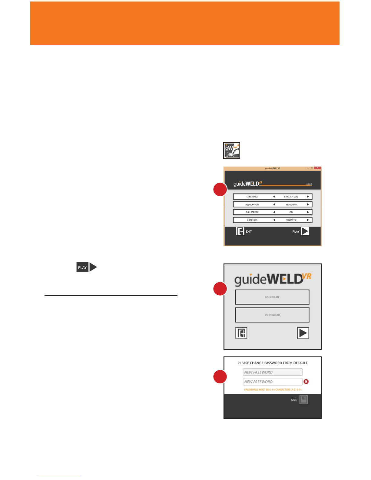
1. Connect the guideWELD VR workstation to a computer with VR software installed
2. Select the welding gun (MIG or Stick)
3. With the workstation powered o, attach the selected welding gun
4. Power on the workstation and launch software and login with Student Account
information. Note: The default password is “PASSWORD”
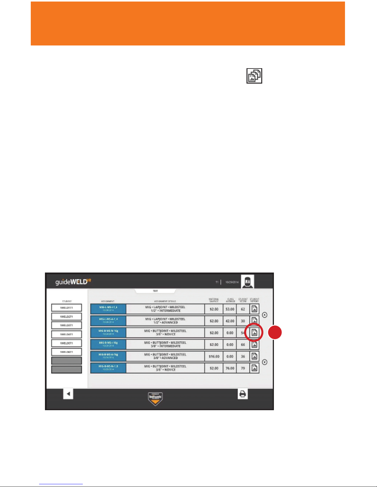
5. Determine the coupon (tee, lap or butt joint) to be used for the assignment and
place chosen coupon on the workstation
6. In the main Student Screen, choose an assignment and click on the Practice button.
Chosen assignment should match welding gun and coupon
Test vs. Practice Mode
Practice mode allows use of the technique guides, while Test mode does not. Test
mode is available only after a student achieves a grade of 50% or higher while in
Practice mode.
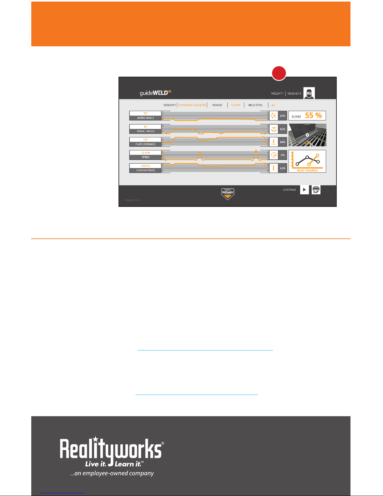
Optional corrective technique guides include:
Note: An equal sign will display when performing proper technique
1. WORK ANGLE: TOP LEFT CORNER – if an up arrow shows, move the butt
of the welding gun up. If a down arrow shows, move the butt of the gun
down. The nozzle or tip of the electrode should remain on path (Fig. 6A)
2. TRAVEL ANGLE: TOP RIGHT CORNER – if a right arrow shows, tilt the
gun to the right. If a left arrow shows, tilt the gun to the left. (Fig. 6B)
3. SPEED: IN FRONT OF WELDING GUN AND COUPON – displays the
travel speed and gives a plus sign when speed should increase and
a minus sign when speed should decrease (Fig. 6C)
4. NOZZLE TO PLATE DISTANCE: ON WELDING NOZZLE/ELECTRODE –
displays correct distance from the work coupon and the gun nozzle.
If positioning is correct, a green circle will appear, while a red arrow
will appear when out of position (Fig. 6D)
5. STRAIGHTNESS: ABOVE AND BELOW THE METAL – the dotted line
shows right location on the work coupon (Fig. 6E)
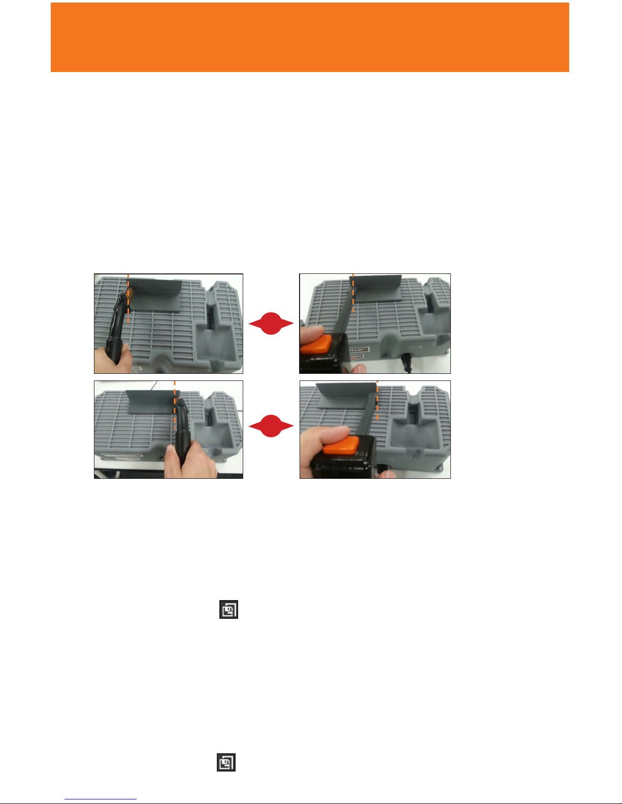
Tacking the Coupon (prior to each weld)
Tacking the coupon needs to be complete on the main welding screen
1. Ensure the message TACK LEFT SIDE OF PLATE AS SHOWN is displayed
2. Bring the physical welding gun into the same position as the virtual welding gun
shown on the screen. The nozzle of the MIG gun or tip of the electrode of the Stick
gun must be centered on the far left edge touching the coupon, with the same
work angle as the virtual welding gun (Fig. 7A)
6A
6B
6C
6D
6E

( 7
NOTE: For a Tee and Lap Joint, position the gun at a 45-degree angle and the gun
handle parallel to the edge of the coupon. For a Butt Joint, position the gun at a
90-degree angle and the gun handle parallel to the edge of the coupon.
3. Pull the trigger (MIG) or press the orange button (Stick) and release
4. Once completed, the TACK RIGHT SIDE OF PLATE AS SHOWN message is
displayed in the simulator
5. Bring the physical welding gun to the right side of the coupon and into the same
position as the virtual welding gun shown on the screen. (Fig. 7B)
6. Pull the trigger (MIG) or press the orange button (Stick) and release
7. Begin weld
Tacking coupon with a MIG gun Tacking coupon with a STICK gun
Execute a Weld
MIG welding
1. Position the welding gun near the coupon as directed by the assignment
2. Pull the trigger to begin welding
3. Move the welding gun in the assigned direction of travel
4. Release the trigger at the end of the coupon
5. Click the Save button ( ) in the lower right corner
Stick welding
1. Allow the electrode to extend until it stops
2. Position the tip of the electrode just outside the coupon starting point as directed
by the assignment
3. Move in the assigned direction of travel to begin welding
Note: If done incorrectly you may stick the electrode to the coupon within the
simulation and will be prompted to restart/unstick
4. To end the weld, back the electrode away from the coupon
5. Click the Save button ( )
USER DIRECTIONS continued on next page >
7A
7B

8 )
www.realityworks.com | 800.830.1416
© 2018 Realityworks, Inc. All rights reserved.
1033040-11 | 7/2018
USER DIRECTIONS (continued)
Reviewing Assignment Results
A results screen is
displayed after
saving the
completed weld
(Fig. 8A)
• If the performance
(indicated by the
orange line) is
inside the gray
shaded area,
the weld was
done correctly.
• If the performance
(indicated by the
orange line) is
outside the gray shaded area, more practice is needed.
Additional Help and Information
1. Complete user guide
2. guideWELD® VR curriculum
3. Product Support tutorials and documents
Online Product Support
We’re here to help! Our online Product Support features video tutorials, downloadable
documents, frequently asked questions and product notices, all of which make it easy
for you to get support for products, software and more, day or night. Find our online
product support area here: www.realityworks.com/support/
Online Store
Supplies, accessories, select simulators, curriculum and more are
available for purchase from our online store 24 hours a day!
Find our online store here: http://store.realityworks.com
8A
Table of contents
Other Reality Works Welding System manuals
Popular Welding System manuals by other brands

CEMONT
CEMONT SMARTY TX 150 Safety instruction for use and maintenance

WeldKing
WeldKing COOLARC 160 owner's manual

Abicor Binzel
Abicor Binzel SR/ABITIGL ABITIG GRIP operating instructions

bester
bester 155-ND Operator's manual

Thermal Dynamics
Thermal Dynamics A80 CUTMASTER operating manual

Leister
Leister Uniroof E operating instructions