3
Revised 11 2023 Drawing No. LP0908
and earth ground must be used. Also, plugging in a USB cable may
connect signal common and earth ground.1
1USB’s shield may be connected to earth ground at the host.
USB’s shield in turn may also be connected to signal common.
POWER SUPPLY REQUIREMENTS
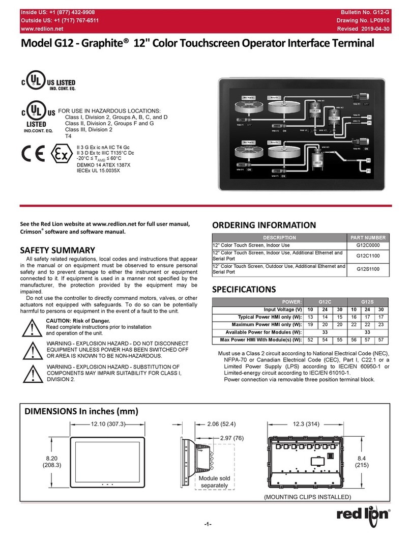
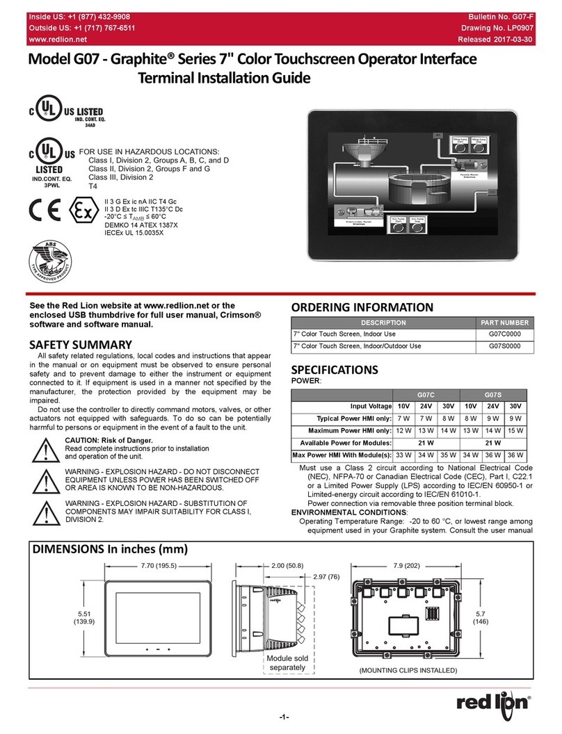
The G09 requires a 10-30 VDC power supply. Your unit may draw
considerably less than the maximum rated power depending upon
the features being used. As additional features are used, your unit
will draw increasing amounts of power. Items that could cause
increasesincurrentaremodules,additionalon-boardcommunications,
SD card, and other features programmed through Crimson.
To ensure you do not exceed the capacity of your Graphite host
power supply, calculate the total power consumption required for
all of your planned modules. Each module’s maximum power
consumption is listed in the Specifications of their Product
Bulletin. The total power available for modules is listed in the
specifications of the Graphite host.
In any case, it is very important that the power supply is
mounted correctly if the unit is to operate reliably. Please take
care to observe the following points:
– The power supply must be mounted close to the unit, with
usually not more than 6 feet (1.8 m) of cable between the
supply and the operator interface. Ideally, the shortest
length possible should be used.
– The wire used to connect the operator interface’s power
supply should be at least 22-gage wire suitably rated for the
temperatures of the environment to which it is being
installed. If a longer cable run is used, a heavier gage wire
should be used. The routing of the cable should be kept
away from large contactors, inverters, and other devices
which may generate significant electrical noise.
– A power supply with an NEC Class 2 or Limited Power Source
(LPS) and SELV rating is to be used. This type of power supply
provides isolation to accessible circuits from hazardous
voltage levels generated by a mains power supply due to
single faults. SELV is an acronym for “safety extra-low voltage.”
Safety extra-low voltage circuits shall exhibit voltages safe to
touch both under normal operating conditions and after a
single fault, such as a breakdown of a layer of basic insulation
or after the failure of a single component has occurred. A
suitable disconnect device shall be provided by the end user.
I/O MODULE INSTALLATION
The physical order of all installed
modules must match the
modules order in Crimson.
Torque screws to 6.0
pound-force inch [96
ounce-force inch] (0.68 N
m).
COMMUNICATING WITH THE G09
CONFIGURING A G09
The G09 is configured using Crimson®software. Crimson is
available as a no charge download from Red Lion’s website.
Crimson updates for new features and drivers are posted on the
website as they become available. By configuring the G09 using
the latest version of Crimson, you are assured that your unit has
the most up to date feature set. Crimson software can configure
the G09 through the RS232 PGM port, USB port, or SD card.
The USB port is connected using a standard USB cable with a
Type B connector. The driver needed to use the USB port will be
installed with Crimson.
The RS232 PGM port uses a programming cable made by Red
Lion to connect to the DB9 COM port of your computer. If you
choose to make your own cable, use the “G09 Port Pin Out
Diagram” for wiring information.
The SD card can be used to program a G09 by placing a
configuration file and firmware on the SD card. The card is then
inserted into the target G09 and powered. Refer to the Crimson
literature for more information on the proper names and locations
of the files.
USB, DATA TRANSFERS FROM THE SD CARD
In order to transfer data from the SD card via the USB port, a
driver must be installed on your computer. This driver is installed
with Crimson and is located in the folder C:\Program Files\Red
Lion Controls\Crimson 3.0\Device\ after Crimson is installed.
This may have already been accomplished if your G09 was
configured using the USB port.
Once the driver is installed, connect the G09 to your PC with a
USB cable, and follow “Mounting the SD” instructions in the
Crimson 3 user manual.
INSERTION/REMOVAL OF THE SD CARD
Insert the SD card into the slot provided with the card oriented
as shown. The card is inserted properly when the end of the card
is flush with the Graphite case. To remove the SD card, push in
slightly on the card.
WARNING: Disconnect all power to the unit before
installing or removing modules.
WARNING - Do not connect or disconnect cables while
power is applied unless area is known to be non-
hazardous. USB port is for system setup and diagnostics
and is not intended for permanent connection.

