Redback A 4506 User manual

Operating Manual
A 4506 6A Battery Charger
A 4512 12A Battery Charger
The A 4506 and A 4512 battery chargers are ideally suited for PA systems requiring battery back up in the event of mains
power failure.
The design incorporates a highly efcient, intelligent, multi stage switchmode battery charger ensuring optimum battery
charging and performance.
This charger has been specically designed for use on sealed lead acid batteries (SLA).
1.0 Features
• Short circuit protection
• Electronic reverse polarity protection
• 2 stage charging
• 2 switched 50 amp outputs
• Automatic boost and oat voltages
• Precision control of boost and oat voltage settings
• Battery Isolator/circuit breaker
• 24V DC Auxiliary outputs (maximum load 1 amp)
• Digital battery voltage display
• Digital battery current display
• Charging mode status indicators
• Mains/battery/low battery status indicators
• 24V out status indicator
• Low voltage cut off to protect battery
• 2U 19” rack mount chassis
• 2 year warranty
• Ideal for sealed lead acid batteries
• Australian designed and manufactured
• Made in Australia
User manual revision number 1.0 26/02/2016

Redback® Proudly Made In Australia
2
Fig 1
2.0 Front Panel Connections
1 Battery Current Indicator
This LCD displays the battery current. A positive gure indicates the battery charging current. A negative gure
shows the current drain from the batteries when the load(s) is being powered by the batteries.
2 Battery Voltage Indicator
This LCD displays the battery voltage.
3 Charging Mode Indicators
The charger has 3 stages of charge and a fault condition.
Boost charge mode - Solid orange LED
Absorb charge mode - Flashing orange LED
Trickle charge mode - Solid green LED
Fault Mode - Solid red LED
4 Auxiliary 24V Out Indicator
This LED indicates when 24V is present at the auxiliary outputs.
5 Power Status Indicators
These indicate what power source the battery charger is powering from.
Mains power - Green LED
Battery power - Orange LED
Low Battery - Red LED
6 Power Switch
Used to turn the unit On or OFF.
A 4506
SLA Battery Charger
Battery Voltage Power
Aux 24V Out
Present
24V DC 6A
Charging Mode
Low Battery
Power Status
Battery
Mains
Battery Current
Boost
Absorb
Trickle
Fault
61 2 4 5
3

Redback® Proudly Made In Australia 3
3.0 Rear Panel Connections
Fig 2
1 240V AC Input
Power is supplied via a 230V mains lead.
2 24V Auxiliary Outputs
These provide 24V DC at a maximum of 1 amp combined output current.
3 Low Battery and Mains Fail Contacts
Normally open contacts which close when a low battery condition occurs or when mains is no longer powering
the charger.
4 Battery Voltage Connection
This lead must be connected to the batteries via a separate cable to that which is connected to the battery +ve
and battery -ve binding posts. This separate lead accurately measures the voltage present at the batteries.
5 Battery -ve Connection
This is connected to the negative terminal of the battery.
6 Load -ve Connections
These binding posts are for the negative connection of the load(s). A maximum load of 50 amps per set of load
terminals.
7 Load +ve Connections
These binding posts are for the positive connection of the load(s). A maximum load of 50 amps per set of load
terminals.
8 Battery Isolate/Reset
This breaker can be used as an isolator to quickly disengage the batteries without having to disconnect leads. It
also acts as a safe guard against short circuits in the battery leads or reverse polarity connection.
9 Battery +ve Connection
This is connected to the positive terminal of the battery.
Model
A 4506
A4512
AC Fuse (M205)
5A
5A
RISK OF ELECTRIC SHOCK
OPEN BY QUALIFIED
PERSONNEL ONLY
!
CAUTION
Manufactured in Australia
By Altronic Distributors Pty. Ltd.
www.altronics.com.au
LOAD 2 (-VE)
LOAD 1 (+VE)
(max load current 50A)
LOAD 2 (+VE)
(max load current 50A)
BATTERY (-VE)
BATTERY (+VE)
240V AC
LOAD 1 (-VE)
Please Note:
Unit suitable for use with Sealed Lead Acid (SLA)
batteries only.
NOTE: Only use batteries of the same make and capacity.
24V SYSTEM ONLY
Battery
Isolate/reset
Separate cable to run to battery
for accurate voltage indication.
THIS MUST BE
CONNECTED FOR
CORRECT OPERATION
Battery
Voltage
+ –
24V Auxilliary
Outputs
(Total maximum
Load = 1 Amp)
Out
1
Out
2
- +- +
Mains
Fail
Low
Batt.
Contacts close
on Alarm
Conditions
7
1 2
5 6
3
WATERPROOF
100A
4 8 9

Redback® Proudly Made In Australia
4
Calculating battery size for PA systems
Total amplifier power in watts
Battery Size = x 1.5 =
Volts
500
=x 1.5 = 31.25AH
24
Required
amps for
1 hour
Therefore a 40AH battery would be suitable Please note: This calculation
assumes 100% duty cycle at full power output into full rated load.
500W amplifier
Battery Size
Connecting batteries in series
+
12V Battery
+
12V Battery
To Charger + To Charger -
2 x 12V batteries = 24V total battery voltage.
+
6V Battery
+
6V Battery
To Charger + To Charger -
4 x 6V batteries = 24V total battery voltage.
++
6V Battery
6V Battery
It is common practice to connect 6V or 12V batteries in series to
create a 24V battery source.
Equalising batteries
Connect in parallel overnight (10-12 hours
minimum) prior to connecting them to the
charger. Failure to do this can cause a severe
inbalance in the charging of the batteries causing
permanent damage.
+
12V Battery
12V batteries connected
in parallell.
+
12V Battery
6V batteries connected
in parallell.
+
6V Battery
+
6V Battery
+
6V Battery
+
6V Battery
5.0 Battery Characteristics
Before connecting batteries to the charger it is recommended that the batteries be equalised as shown in Fig 4.
Batteries should also be connected in series to create a 24V battery source as shown in Fig 5.
** PLEASE NOTE: The A 4506 and A 4512 are 24V battery charging systems. **
Fig 3
Fig 5
4.0 Calculating Battery Size
Before wiring any batteries to the charger it is important to calculate the battery size required for the PA system you are
installing. Figure 3 demonstrates the formula to calculate the required battery size.
Fig 4

Redback® Proudly Made In Australia 5
6.0 Battery and Load Conguration
Ensure that the power to the unit is off both at the mains and the switch at the front. Proceed to wire up the unit
according to the instructions below in gure 6.
Connect your battery to the binding posts on the back of the unit labelled (Battery +ve and Battery –ve) using heavy gauge
cable.
Another lead needs to be connected to the battery from the terminal labelled “Battery Voltage”. This lead needs only
be made of medium duty wire. This lead MUST BE CONNECTED for the charger to operate and is used to measure the
voltage at the batteries.
Connect your load(s) to the binding posts labelled (Load 1 +ve and load 1 -ve and if required to load 2 +ve and load 2-ve).
Note: the load current is limited to 50 amps maximum per load.
Model
A 4506
A4512
AC Fuse (M205)
5A
5A
RISK OF ELECTRIC SHOCK
OPEN BY QUALIFIED
PERSONNEL ONLY
!
CAUTION
Manufactured in Australia
By Altronic Distributors Pty. Ltd.
www.altronics.com.au
LOAD 2 (-VE)
LOAD 1 (+VE)
(max load current 50A)
LOAD 2 (+VE)
(max load current 50A)
BATTERY (-VE)
BATTERY (+VE)
240V AC
LOAD 1 (-VE)
Please Note:
Unit suitable for use with Sealed Lead Acid (SLA)
batteries only.
NOTE: Only use batteries of the same make and capacity.
24V SYSTEM ONLY
Battery
Isolate/reset
Separate cable to run to battery
for accurate voltage indication.
THIS MUST BE
CONNECTED FOR
CORRECT OPERATION
Battery
Voltage
+ –
24V Auxilliary
Outputs
(Total maximum
Load = 1 Amp)
Out
1
Out
2
- +- +
Mains
Fail
Low
Batt.
Contacts close
on Alarm
Conditions
WATERPROOF
100A
+
-
24V BATTERY
BANK
LOAD 2
+
-
LOAD 1
+
-
Fig 6

Redback® Proudly Made In Australia
6
Charging time is dependent on the ampere hour rating of
the battery and its condition of charge.
Typical charge times for fully dis-
charged batteries using 6A model
No. A 4506
24AH 6Hrs
40AH 10Hrs
Typical charge times for fully dis-
charged batteries using 12A model
No. A 4512
60AH 8Hrs
80AH 10Hrs
100AH 12Hrs
120AH 14Hrs
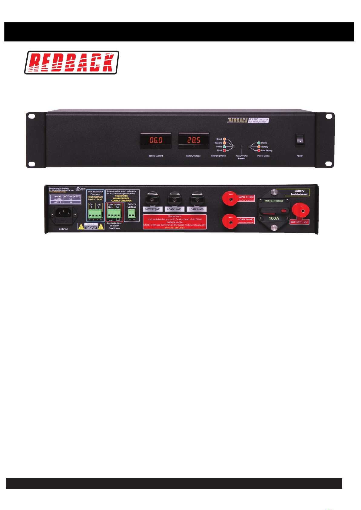
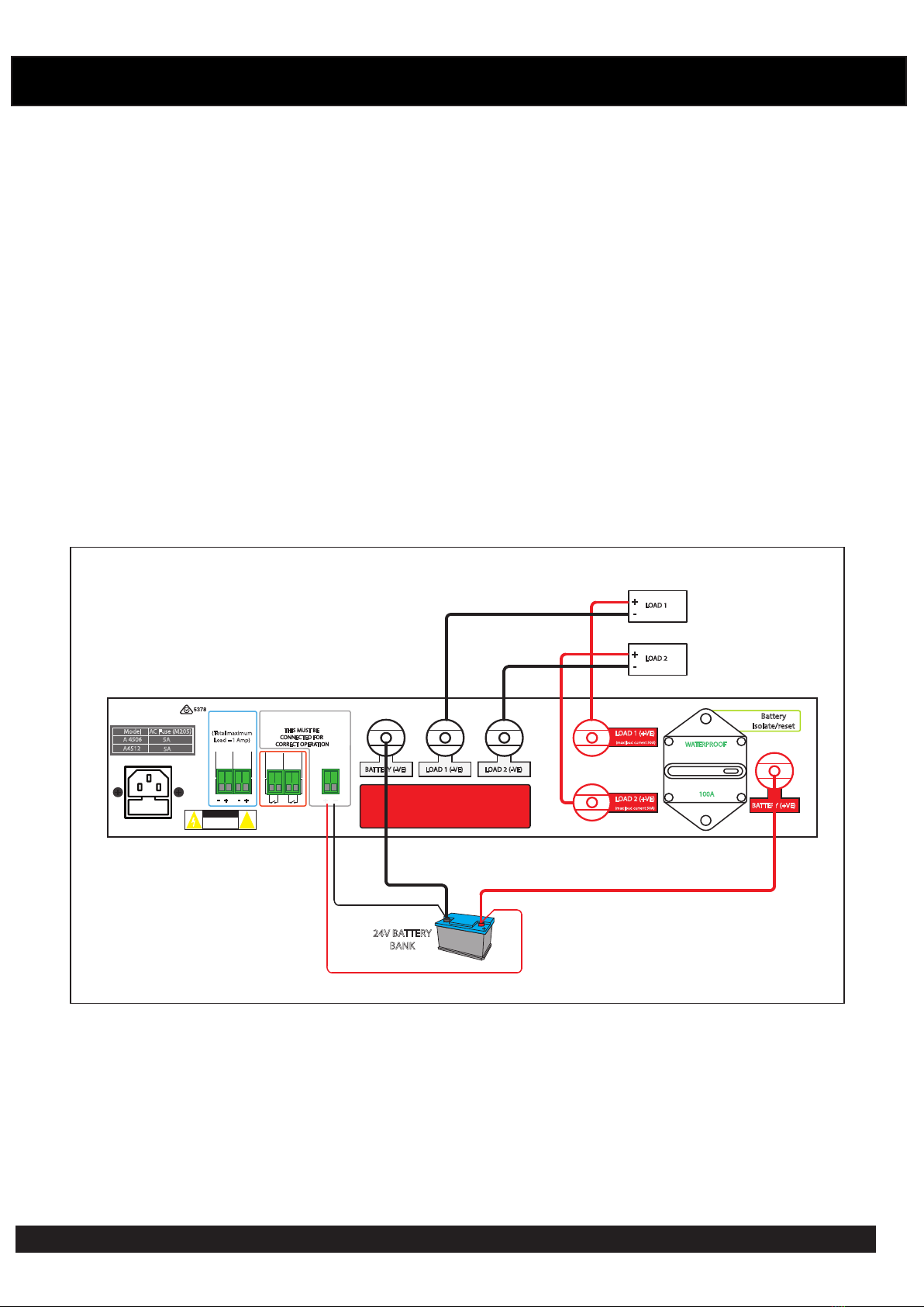
7.0 Charger Operation
Once wiring is nished switch on the unit.
You should see the battery voltage and current draw indicated on the displays on the front panel. This refers to the voltage
available at the battery terminals and the current owing through the batteries. (A positive current gure indicates the
batteries are being charged while a negative current gure indicates that the batteries are supplying power to the load(s)).
It is common for the battery voltage to read nominally higher than the voltage rating of 24VDC.
Whilst the battery is connected to the unit and mains power is applied, the charger will continue to charge the battery.
The charger will charge the battery at “Boost” current (6A for A 4506 or 12A for A 4512) until 29.4V is reached, at
which time the battery charger will continue to “Absorb” charge and then “Trickle” charge the battery in order to keep it
topped up at 27.6V.
LED’s on the front panel indicate when these changes in the cycle occur.
Should mains power fail, the unit will automatically switch the connected load(s) to the battery. When mains power is
restored the load(s) will be disconnected from the battery. LED’s on the front panel indicate when the unit is running of the
mains or the battery.
If power is not restored before the battery voltage drops below 22V, the unit will automatically disengage the battery from
the load. This will prevent long term blackouts from damaging the battery.
Should the unit fail to operate in the above manner refer to troubleshooting.
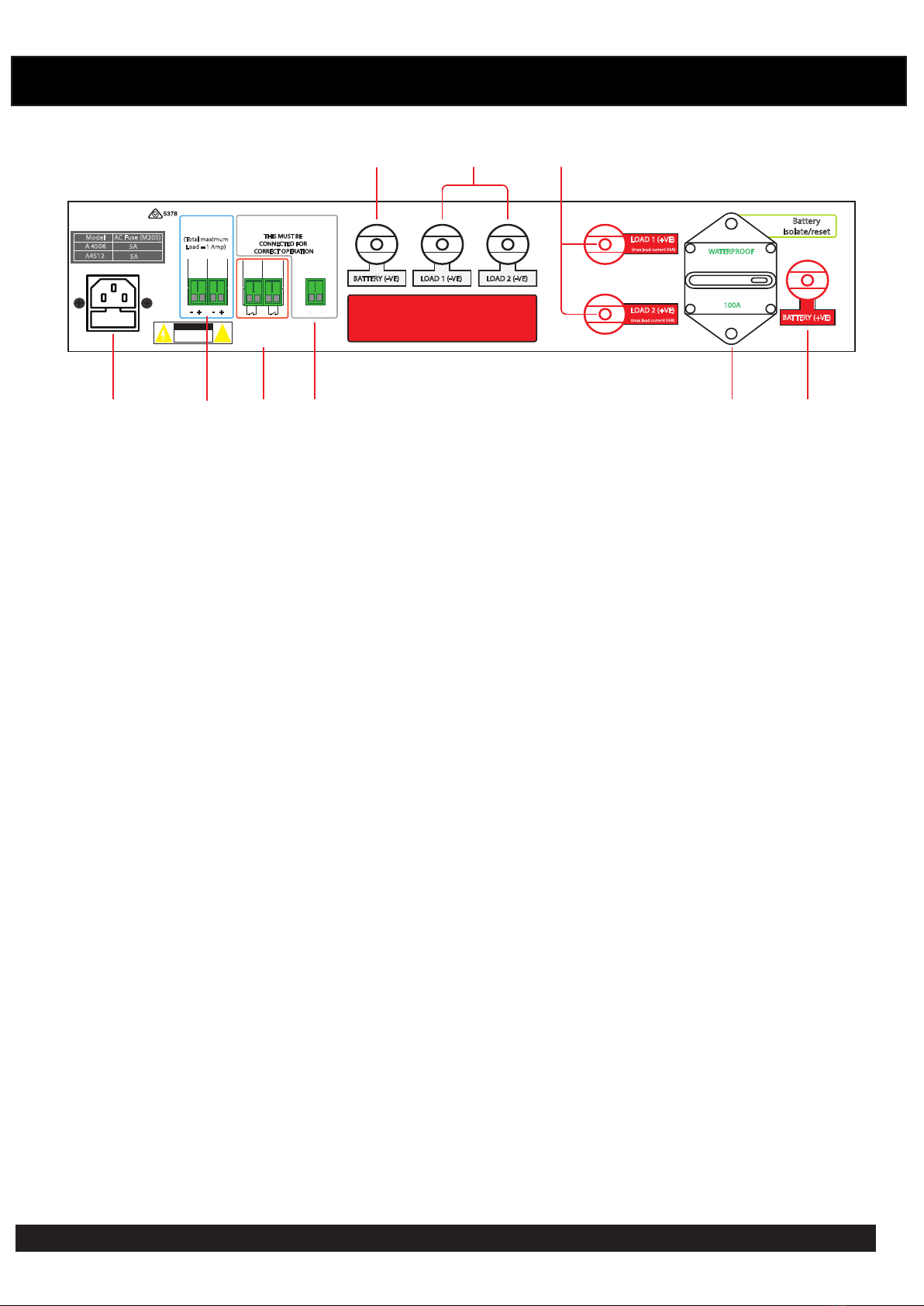
8.0 Battery Isolate/Reset
The A 4506 and A 4512 battery charger models are tted with an 100Amp breaker which is in line with the battery +ve
terminal. This breaker can be used as an isolator to quickly disengage the batteries without having to disconnect leads. It
also acts as a safe guard against short circuits in the battery leads or reverse polarity connection.
9.0 Auxiliary Outputs and Alarm Contacts
24V auxiliary outputs have been provided so that external devices requiring 24V DC can be powered. Two sets of output
terminals have been provided. The total combined load current available from these outputs is 1A maximum and is
protected by an internal 1amp resettable fuse.
Alarm contacts have been provided for external monitoring of the battery charger. These contacts are normally open and
close when there is a mains power fail or a low battery status is achieved.
10.0 Battery Charging Time
The table below indicates typical charging times for the shown ampere hour ratings.

Redback® Proudly Made In Australia 7
11.0 Troubleshooting
Mains led does not come on.
Check that the mains lead is connected.
Check that the AC fuse is installed.
Unit does not display battery voltage.
Check that you have connected a lead from the battery to the terminals labelled Battery Voltage.
Unit will not charge battery.
Check connections to (To battery) terminals and to the battery.
Make sure the Isolate breaker hasn’t been reset.
Load does not power up when mains fails.
Check connections to (To load) terminals and to the load.
Make sure the Isolate breaker hasn’t been reset.

Redback® Proudly Made In Australia
8
12.0 Specications
Input Voltage:.....................................................................240V AC 50Hz
Boost Voltage:............................................................................29.4V DC
Trickle Voltage: ..........................................................................27.6V DC
Boost Current:.......................................................................(A 4506) 6A Max.
(A 4512) 12A Max.
AC Fuse Protection: ..............................................................(A 4506) 5A
(A 4512) 5A
Display:
Battery Voltage.................................................................... 3.5 Digit LCD
Battery Current.................................................................... 3.5 Digit LCD
Trickle charge ..........................................................................Green LED
Float charge ..............................................................Flashing Yellow LED
Boost Charge ..........................................................................Yellow LED
Mains Power: ...........................................................................Green LED
Battery Power: .........................................................................Yellow LED
Low Battery: .................................................................................Red LED
24V DC Auxiliary Out Present.......................................................Blue LED
Controls................................................................................Power On/Off
Rocker Switch
Dimensions:.....................................................˜483W x 330D x 88H mm
Colour: ..............................................................................................Black
Weight:................................................................................. (A 4506) 7.5kg
(A 4512) 9kg
* Specications subject to change without notice.
This manual suits for next models
1
Table of contents
Other Redback Batteries Charger manuals